A Model-Driven and Business Approach to Autonomic Network Management
Mehdi Bezahaf1,*, Stephen Cassidy2, David Hutchison1, Daniel King1, Nicholas Race1 and Charalampos Rotsos1
1Lancaster University, United Kingdom
2British Telecom, London, United Kingdom
E-mail: mehdi.bezahaf@lancaster.ac.uk; steve.cassidy@bt.com; d.hutchison@lancaster.ac.uk; d.king@lancaster.ac.uk; n.race@lancaster.ac.uk; c.rotsos@lancaster.ac.uk
*Corresponding Author
Received 26 January 2021; Accepted 26 March 2021; Publication 03 June 2021
Abstract
As corporate networks continue to expand, the technologies that underpin these enterprises must be capable of meeting the operational goals of the operators that own and manage them. Automation has enabled the impressive scaling of networks from the days of Strowger. The challenge now is not only to keep pace with the continuing huge expansion of capacity but at the same time to manage a huge increase in complexity – driven by the range of customer solutions and technologies.
Recent advances in automation, programmable network interfaces, and model-driven networking will provide the possibility of closed-loop, self-optimizing, and self-healing networks. Collectively these support the goals of a truly automated network, commonly understood as “autonomic networking” even though this is a prospect yet to be achieved.
This paper outlines the progress made towards autonomic networking and the framework and procedures developed during the UK Next Generation Converged Digital Infrastructure (NG-CDI) project. It outlines the operator-driven requirements and capabilities that have been identified, and proposes an autonomic management framework, and summarizes current art and the challenges that remain.
Keywords: Autonomic network management, intent-based networking.
1 Introduction
Autonomic networking promises to radically change the way we deploy and operate future networks [1]. The ultimate aim of autonomic networking is to facilitate self-managing networks, which would be capable of overcoming the increasing complexity of today’s networked systems.
In the UK, an ambitious project called Next Generation Converged Digital Infrastructure (NG-CDI) [2] has been researching the autonomic networking space. The project has split the goals of self-managing (’intelligent’) networks into three technology strands with the properties of being agile in development, autonomic in management, and autonomous in diagnosing and fixing faults. This research is being conducted with multiple UK academic partners and a leading network operator, British Telecom (BT). The academic and commercial joint research ensures that long-term commercial technology goals are seeded in the academic and theoretical discussions, which will guide the development of the project and implementation technologies and techniques. This paper outlines the progress made towards autonomic networking and the framework and procedures developed during the NG-CDI project. It outlines the operator-driven requirements and capabilities; it proposes an autonomic architecture and summarizes current art and the challenges that remain.
2 Future Network Requirements
The management complexity of enterprise networks – including telecommunications – is well known and stems from the rapid growth of infrastructures and the increasing number of offered services [3].
Traditionally, deployment of new services has involved reinvestment in infrastructure, extensive pre-testing, and people-intensive service support in the operation, requiring several hundred people to deliver in an organization such as BT. Future services are also expected to change ever more rapidly – and unpredictably – and therefore organizations need to drastically reduce the time it takes for innovative new services to be launched. This requires improvements in the agility and responsiveness of the network infrastructure to meet evolving customer requirements.
The current static and human-driven approach to controlling the vast numbers of critical devices attached to the existing network infrastructure is unsustainable. Recent research also suggests that continued rapid growth is commercially unviable and usability for future predicted services and applications is at risk [4].
In the 21 Century, automation plays a significant role in the development and operation of complex systems. The concept of “network autonomics” revisits design concepts of biological systems [5, 6], including the human autonomic nervous system. Many processes are of course already automated in operating a network business. But when the system, environment, or business requires modification, these automated processes need to be updated, entailing cost and disruption.
A potential input to the autonomic network is an “intent” [13] interface. Intent-Based Networking (IBN) statements use high-level declarative language to specify outcomes and high-level operational goals. These goals do not determine how they should be satisfied or by which network mechanisms and devices. An Intent-based interface (also known as the “intent plane”) into the autonomic network, would dramatically reduce the human-driven management tasks and complexities and provide input into the autonomic networking system.
An autonomic system augments an automatic operation by incorporating self-learning, which makes the changes themselves automatic. Changes to the system of automation are derived through machine learning, based on measurements of the operation and its KPIs, and optimized for some business goal.
Closing the self-learning loop in this way makes the closer tracking of requirements more economical. But the control system now has a greater influence on the continued successful operation of the process it controls, and so needs to be constructed in specific ways. These incorporate not only the building of the initial control algorithm and machine learning mechanisms but also particular system protection features. The following sections describe the incorporation of these principles into the building and operation of autonomic network systems.
2.1 Summary of Requirements
The range of operational processes that can benefit from autonomic operation includes all those which are sufficiently instrumented to provide the data for machine learning, control levers to regulate the process automatically, and which would naturally evolve to keep pace with changing conditions. These include optimizing the allocation of service requests to network slices; the allocation of network resources to these slices or to optimize traffic flows generally, and a range of service assurance processes. In the latter, the optimum action to take may depend on the criticality of a failed network element to the system as a whole, or to the state of the traffic flows at the time, or to other constraints such as back-up resources available. All these are open to machine learning as they give rise to volumes of network event data, can be controlled through automated means, and require regular re-optimization in the face of dynamic changes in the network state.
To describe the NG-CDI architecture, it is useful to initially identify the key management functions of an autonomic network [10, 12]. The management layer of an autonomic network typically has access to different control and monitoring interfaces to enforce routing and configuration decisions and receive control feedback. At the heart of any autonomic system is the ability to fulfill service delivery requirements under changing conditions. During normal conditions, an autonomic network must be able to fulfill user policy by adapting the configuration of the underlying infrastructure, with minimal user input. This typically requires the execution of several decision processes to define optimal allocation policies (network and compute resources) given the resources of the infrastructure and the service requirements. Decision processes must run both after a policy change, as well as during operation, in order to identify when services require additional resources to meet the required service level (scale up/down) [11].
In parallel, an autonomic network must be able to predict and manage operational anomalies, including failures and attacks, in a timely fashion. During normal operation, an autonomic network must offer failure prediction mechanisms and adapt appropriately the network configuration, to minimize service delivery degradation. Furthermore, an autonomic network must contain mechanisms that can detect network failures, by analyzing monitoring information, and recover and remediate the impact of these failures in service delivery, with minimal human intervention. Finally, the decision processes used to support the processes require continuous training, in order to improve future decision making. Continuous training requires the collection of monitoring information from the system and tuning the parameters of control algorithms to reflect the discovery of new behaviors, statuses, or events.
To implement the capabilities above, it will require the monitoring and analysis of network state, including inputs from:
• Network elements
• Element configurations
• Historical network usage
• Current network usage and state
• Traffic flows
• Users and End-hosts
• Application requirements and performance data
• Application, User and Network Service-Level-Agreements (SLAs)
• Intended network design and operation specifications.
The network input and state above will be available as data sources and relatively raw and unprocessed, some data will be incomplete and certain states may have limited relevance. Therefore, post-processing of the data streams and state will be critical to automatically generate meaningful and useful measurements, so that events may be classified, assessed, and decisions may be taken.
Several additional technical and commercial requirements (listed below) should also be considered for truly autonomic networking. First, an autonomic control system must be able to deal with large complexity and scale and maintain high levels of service delivery while maintaining low operational costs. Second, autonomic networks must support network evolvability and agility by allowing seamless support for new products, trials, and models. Enabling such a level of agility can increase drastically the complexity of control algorithms since they must fulfill the requirements of multiple diverse policies. Third, an autonomic network infrastructure must target service levels on customers, optimized over a range of investment timescales. Fourth, because the delivery of service requires the coordination of multiple administrative domains, an autonomic network must be able to interact with existing and new external control processes, through standardized control and information exchange interfaces. Fifth, the autonomic network infrastructure must target service levels on customers, optimized over a range of investment timescales. This aspect is expanded in the next section. Each of these aspects entails different dimensions of business impact. Employing greater levels of automation in these processes opens the system to risks that are associated with any control system. Autonomic networks must incorporate risk models and methods for mitigation in their decision processes.
3 The Autonomic Network System
Fundamentally, autonomic systems are designed to adapt their behavior in response to change. The automated response to individual events adapts according to the pace of change in the environment. The learning rate is also affected by the statistical properties of the system data. Automated responses can generally be enacted in a few milliseconds, whereas the self-learning loop might typically take weeks or months, depending on the dynamics of the process under control. Beyond this, more fundamental changes would still require human activity, with generally longer timescales. The effects on the business and customers also take place on a range of timescales and other factors – for example, when and how much is invested in infrastructure capacity versus maintenance operations, price impacts, and service levels. These features are described next, in terms of two examples from different domains of network operation.
3.1 Process Clock Speed
The first example is network slicing automation. Instantiating a new network slice can be fully automatic and straightforward. This operation should be an immediate action taking a few milliseconds. Re-allocating an existing network slice can also be quasi-real-time and should take a few minutes. In an autonomic system, these automatic actions are continuously optimized by a slower process, encompassing the collection of data and subsequent processing for statistical learning. This can involve a timescale of weeks. The creation of the initial or new slice template typically involves human activities in requirements definition and design, with a still longer timescale.
The second example emphasizes the timescales of business and customer impact. In Service Assurance, a balance needs to be struck between increasing network capacity to provide a higher level of redundancy for service protection, and proactive maintenance which reduces faults in the first place. These choices rebalance between reactive route protection and proactive maintenance. Each has its consequences on service levels and costs and runs on different process timescales. This currently involves separate manual business processes. Autonomic control of these processes enables them to learn from their performance and to be balanced according to business priorities.
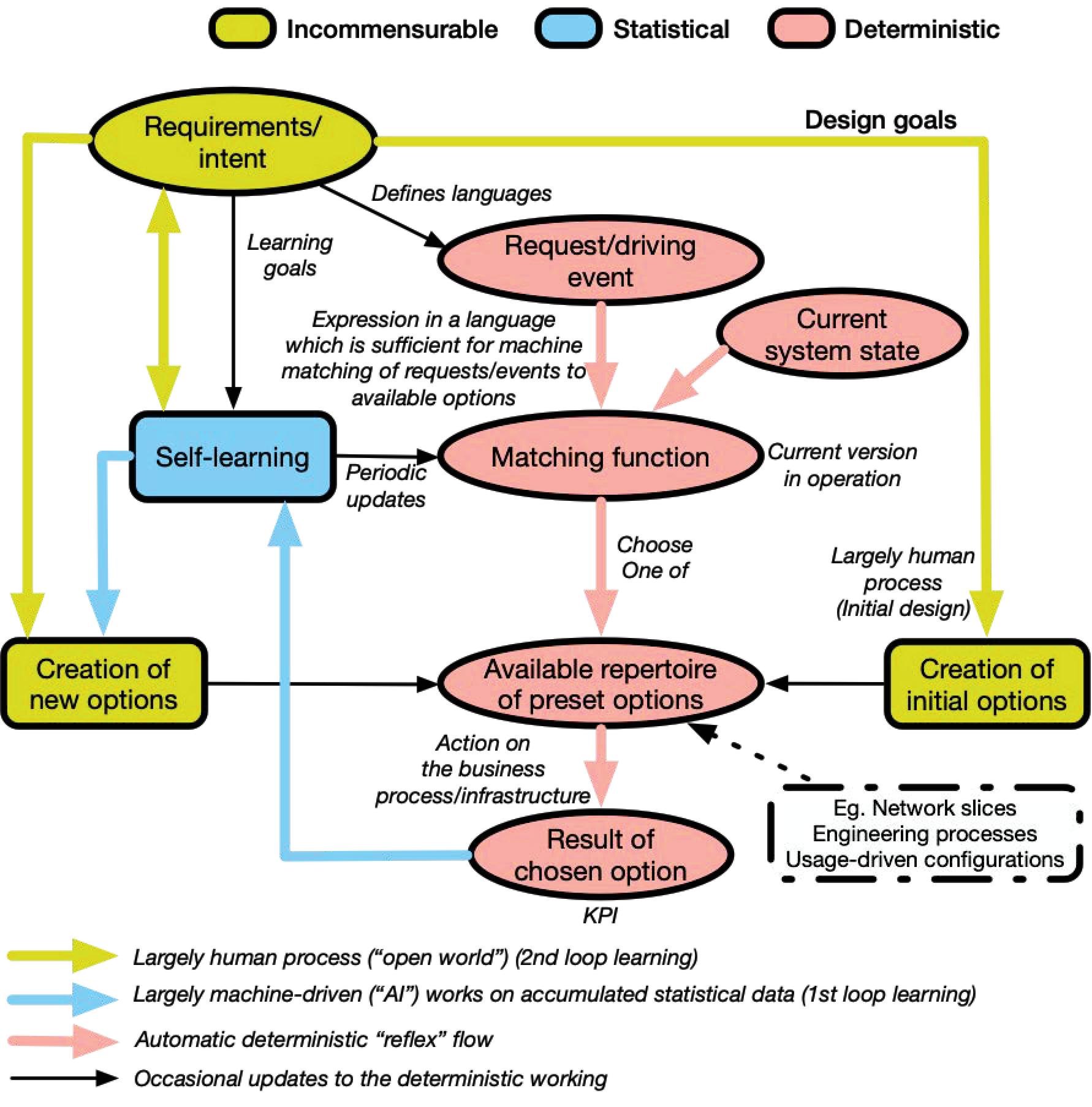
Figure 1 Generic process for autonomics.
3.2 Generic Process for Autonomics
The initial stage in the generic process of autonomics is the development and agreement of new service requirements. It represents the merging and reconciliation of the various stakeholders’ intent – high-level operational goals – which involves human actions in balancing the likely incommensurable requirements of the different stakeholder domains. The output is a formal set of definitions expressed in a way that a machine can interpret, and a repertoire of network or process solutions that fit these requests.
Figure 1 describes the generic process for the operation of autonomic networking – irrespective of the domain of the business process under control. The advantage of a domain-independent architecture is that it reduces cost and risk by establishing a rigorous common autonomic architecture. The yellow arrows and states represent the balancing of incommensurable requirements of the stakeholders, through largely human actions, the light blue represents the statistical machine-driven actions, and the light red represents the deterministic automatic actions. Beforehand, the operator through a human process will first define the language that is going to be used by the system to translate the human-inquired intents using a structured request, via a declarative policy language. This then creates a list of initial options that match these structured requests and translates them to technical low-level imperative policies.
When the system subsequently receives a new request, expressed in the agreed language, the machine can match in a deterministic way the request against its repertoire of available options. The chosen option is then automatically translated to technical low-level policies and deployed. The selected actions and the resulting performance are monitored through agreed KPIs, which enables self-learning to adjust the mapping of requests to the repertoire of actions. It should be noted that this repertoire includes the available span of reconfigurations and service orchestrations available under automatic control. Changes in the requirements, the environment, or the system may mean that the existing repertoire could become insufficient. If, in this case, the required performance cannot be delivered from the initial repertoire of options, new ones can be designed – essentially returning to the initial human process of negotiation between incommensurate needs of the stakeholders and the design and implementation of new pre-set options. Note that the self-learning process is statistical but also gets input from the human about the learning goals.

Figure 2 Building an autonomic system.
3.3 Building an Autonomic System
This section describes the architecture in terms of a rigorous process for building an autonomic system. An autonomic system deployed in a real business environment is a set of continuous, living processes and not a static solution. This is necessary to ensure it can learn and adjust on all relevant timescales, adapt to changes of different natures and scales, and operate safely.
We represent the different constituent processes as separate “stages” for clarity of explanation, although all five stages are in operation continuously in a nested way. These are shown in Figure 2. Describing the stages as quasi-sequential separates the different clock-speeds of each process and helps define the nature of each process. For this reason, we describe the five stages in sequence.
3.3.1 Stage 1: Creation
The first stage encompasses the iteration of a proposed solution between a range of business domain owners and solution analysts. Their requirements are incommensurable and not easy to quantify. Initially, it is not fully clear what is feasible and will only be characterized in the light of the analysis activity involving an interplay between the original requirements. Part of the negotiation is the articulation of the real system limitations found and the projected cost of alleviating these limitations. For example, do we implement the nearest equivalent service using current network functionality, or should we invest in some new capability? The iteration amongst the parties continues until the ambiguity is resolved, and a formal description that outlines the operation of the system in run-time is defined.
The formalized output defines the following measures and variables (judged, via the iterations and analysis, to represent the behavior of the system well enough for the current business purpose):
• Business aim. A set of numbers that represent the balance between cost and service, risk levels, etc. The goal to reach for the system (KPI).
• Input parameters. The measures that characterize the system state and the nature of the real-time request/stimulus.
• System levers. The repertoire of actions made available for choice by the algorithm classifier to control the system.
• Goal measures. The KPI defined for the system’s performance to reach the goal.
• The initial algorithm. The algorithm created as a result of the analysis that sufficiently represents the system.
• System limits. A list of all available resources and capacities.
In terms of processing clock-speed, stage one is a slow clock-speed that typically works at month timescales.
3.3.2 Stage 2: Automatic Operation
Service requests or stimulus for process action is detected by the control system under the formal description agreed. The stage 1 formalized output should be sufficient for the system to take reflex and automatic – completely deterministic – actions, with no human interaction (typically sub-second timescales). The rate of event arrivals means that human intervention would be impossible. Instead, the system performance is assessed statistically over a longer period, in the next stage.
3.3.3 Stage 3: Self-Learning
If the system model defined for Stage 2 is complete (the entire state of the system is determined, and actions follow completely known rules), there is no need to self-learn from changes in the system or environment. This applies for example to famous examples of game-playing computers. The rules and goal are static in these examples. This means that the space of possibilities can be explored with arbitrary thoroughness, with all the conditions held constant – a luxury not afforded to real business systems in real dynamic environments. The learning in the gaming examples takes the form of exploring beforehand the combinatorial space of possible moves. If this is very large, the space is populated and refined during the creation of the algorithm by capturing existing games and generating many more through adversarial techniques. In the architectural stages described here, this would correspond to Stage 1 – the analysis.
In the general case of a real system, the system model (“language”, parameters, algorithm, etc.) is assessed to be sufficient for the purpose in Stage 1. But it is incomplete. The measurements of the system and the repertoire of actions are agreed to be a good enough representation of the system, but there will be characteristics of the system and its environment which are not captured. When these exogenous causes affect the system, the measured parameters will be altered in some way, and the classification algorithm in use would continue to represent the system behavior before the change. To cope with such changes, statistical self-learning is employed as described in Stage 3. If the change is significant enough that the existing scheme of measurements is now considered to be an insufficient model of the system, a different process is needed (Stage 5).
For statistical self-learning, data are gathered on each incoming event, according to the agreed parameters/language (the arriving request or stimulus, the current algorithm, the action taken, the system state, and the success measure (KPI)). Self-learning is then used on the same system data (measured parameters) to create new algorithms that operate in parallel to the one in operation but do not act on the system. Instead, their performance is measured as if they had been in operation. If one of these outperforms the one in operation (subject to consistency, accuracy, and size of impact thresholds (also set in Stage 1), it is substituted as the one in operation.
In general, the choices made by the algorithm are not automatically acted upon. There are possible modifications made to the classifications made by the algorithm for the protection of the real operation, or to implement learning strategies. These are tackled in the next stage.
3.3.4 Stage 4: System Protection
This stage is about protecting the real business process/infrastructure technically and commercially. The real system has limited capacity (e.g., network load, or the number of engineers available for a process). Anomaly detection of the data flows can signal changes that are unexpected in nature or timescale. These will be used to provide useful data/insights on the problem, and trigger processes, such as alerting field or desk engineers to investigate and take remedial action. An accumulation of smaller-scale problems may be used by processes such as scheduled repair.
The stages so far relate to changes within the established paradigm – the language of the chosen parameters. “Established” means that the system under this description has been subject to the analysis, iteration, and interdomain negotiation and agreement of sufficiency in Stage 1. In general, there will be changes that mean that the previously agreed paradigm – language – is no longer sufficient to describe the new circumstance. This is covered in the final stage.
3.3.5 Stage 5: Second loop learning
Stages 2–4 have operated within the formal definitions set up in Stage 1. They are thus operating in a “closed world” environment. Their scope of measurement and action repertoire has been selected and determined by Stage 1. The language is fully defined.
A change in the environment or the system may be of a scale that requires a new language to capture it. These might be, for example, changes to the technology or process, environmental changes that affect the system (e.g., climate change), market changes that introduce new behaviors, or significant changes in the business goal. There may be opportunities for improvement such as the implementation of further system measures that could improve the accuracy of the control model. All these causes outside the system paradigm – “open world” – need a modified language to describe them. The business, therefore, needs to set measures and thresholds that detect possible open world effects on the system. This will trigger Stage 5 – Second Loop Learning – which is identical to Stage 1. This complete refresh of the system will similarly entail a return to negotiating and iterating incommensurable goals and so will be a human process, albeit aided by various triggers set in the process, and extensive data analysis.
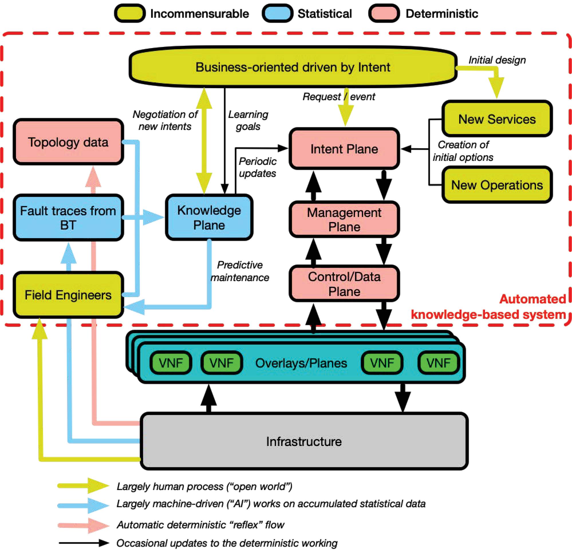
Figure 3 High-level NG-CDI architecture.
4 High-level NG-CDI Architecture
In the context of the NG-CDI project, we apply the concept of autonomic systems presented in the previous section. Figure 3 illustrates a high-level view of a possible NG-CDI architecture. In the Business-oriented driven by Intent plane, the operator defines the initial design of new services and operations. These will help the Intent plane to map the incoming intents, in a deterministic way, to an intermediary intent language, which will have been agreed beforehand.
The system collects data from multiple sources and in different ways. Field engineers interact (human process) directly with the infrastructure; standard activities are captured along with other information.
BT uses a range of statistical algorithms in its operations. Examples range from identifying individual customer faults correlating service characteristics with electrical line characteristics across the whole network, to optimizing the workflows of every individual field engineer based on geography, fault type, skill levels, job times, and several other parameters. Finally, in a deterministic way, the system collects information about the topology.
All this accumulated information (topology data, fault traces from BT, and field engineers) will then feed the knowledge plane that uses statistical algorithms to predict for example any maintenance on the infrastructure to the field engineers, periodically assist the intent plane to improve the intent mapping process and to make better decisions, or help the business plane for possible negotiation of new intents and their definition.
As described in the previous section, the process of stakeholder negotiation towards the expression of intents in machine language is a largely human process, which balances incommensurable requirements involved in creating new services and operations. Please note that this process of negotiation is referred to as the business plane in the rest of the document. The knowledge plane acts as a repository for the different types of captured information as well as the training goals.
In the next section, we present in detail the automated knowledge-based management system and the relationship between different planes. We use “knowledge” in the following section and Figures to mean the collection of information that supports learning, including history, for underpinning autonomic management. The repository can be used by various processes such as risk assessment and to inform actions.
4.1 Automated Knowledge-based Management System
At the outset of the NG-CDI project, it was essential to establish the project research goals, these were structured around five different Research Contributions (RCs):
• RC1 – Agile converged infrastructure systems architecture: The first research contribution is to understand how to build reliable and flexible architectures able to automate operations using the technologies of future networks.
• RC2 – Future network operations and services: RC2 is all about automated processes to capture and predict service characteristics based on use-cases; automated fulfillment of service guarantees and automated service ecosystem.
• RC3 – Autonomic knowledge framework: In order to operate the network in an automated manner, RC3 enables system measurement and data collection.
• RC4 – Autonomous diagnostics and response: The massive volumes of collected data in RC3 will feed into RC4 in order to automatically, and using different machine learning and deep learning techniques, detect disruptions, learn, and provide responses.
• RC5 – Future organizational dynamics: RC5 examines how to bring all these new research challenges together to improve organizational performance through improved service assurance and enhancing organizational capabilities.
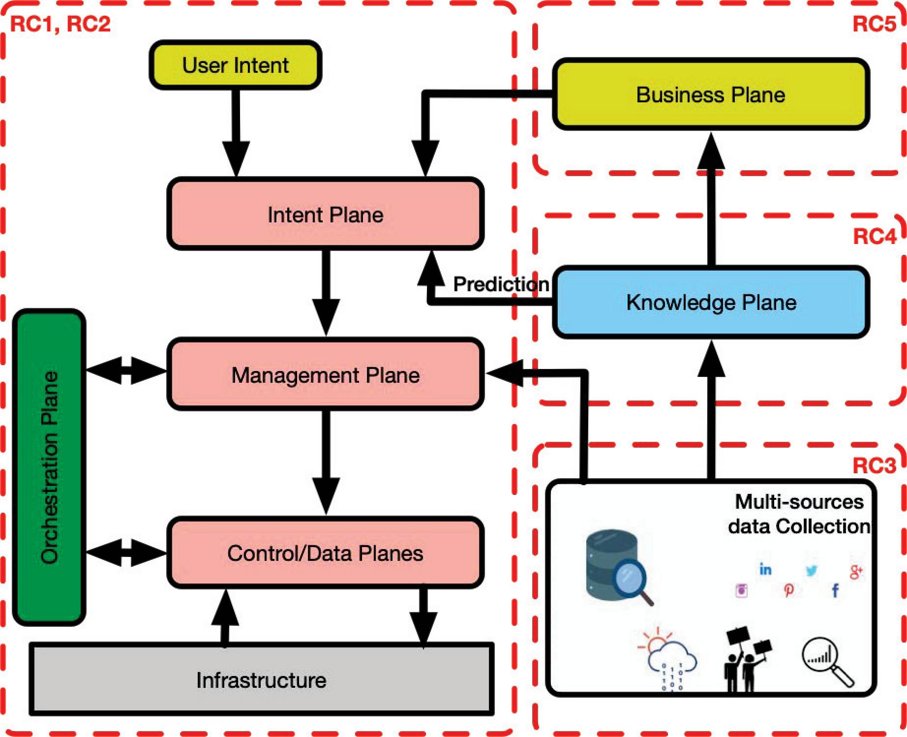
Figure 4 Automated, knowledge-based management.
We have investigated the adoption and extension of the Knowledge Plane proposal by David Clark and others [7] along with autonomic network and service management within the context of the ITU-T Focus Group Technologies for Network 2030 [8].
Figure 4 represents the resulting automated, knowledge-based management architecture with all the research challenges introduced above. RC1 and RC2 cover the intent plane, management plane, control/data planes, and orchestration plane. RC3 concentrates on data collection and classification. RC4 processes all collected data from RC3 in the knowledge plane using different deep learning and machine learning. Finally, RC5 is represented by the business plane. In the following section, each of these planes will be presented.
4.1.1 Intent plane
Improving the level of automation and intelligence has become an intrinsic demand on network management operation and maintenance. With key properties of intelligent and closed-loop intent assurance, Intent-Based Networking (IBN) can be a powerful solution to achieve in the context of predictive maintenance and automation.
An intent designates a requirement that can be expressed from an external client, application, or owned by the network operator (internal). In the first case, the intent is more about quality and is expressed in a high-level manner. For example, “I want connectivity or reserve me an audible connection”. In the case of the network operator, the intent is more about quantity and it is expressed in a more low-level/network-level manner and with more precision than in the previous case. For example, “restrict the load to 50% maximum on each link”.
• Multi-layer Intent system
Once an intent arrives into the system, it has to pass through different stages of processing before reaching the management plane. In fact, the intent needs some translation processes to go from a high-level form to something more technical and feasible at the management plane.
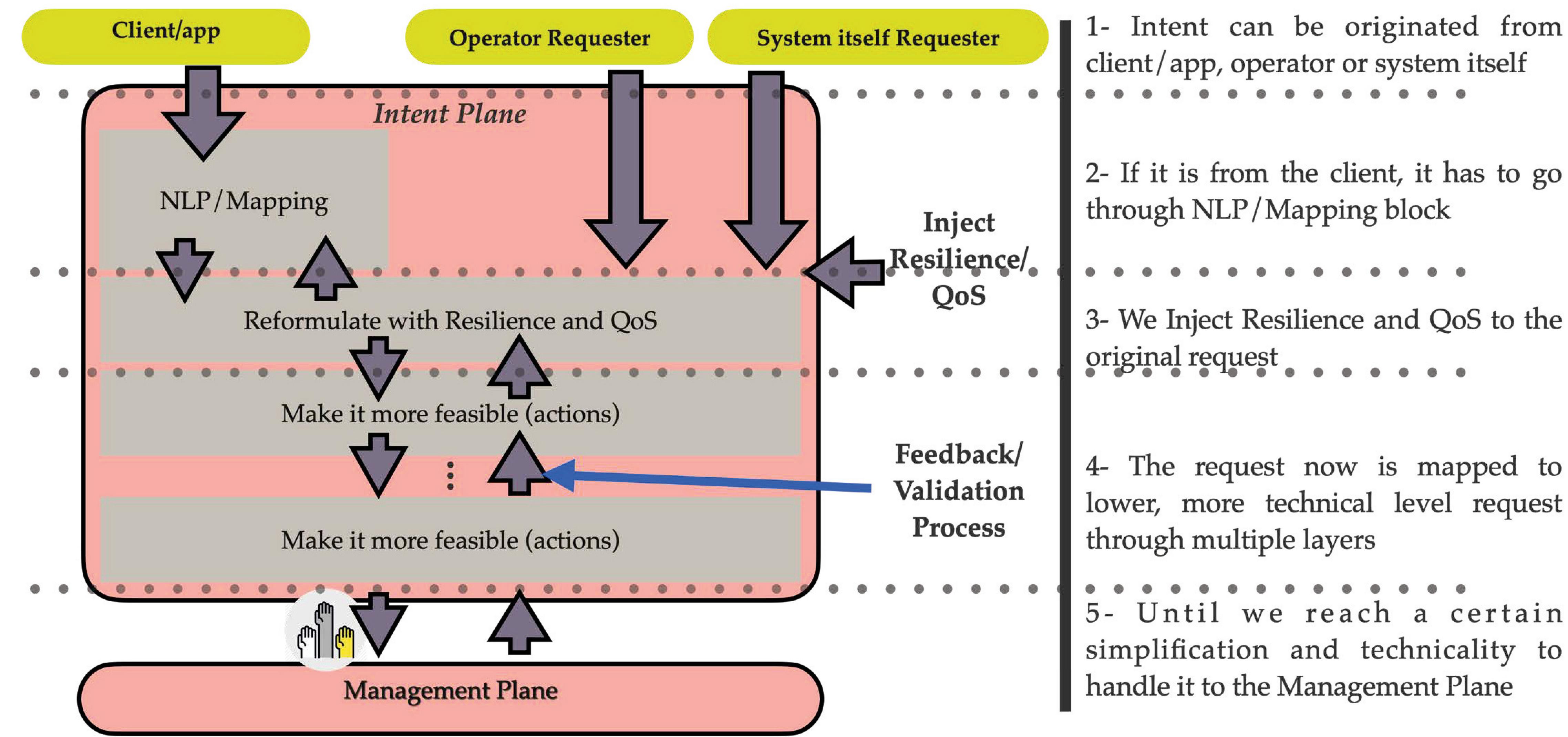
Figure 5 Multi-layer intent system.
Figure 5 shows the multi-layer nature of the intent plane. We believe that an intent originated from a client or an application is more high level than an operator or system itself intent. For this reason, the client’s intent goes through an intent translation process in order to be mapped from a verbal intent to action. The more we go down through the layers, the more the intent becomes technical and feasible for the management plane.
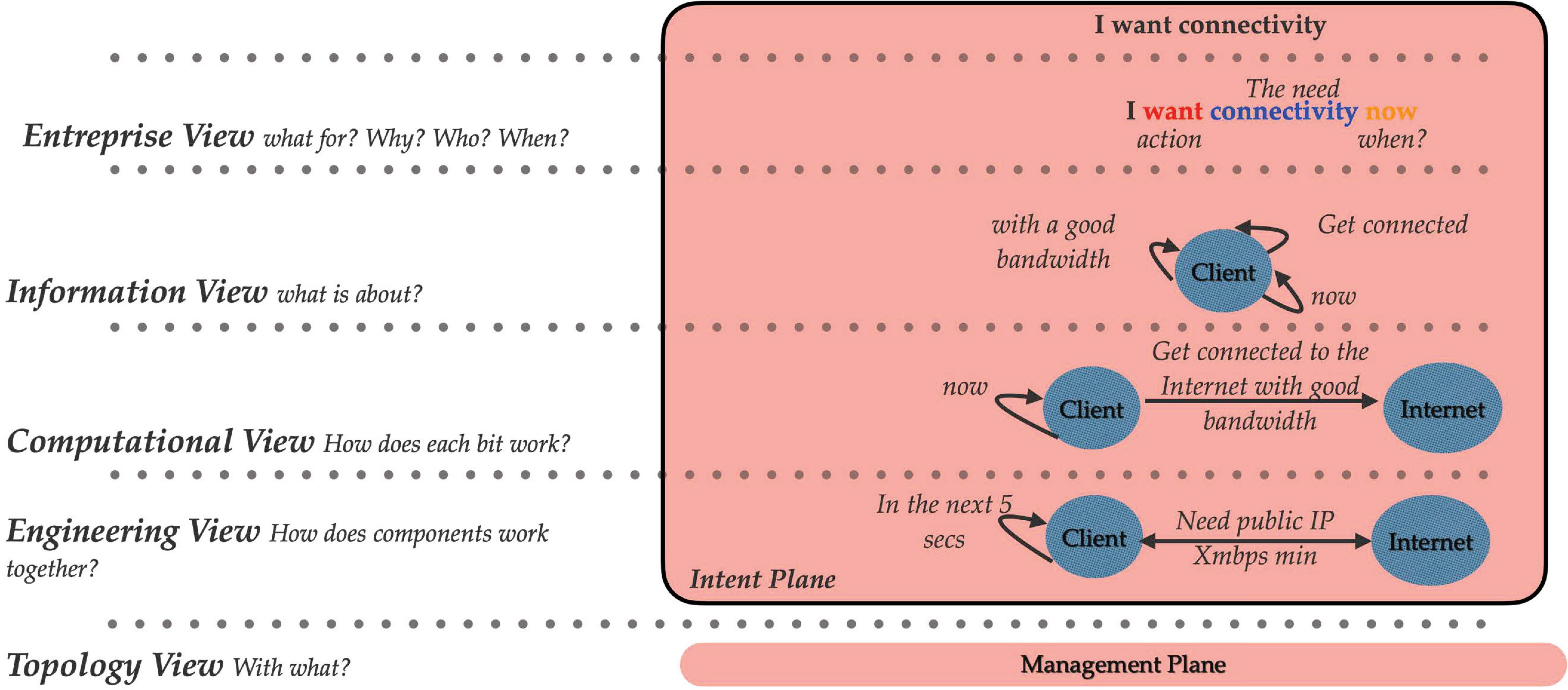
Figure 6 Example of multi-layer intent system.
In order to have a better idea about the intent multi-layer, we present, in Figure 6, a simple example of how intent can be translated from high-level requests to more in detailed demand. We used for this example a graph representation, but we could use any other tool. Let us assume that the intent is “I want connectivity”. The first layer (enterprise view) is about what for? Why? Who? When? Once the initial intent goes through an NLP process, we know that the action is “want”, the need is “connectivity” and the when is “now”. In the information view, we represent the intent graphically, where the client is characterized by a node. The more we go down, the more the graph becomes specific. We end up with a graph, where the client and the Internet are represented by nodes linked by a bidirectional arrow defining the public IP address and the minimum bandwidth needed.
• Intent Framework
As described in Section 4.1, the automated and knowledge-based network management architecture consists of several planes including the intent plane. In this section, we introduce an IBN framework by describing the intent plane and different interactions with other planes. Figure 7 introduces a high-level IBN framework.
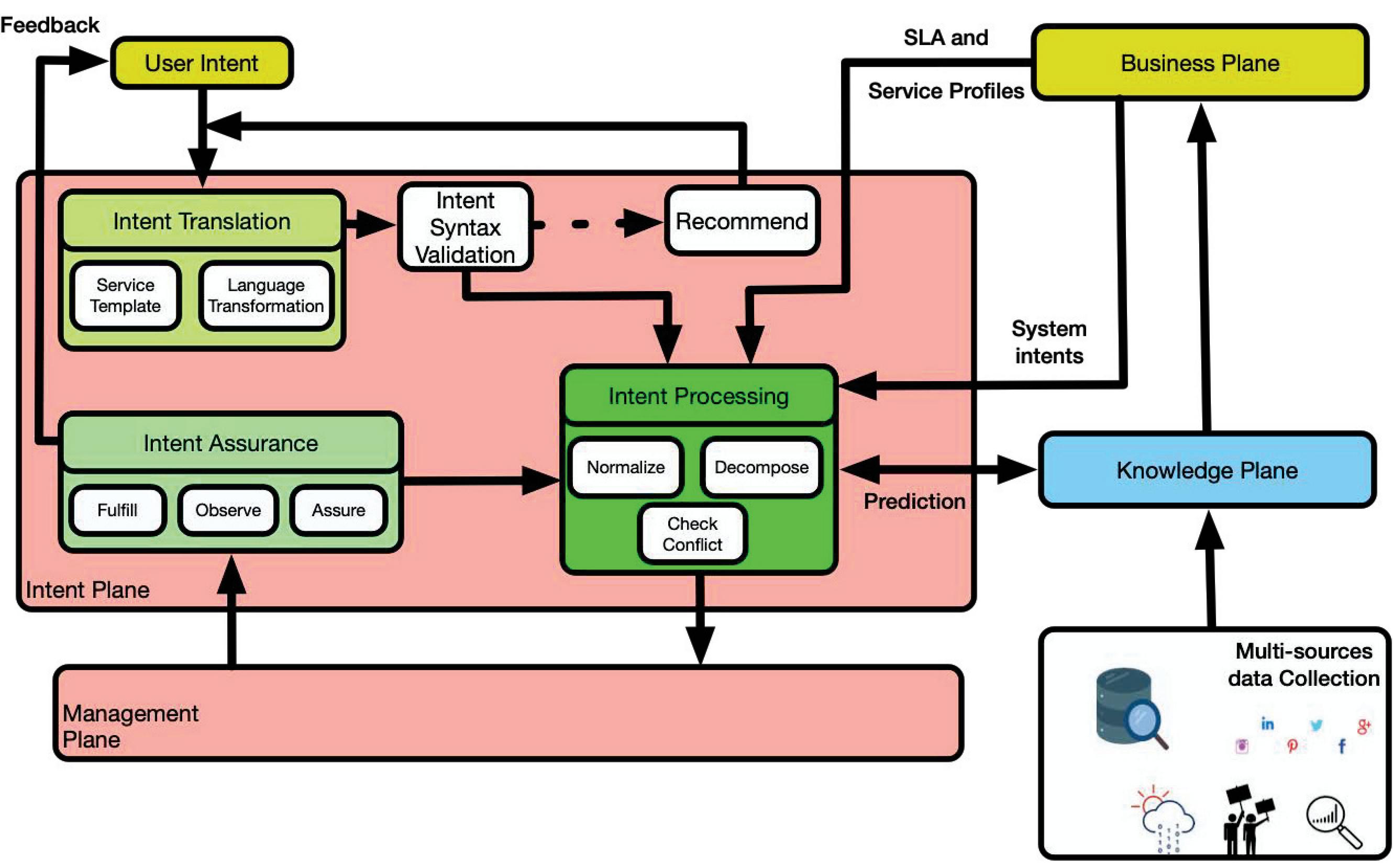
Figure 7 A Framework of intent-based networking.
The Intent Plane is decomposed into four main modules that translate, validate, decompose the original intent into network tasks, and keep track of its fulfillment once it is handed to the management plane.
• Intent Translation
When an intent is exposed to the intent plane, the first module that deals with it is the “Intent Translation”. Intent translation consists of mapping the intent from a certain high-level form to a more system-oriented request. This process can be done through a service template or a sort of language transformation.
When an intent is exposed to the intent plane, the first module that deals with it is the “Intent Translation”. Intention translation consists of mapping the intent from a certain high-level form to a more system-oriented request. This process can be done through a service template or a sort of language transformation.
• Intent Validation
The “Intent Validation” module checks the syntax of the transformation and if everything is understandable to the system. If it is not the case, it can recommend a new syntax to the intent’s originator. This micro-loop is the first control point to make sure that the intent can be processed correctly.
• Intent Processing
Once the intent is validated, the “Intent Processor” takes into account the SLAs and service profiles (from the business plane) to normalize the intent and decompose it into small network tasks. It also checks if there are any conflicts with existing intents. The intent processing module interacts with the knowledge plane to analyze if any improvement can be done.
• Intent Assurance
The “Intent assurance” module fulfills, observes, and assures in realtime whether the final result of the user’s intent execution in network infrastructure meets the user’s expectation. The intent assurance module interacts with the intent processing module and the service manager (from the management plane) in a closed-loop process of monitoring, tracking, diagnosing, and restoring based on user intents.
4.1.2 Multi-sources data collection
Instrumentation is one of the most important processes in our framework, which feeds the knowledge plane that will be described in the next section. We do not mean here only the traditional data collected from the data plane (legacy NMS and SDN controllers) but a cross-source data collection. In fact, on top of the traditional “network” data, we aim to use external data such as weather events, societal behaviors, political decisions, and so forth (Figure 8). One of the challenges here is to know what data to collect that might be beneficial to the system? How to collect that we do not interfere with the normal system operations? And find the correlations between different data sources.
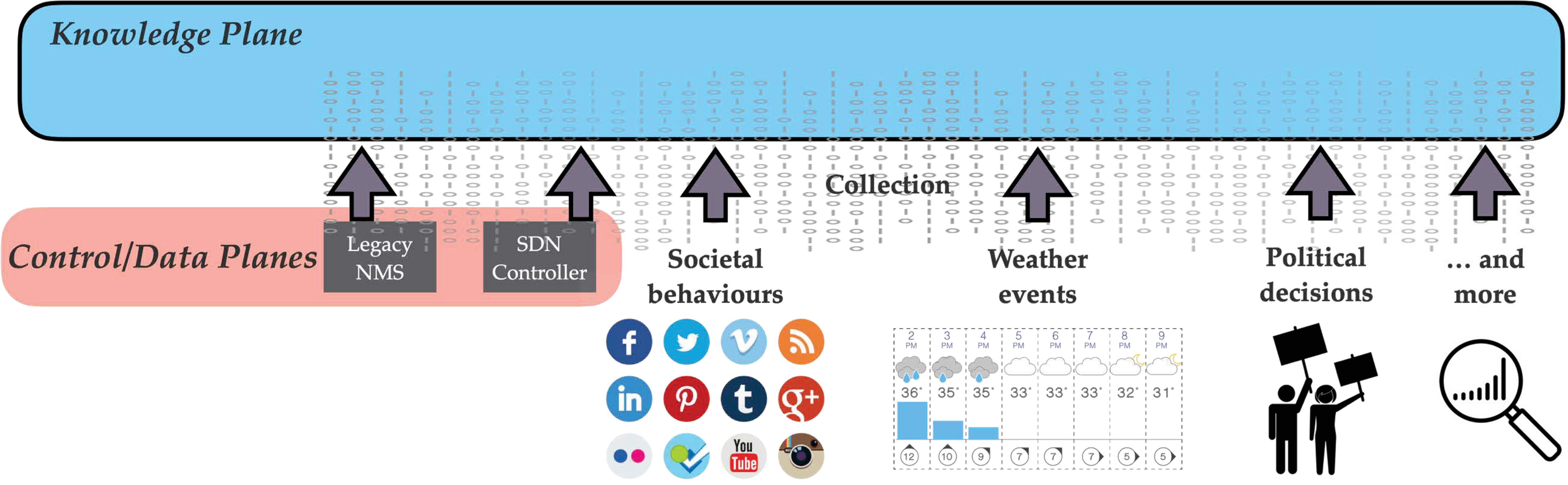
Figure 8 Instrumentation – cross-source data collection.
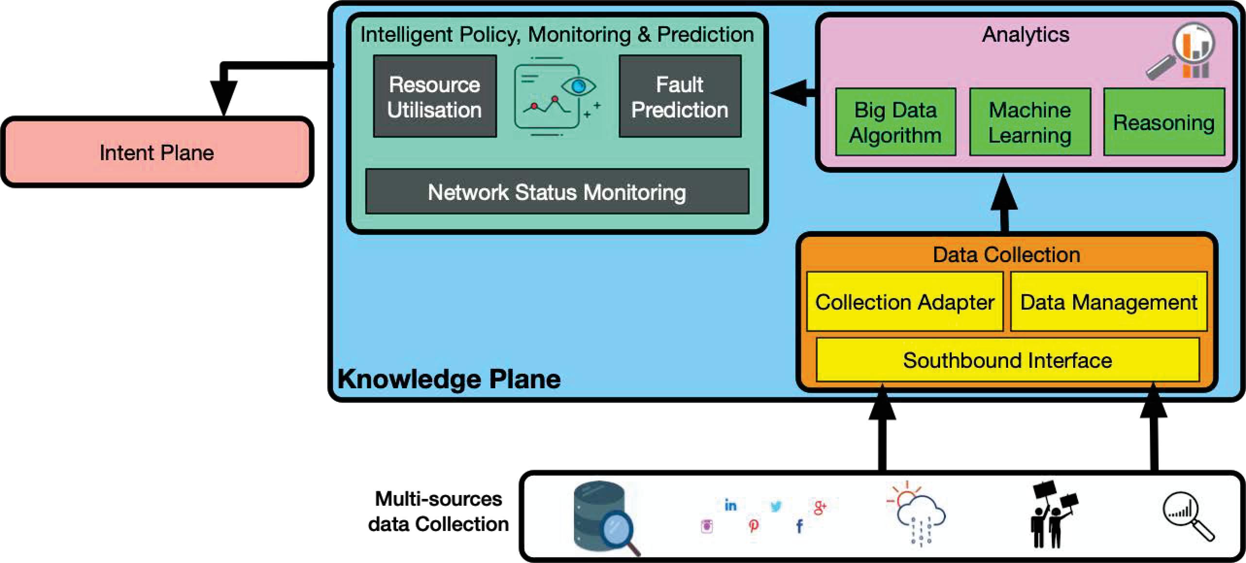
Figure 9 Knowledge plane.
4.1.3 Knowledge plane
As described earlier in the document, the knowledge plane uses multi-sources data collection as an input to provide predictions and/or solutions. The knowledge plane is formed by three blocks (Figure 9).
• Data collection block:
Once the data arrives at the knowledge plane from different sources, the data collection block processes it by filtering, adapting, and managing it. In fact, as the data is arriving from different sources, the first step is to clean the data from any residual information and classify it for the next block.
• Analytics block:
The huge amount of classified data needs to be processed. In the analytics block, we use big data algorithms, machine learning, and some reasoning to analyze the data by source but also as a whole to see if combining two sources can bring any useful information.
• Intelligent policy, monitoring and prediction block:
All the magic happens in this block. In fact, collecting data from the data plane gives us good knowledge about resource utilization and network status. Adding to this the analyzed data and system policies, this block will provide fault prediction, network improvement, and eventually can generate self-intents.
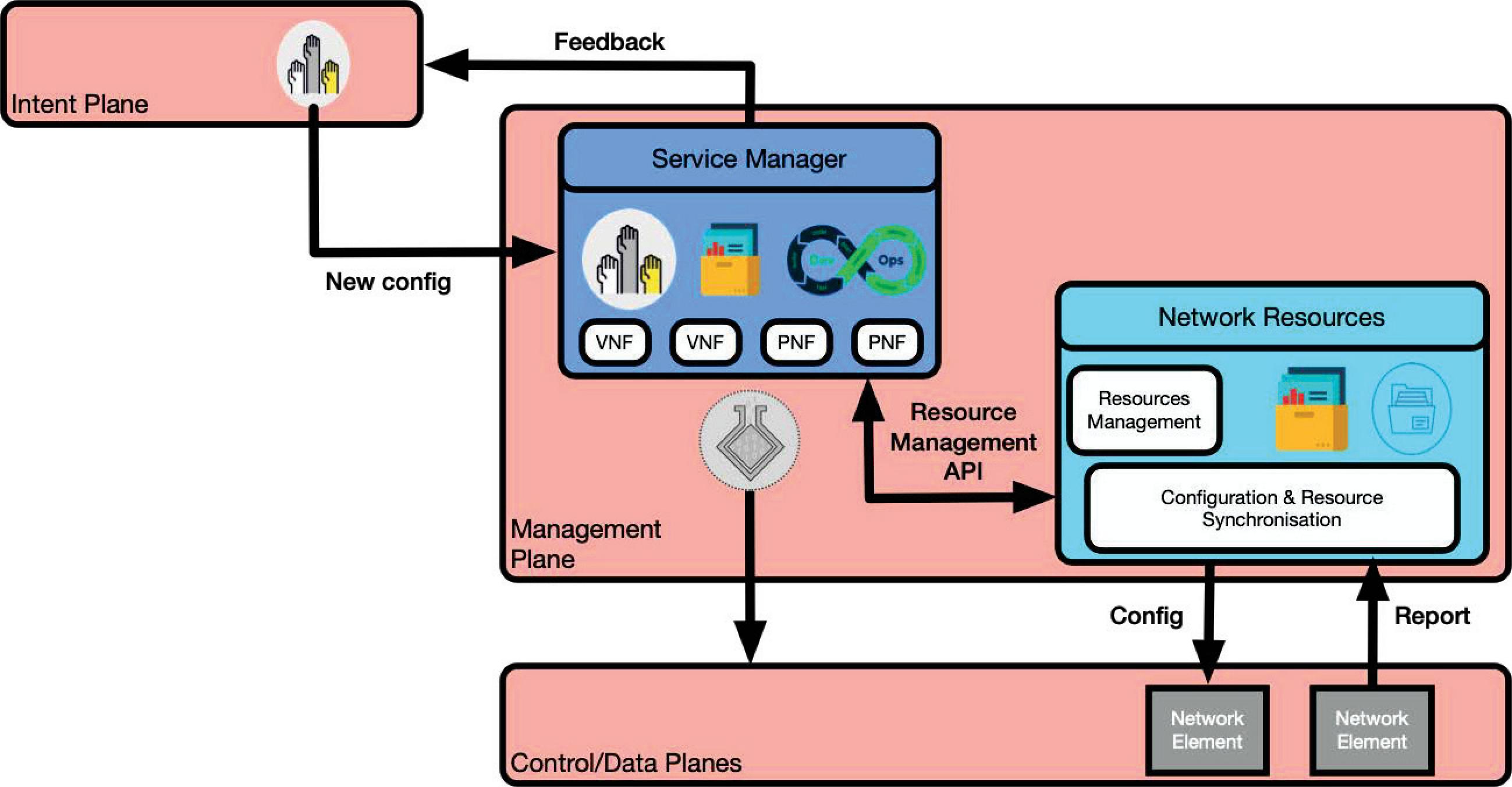
Figure 10 Management plane.
4.1.4 Management plane
It should be noted that the original intent will traverse through different layers during its process inside the intent plane, then it is released to the management plane. The management plane is formed by two main modules that make sure that the new intent has enough available resources to run correctly and without affecting existing already running intents (Figure 10).
• Network Resources
The “Network Resources” module collects live data from the network elements and lists an up to date inventory of all available resources in the system. It communicates this information with the service manager through the resource management API, which helps the service manager to allocate properly the available resources for new requests.
• Service Manager
Using the available resources (from the network resources module) and DevOps techniques like continuous integration continuous deployment (CI/CD), the “Service Manager” module creates a virtual real-time representation of the physical assets and builds, and deploys virtually the new configurations (that answer the intent). Finally, it tests to be sure that the configuration is bug-free and the output satisfies the requested intent. The new configuration is pushed for real deployment if all the tests pass.
4.1.5 Business plane
In our framework, the business plane represents the network’s operator, in our case BT. It communicates existing SLAs and service profiles to the intent processing module in order to ensure that the new intents are not impacting the existing SLAs. From all information/predictions received from the knowledge plane, it also can generate and inject low-level intent to the system.
4.2 Self-Intent Operational Loop
As highlighted in Figure 11, the operational loop of self-generated intent. In fact, when an intent is formulated by a human-being, the intent is mapped into something more technical and is checked against available resources (maintained by the management plane). On top of the user-intent, the system itself collects data from multiple sources and uses some machine learning or deep learning to extract any useful information. The system itself can generate and inject a self-generated intent if it detects any kind of network improvement or fault detection [9].
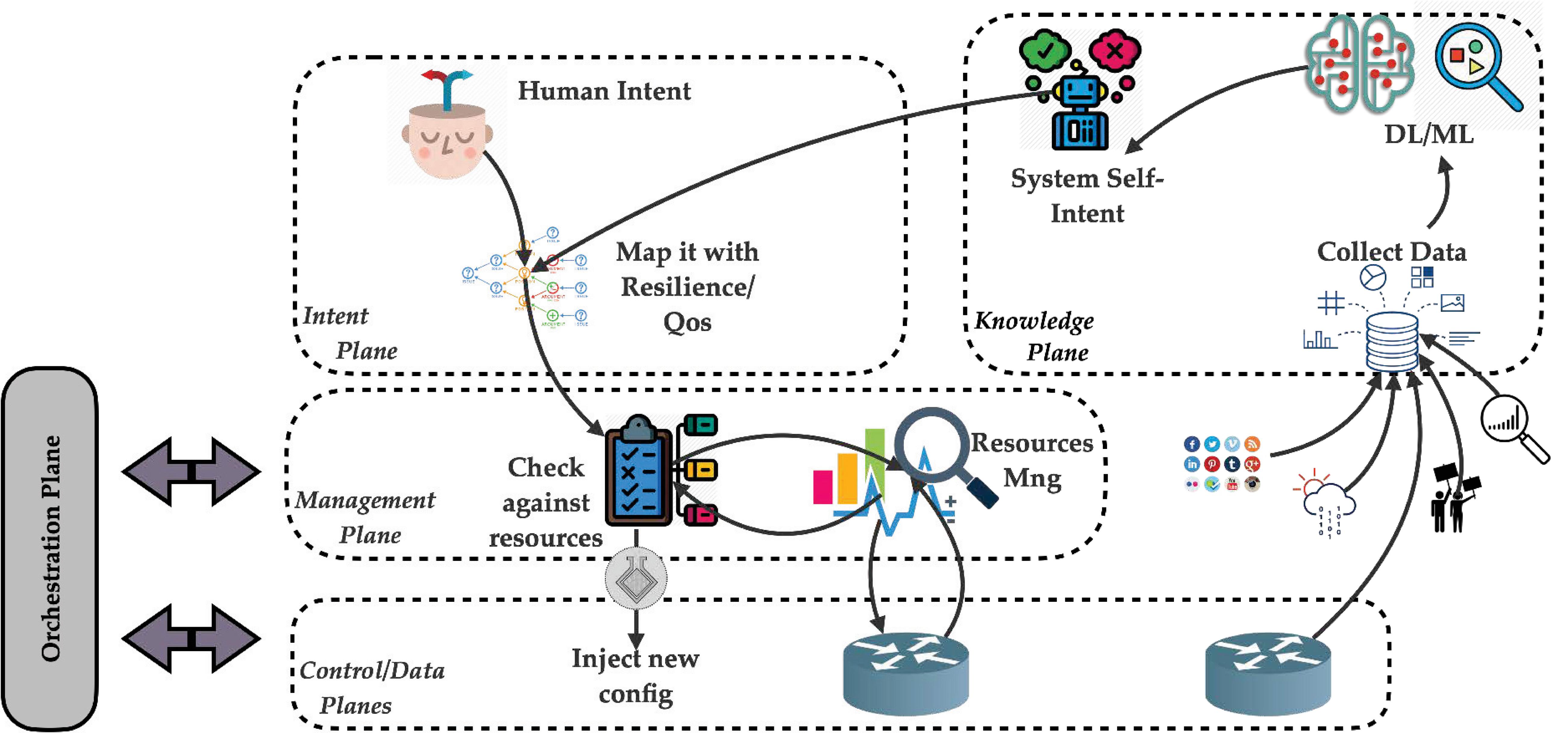
Figure 11 Self-Intent operational loop.
5 Conclusion
We know that the sustained growth of the Internet will continue, and the types and numbers of devices are rapidly expanding. The path towards autonomic networking started many years ago, but it is only recently that several factors have combined to accelerate the pace to enable the design and deployment of genuinely autonomic network devices in operator environments and underpinned by commercial pressures.
The framework and phases outlined in this paper, along with the recursive capabilities, use a “business aim” that derives the overall autonomic decision-making process via the following five stages: Creation; Automatic Operation; Self-Learning; System Protection; and Second Loop Learning. Each phase of the autonomic process will require distinct time-horizons, together with appropriate functional logic, and a collaborative loop to link with the previous stage.
The next step for this framework and its approach to autonomic networking is the application and extraction of results for the use case of self-adaptation. We intend to show how self-organization mechanisms in our framework may be applied to the operator network environment.
Further steps will consist of identifying and improving on observed shortcomings in the use case experiments, followed by building more ambitious use cases in order to expand the scope of, and confidence in, our system.
Acknowledgment
The authors gratefully acknowledge the support of the Next Generation Converged Digital Infrastructure (NG-CDI) Prosperity Partnership project funded by UK’s EPSRC and British Telecom plc.
References
[1] S. Dobson, S. Denazis, A. Fernández, D. Gaïti, E. Gelenbe, F. Massacci, P. Nixon, F. Saffre, N. Schmidt and F. Zambonelli. A Survey of Autonomic Communications. ACM Trans. Auton. Adapt. Syst., 1(2):223–259, Dec 2006.
[2] Next Generation Converged Digital Infrastructure project – https://www.ng-cdi.org/
[3] M. Bezahaf, D. Hutchison, D. King and N. Race. Internet Evolution: Critical Issues. Proceedings of the IEEE, 24(4):5–14, Jul 2020.
[4] S. Dobson, D. Hutchison, A. Mauthe, A. Schaeffer-Filho, P. Smith and J. P. G. Sterbenz. Self-Organization and Resilience for Networked Systems: Design Principles and Open Research Issues. Proceedings of the IEEE, 107(4):819–834, 2019.
[5] O. Babaoglu, M. Jelasity and A. Montresor. Grassroots approach to self-management in large-scale distributed systems. In Unconventional Programming Paradigms. Lecture Notes in Computer Science, vol. 3566:286–296, 2005.
[6] O. Babaoglu, M. Jelasity, A. Montresor, A. Fetzer, C. Leonardi, S. Van Moorsel and M. Van Steen. Self-star properties in complex information systems, conceptual and practical foundations. Lecture Notes in Computer Science, vol. 3460, 2005.
[7] D. Clark, C. Partridge, J. Ramming and J. Wroclawski. A knowledge plane for the internet. In Proceedings of the 2003 conference on Applications, technologies, architectures, and protocols for computer communications (SIGCOMM ’03), 3–10, 2003.
[8] ITU-T Technical Specification. Network 2030 Architecture Framework FG-NET2030 – Focus Group on Technologies for Network 2030, Jun 2020.
[9] M. Bezahaf, M. Perez Hernandez, L. Bardwell, E. Davies, M. Broadbent, D. King and D. Hutchison. Self-Generated Intent-Based System. 2019 10th International Conference on Networks of the Future (NoF), 138–140, Feb 2020.
[10] Y. Wang, R. Forbes, U. Elzur, J. Strassner, A. Gamelas, H. Wang, S. Liu, L. Pesando, X. Yuan and S. Cai. From Design to Practice: ETSI ENI Reference Architecture and Instantiation for Network Management and Orchestration Using Artificial Intelligence. in IEEE Communications Standards Magazine, 4(3):38–45, Sep 2020.
[11] R. Li, Z. Zhao, X. Zhou, G. Ding, Y. Chen, Z. Wang and H. Zhang. Intelligent 5G: When Cellular Networks Meet Artificial Intelligence. in IEEE Wireless Communications, 24(5):175–183, Oct 2017.
[12] Tayeb Ben Meriem, Ranganai Chaparadza, Benoît Radier, Said Soulhi, José-Antonio Lozano López and Arun Prakash. GANA–Generic Autonomic Networking Architecture: Reference Model for Autonomic Networking, Cognitive Networking, and Self-Management of Networks and Services. ETSI White Paper 16 (2016).
[13] M. Behringer, M. Pritikin, S. Bjarnason, A. Clemm, B. Carpenter, S. Jiang, and L. Ciavaglia. Autonomic Networking: Definitions and Design Goals. RFC 7575, Jun 2015.
Biographies

Mehdi Bezahaf is a Senior Research Associate at Lancaster University. He received his Ph.D. degree from Sorbonne Université in 2010. With a demonstrated history of working in academia and industry, his research interests include experimental networking, mobility management, wireless networks, Internet architecture, and network virtualization. Mehdi is also an active researcher and contributor to open Internet standards, including the IRTF, IETF, and ITU.

Stephen Cassidy MA MInstP CEng FIET is a Senior Manager at BT Applied Research, interested in the relationship between people, information technology and organisational structure, and how they determine enterprise culture and effectiveness. This combines research into AI, data-driven decision tools, self-learning systems, human behaviour and culture. He lectures on MBA programmes and serves on several advisory boards. He has published over 60 papers, holds a similar number of patents, and is a winner of the Queen’s Award for Industry.

David Hutchison is Professor of Computing at Lancaster University, UK, and the Founding Director of InfoLab21. His work is well known internationally for contributions in a range of areas including Quality of Service, active and programmable networking, content distribution networks, and testbed activities. His current research focuses on the resilience of networked computer systems, and the protection of critical infrastructures and services.

Daniel King is a Senior Research Associate at Lancaster University. He holds a PhD and MBA from Lancaster University. He worked previously for leading technology companies including Cisco, Redback Networks, Movaz Networks, and he co-founded Aria Networks. Daniel is also an active leader, researcher and contributor to open Internet standards, including the Internet Research Task Force (IRTF), the Internet Engineering Task Force (IETF), the Open Networking Foundation (ONF), and MEF.

Nicholas Race is a Professor of networked systems with the School of Computing and Communications, Lancaster University. His research is broadly around experimental networking and networked media, specializing in the use of software-defined networking and network-functions-virtualization for new network-level services, including in-network media caching, network-level fairness, and network monitoring.

Charalampos Rotsos received the Ph.D. degree from the Computer Laboratory, Cambridge University. He is a Lecturer in computer networks and networked systems with Lancaster University. His research focus is in network service management and orchestration, network programmability and monitoring, and cloud operating systems. He is an active contributor to many popular open-source projects relevant to SDN experimentation (OFLOPS), open-hardware (Blueswitch),and cloud OS (Mirage Unikernel).
Journal of ICT Standardization, Vol. 9_2, 229–256. River Publishers
doi: 10.13052/jicts2245-800X.928
This is an Open Access publication. © 2021 the Author(s). All rights reserved.