The 5G System Architecture
Frank Mademann
Chairman of 3GPP SA2, Huawei Technologies, Germany
E-mail: frank.mademann@huawei.com
Received 28 April 2018;
Accepted 3 May 2018
Abstract
This article provides an introduction to the 3GPP 5G system architecture and highlights its key features and characteristics.
Keywords
- 3GPP
- System Architecture
- 5G
1 Introduction
The milestone of defining the 3GPP 5G system architecture was achieved at the end of 2017. Within two years the 3GPP 5G architecture work progressed from the study period in 2016 to the delivery of a complete set of stage 2 level specifications. By achieving this milestone in 3GPP Release 15 the 5G system architecture has been defined – providing 3GPP’s 5G phase 1 set of features and functionality needed for deploying a commercially operational 5G system. The overall 5G system architecture details features, functionalities and services including dynamic system behaviour defined by information flows.
This article offers a brief introduction to the 5G system architecture, highlighting some of its main characteristics. It was first published at 3GPP.org in December 2017. The complete description is provided by the 3GPP specifications TS 23.501 [1], TS 23.502 [2] and TS 23.503 [3].
These 5G stage 2 level specifications include the overall architecture model and principles, support of broadband data services, subscriber authentication and service usage authorization, application support in general, but also specifically support for applications closer to the radio as with edge computing. Its support for 3GPP’s IP Multimedia Subsystem includes also emergency and regulatory services specifics. Further, the 5G system architecture model uniformly enables user services with different access systems, like fixed network access or interworked WLAN, from the onset. The system architecture provides interworking with and migration from 4G, network capability exposure and numerous other functionalities.
2 Service Based Architecture
Compared to previous generations the 3GPP 5G system architecture is service based. That means wherever suitable the architectural elements are defined as network functions that offer their services via interfaces of a common framework to any network functions that are permitted to make use of these provided services. Network Repository Functions (NRF) allow every network function to discover the services offered by other network functions. This architectural model, which further adopts principles like modularity, reusability and self-containment of network functions, is chosen to enable deployments to take advantage of the latest virtualization and software technologies. The related service based architecture figures of TS 23.501 [1] depict those service based principles by showing the network functions, primarily Core Network functions, with a single interconnect to the rest of the system. Reference point based architecture figures are also provided by the stage 2 specifications, which represent more specifically the interactions between network functions for providing system level functionality and to show inter-PLMN interconnection across various network functions. In the context of 3GPP specifications Public Land Mobile Network (PLMN) is typically denoting a network according to the 3GPP standard. The various architecture figures can be found in [1].
Figure 1 shows one of the service based architecture figures, which is for a roaming scenario with local breakout, i.e. the roaming UE interfaces the Data Network (DN) in the visited network (VPLMN) and the home network (HPLMN) enables it with subscription information from Unified Data Management (UDM), Authentication Server Function (AUSF) and UE specific policies from Policy Control Function (PCF). Network Slice Selection Function (NSSF), Access control and Mobility management Function (AMF), data Session Management Function (SMF) and Application Functions (AF) are provided by the VPLMN. The user plane provided via User Plane Functions (UPF) is managed following a model of control and user plane separation similar to what was already introduced in the latest 3GPP 4G release. Security Edge Protection Proxies (SEPP) protect the interactions between PLMNs. For more details and other scenarios see [1].
In the local breakout scenarios a UE receives the services of a PLMN typically completely from the serving operator’s administrative domain. Home-routed data services are the alternative for roaming scenarios, which have also network functions from the home operator’s administrative domain involved and the UE interfaces the DN in the HPLMN.
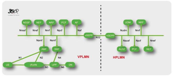
Figure 1 A service based architecture figure [1].
Service based principles apply between the control plane network functions of the Core Network. Further, the 5G system architecture allows network functions to store their contexts in Data Storage Functions (DSF). Functionality for releasing the UE specific Access Network – Core Network transport associations from one AMF and re-binding with another AMF enables separating such data storage also for the AMF. Earlier system architectures had more persistent UE specific transport associations, which made it more complex to change the UE’s serving node that compares to an AMF. The new functionality simplifies changing the AMF instance that serves a UE. It also supports increasing AMF resilience and load balancing as every AMF from a set of AMFs deployed for the same network slice can handle procedures of any UE served by the set of AMFs.
3 Common Core Network
The generalised design of the functionalities and a forward compatible Access Network – Core Network interface enable the 5G common Core Network to operate with different Access Networks. In 3GPP Release 15 these are the 3GPP defined NG-RAN and the 3GPP defined untrusted WLAN access. Studies on other access systems that may be used in future releases started already. The 5G system architecture allows for serving both Access Networks by the same AMF and thereby also for seamless mobility between those 3GPP and non-3GPP accesses. The separated authentication function together with a unified authentication framework are for enabling customization of the user authentication according to the needs of the different usage scenarios, e.g. using different authentication procedures per network slice. Most of the other 5G system architecture functionality introduced by this article is common for different Access Networks. Some functionality provides variants that are more suitable for specific Access Networks, like certain Quality of Service (QoS) functionality described later.
4 Network Slicing
A distinct key feature of the 5G system architecture is network slicing. The previous generation supported certain aspects of this with the functionality for dedicated Core Networks. Compared to this 5G network slicing is a more powerful concept and includes the whole PLMN. Within the scope of the 3GPP 5G system architecture a network slice refers to the set of 3GPP defined features and functionalities that together form a complete PLMN for providing services to UEs. Network slicing allows for controlled composition of a PLMN from the specified network functions with their specifics and provided services that are required for a specific usage scenario.
Earlier system architectures enabled typically rather a single deployment of a PLMN to provide all features, capabilities and services required for all wanted usage scenarios. Much of the capabilities and features provided by the single, common deployment was in fact required for only a subset of the PLMN’s users/UEs. Network slicing enables the network operator to deploy multiple, independent PLMNs where each is customized by instantiating only the features, capabilities and services required to satisfy the subset of the served users/UEs or a related business customer needs.
The very abstract representation in Figure 2 shows an example of a PLMN deploying four network slices. Each includes all what is necessary to form a complete PLMN. The two network slices for smart phones demonstrate that an operator may deploy multiple network slices with exactly the same system features, capabilities and services, but dedicated to different business segments and therefore each possibly providing different capacity for number of UEs and data traffic. The other slices present that there can be differentiation between network slices also by the provided system features, capabilities and services. The M2M network slice could, for example, offer UE battery power saving features unsuitable for smartphone slices, as those features imply latencies not acceptable for typical smart phone usages.
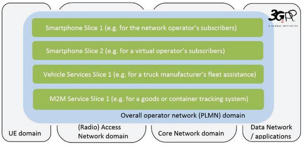
Figure 2 Abstract representation of a network deploying network slices.
The service based architecture together with softwarization and virtualization provides the agility enabling an operator to respond to customer needs quickly. Dedicated and customized network slices can be deployed with the functions, features, availability and capacity as needed. Typically, such deployments will be based on a service level agreement. Further, an operator may benefit by applying virtualization, platforms and management infrastructure commonly for 3GPP-specific and for other network capabilities not defined by 3GPP, but that a network operator may need or want to deploy in his network or administrative domain. This allows for a flexible assignment of the same resources as needs and priorities change over time.
Deployments of both the smaller scope of the 3GPP defined functionality and the larger scope of all that is deployed within an operator’s administrative domain are both commonly termed a “network”. Because of this ambiguity and as the term “slicing” is used in industry and academia for slicing of virtually any kind of (network) resources, it is important to emphasize that the 3GPP system architecture specifications define network slicing only within the scope of 3GPP specified resources, i.e. that what specifically composes a PLMN. This doesn’t hinder a PLMN network slice deployment from using e.g. sliced transport network resources. Please note, however, that the latter is fully independent of the scope of the 3GPP system architecture description. Pursuing the example further, PLMN slices can be deployed with as well as without sliced transport network resources.
Figure 3 presents more specifics of 3GPP network slicing. In that figure, network slice #3 is a straightforward deployment where all network functions serve a single network slice only. The figure also shows how a UE receives service from multiple network slices, #1 and #2. In such deployments there are network functions in common for a set of slices, including the AMF and the related policy control (PCF) and network function services repository (NRF). This is because there is a single access control and mobility management instance per UE that is responsible for all services of a UE. The user plane services, specifically the data services, can be obtained via multiple, separate network slices. In the figure, slice #1 provides the UE with data services for Data Network #1, and slice #2 for Data Network #2. Those slices and the data services are independent of each other apart from interaction with common access and mobility control that applies for all services of the user/UE. This makes it possible to tailor each slice for e.g. different QoS data services or different application functions, all determined by means of the policy control framework.
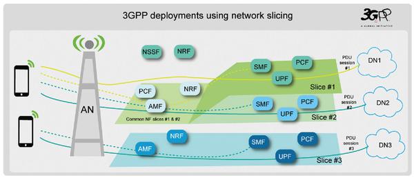
Figure 3 Network functions composing network slices.
5 Application Support
Data services are the basis of the application support. Compared to earlier generations data services offer considerably more flexibility for customization. A main part of this is the new QoS model of the 3GPP 5G system architecture, shown in Figure 4, which enables differentiated data services to support diverse application requirements while using radio resources efficiently. Service Data Flows (SDF) denote user plane data that certain QoS rules apply to. The actual description of SDFs is using SDF templates. Further, the QoS model is designed to support different Access Networks, including fixed accesses where QoS without extra signaling may be desirable. Standardized packet marking informs QoS enforcement functions what QoS to provide without any QoS signaling. While the option with QoS signaling offers more flexibility and QoS granularity. Furthermore, symmetric QoS differentiation over downlink and uplink is supported with minimal control plane signaling by the newly introduced Reflective QoS.
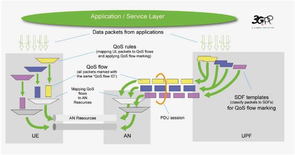
Figure 4 QoS model.
A large part of the functionality providing data connectivity is for supporting flexible deployment of application functions in the network topology as needed for edge computing, which is supported, for example, via three different Session and Service Continuity (SSC) modes or via the functionality of Uplink Classifiers and Branching Points.
The different SSC modes are sketched in Figure 5. The SSC modes include the more traditional mode (SSC 1), where the IP anchor remains stable to provide continual support of applications and maintenance of the path towards the UE as its location is updated. The new modes allow for relocating the IP anchor. There are two options, make-before-break (SSC mode 3) and break-before-make (SSC mode 2). The architecture enables applications to influence selection of suitable data service characteristics and SSC mode.
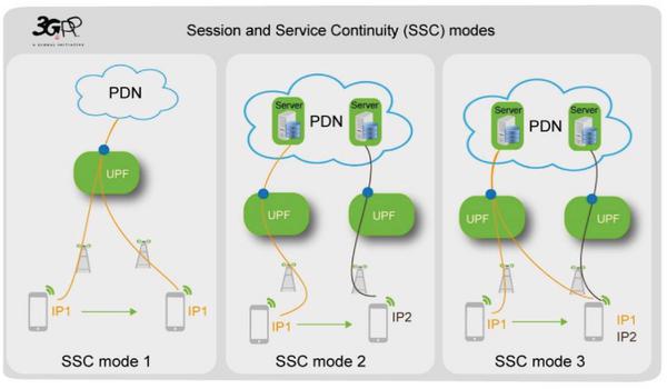
Figure 5 Session and Service Continuity modes.
As 5G network deployments are expected to serve huge amounts of mobile data traffic, an efficient user plane path management is essential. The system architecture defines in addition to the SSC modes the functionality of Uplink Classifiers and Branching Points to allow for breaking out and injecting traffic selectively to and from application functions on the user plane path before the IP anchor. Also, as permitted by policies, application functions may coordinate with the network by providing information relevant for optimizing the traffic route or may subscribe to 5G system events that may be relevant for applications.
6 Continuation of the work
The delivered stage 2 level specifications define the 3GPP 5G system from an overall, architectural perspective. The related work in the RAN, security, OAM and CT working groups continued with some specific stage 2 level aspects and with delivering stage 3 level specifications until June 2018.
This article has highlighted some of the most important advances of the 3GPP system architecture introduced with Phase 1 of 5G. Further advances and enhancements will be introduced in coming releases. Studies concerning Phase 2 functionality of 5G have already begun.
Specification work in 3GPP is a continuous process. More and up-to-date information can be found at 3GPP.org.
References
[1] 3GPP TS 23.501 – System Architecture for the 5G System; Stage 2.
[2] 3GPP TS 23.502 – Procedures for the 5G System; Stage 2.
[3] 3GPP TS 23.503 – Policy and Charging Control Framework for the 5G System; Stage 2.
7 Biography

Frank Mademann started his career with research and development on GSM circuit switched data services in 1991. This was also his initial work in ETSI SMG, which changed with the begin of standardization for GPRS. Since then he was involved in design and definition of all packet domain architectures and services that were specified by SMG and 3GPP. This includes GPRS from the very beginning as well as the packet domains of UMTS and LTE/SAE.
Frank has been working in the telecom and mobile industries for more than twenty years. He has been actively involved in the Architecture Working Group of 3GPP since 1999, where he is recognized as a key contributor to technical aspects of all packet domain architectures that were specified by SMG and 3GPP and also contributing to leadership and organizational matters. Having held earlier the position of a Vice Chair, he is the Chairman of 3GPP’s Architecture Working Group since 2015.
Journal of ICT, Vol. 6_1&2, 77–86. River Publishers
doi: 10.13052/jicts2245-800X.615
This is an Open Access publication. © 2018 the Author(s). All rights reserved.