3GPP 5G Security
Anand R. Prasad1, Sivabalan Arumugam2, Sheeba B3 and Alf Zugenmaier4
1Chairman of 3GPP SA3, NEC Corporation, Japan
2,3NEC Technologies India Pvt. Ltd., India
4Vice Chairman of 3GPP SA3 & Rapporteur, Munich University of Applied Sciences, Germany
E-mail: anand@bq.jp.nec.com; sivabalan.arumugam@india.nec.com; sheeba.mary@india.nec.com; alf.zugenmaier@hm.edu
Received 30 March 2018;
Accepted 3 May 2018
Abstract
5G is the next generation of mobile communication systems. As it is being finalized, the specification is stable enough to allow giving an overview. This paper presents the security aspects of the 5G system specified by the 3rd Generation Partnership Project (3GPP), especially highlighting the differences to the 4G (LTE) system. The most important 5G security enhancements are access agnostic primary authentication with home control, security key establishment and management, security for mobility, service based architecture security, inter-network security, privacy and security for services provided over 5G with secondary authentication.
Keywords
- LTE
- 5G
- 5G Core
- NR
- Authentication
- Services
- Security
- Privacy
1 Introduction
The 5G system is an evolution of the 4G mobile communication system, i.e. System Architecture Evolution/Long Term Evolution (SAE/LTE). Accordingly, the 5G security architecture has been designed to integrate 4G equivalent security into the 5G system. In addition, reassessment of other security threats such as attacks on radio interfaces, signalling plane, user plane, masquerading, privacy, replay, bidding down, man-in-the-middle, service based interfaces (SBI), and inter-operator network security have led to integration of further security mechanisms. This paper gives an overview of the security in phase 1, also called release 15 in 3GPP, and highlights the security features and security mechanisms offered by the 5G system, and the security procedures performed within the 5G System including the 5G Core (5GC) and the 5G new radio (NR), i.e. the 5G radio interface.
The paper starts by laying out the underlying trust models in 5G system considering roaming and non-roaming cases in Section 2 along with a brief summary on 5G key hierarchy. The enhancements in authentication and privacy are dealt with in Section 3. Section 4 discusses the multiple registration scenarios of User Equipment (UE) considering different cases such as same Public Land Mobile Network (PLMN) and different PLMN scenarios. The mobility procedures and intra-/inter-network security are discussed in Sections 5 and 6 respectively. The role of secondary authentication in services security is briefed in Section 7. Section 8 discusses the security aspects of network interconnects and Section 9 elaborates the migration and interworking security. Finally the paper is concluded in Section 10.
2 Evolution of the Trust Model
In the new 5G system, trust within the network is considered as decreasing the further one moves from the core. This has impact on decisions taken in 5G security design thus we present the trust model in this section, at the beginning fo the paper, together with the 5G key hierarchy.
2.1 Trust Model
The trust model in the user equipment (UE) is reasonably simple: there are two trust domains, the tamper proof universal integrated circuit card (UICC) on which the the Universal Subscriber Identity Module (USIM) resides as trust anchor. Mobile Equipment (ME) and the USIM together form the UE.
The network side trust model for roaming and non-roaming cases are shown in Figures 1 and 2 respectively, which shows the trust in mulitple layers, like in an onion.
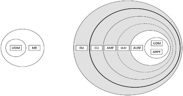
Figure 1 Trust model of non-roaming scenario.
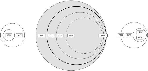
Figure 2 Trust model of roaming scenario.
The Radio Access Network (RAN) is separated into distributed units (DU) and central units (CU) – DU and CU together form gNB the 5G base-station. The DU does not have any access to customer communications as it may be deployed in unsupervised sites. The CU and Non-3GPP Inter Working Function (N3IWF – not shown in the figures), which terminates the Access Stratum (AS) security, will be deployed in sites with restricted access to maintenance personnel.
In the core network the Access and Mobility Management Function (AMF) serves as termination point for Non-Access Stratum (NAS) security. Currently, i.e. in the 3GPP 5G Phase 1 specification [2], the AMF is collocated with the SEcurity Anchor Function (SEAF) that holds the root key (known as anchor key) for the visited network. The security architecture is defined in a future proof fashion, as it allows separation of the security anchor from the mobility function in a future evolution of the system architecture.
In the roaming architecture, the home and the visited network are connected through SEcurity Protection Proxy (SEPP) for the control plane of the internetwork interconnect. This enhancement is done in 5G because of the number of attacks coming to light recently such as key theft and re-routing attacks in SS7 [16] and network node impersonation and source address spoofing in signalling messages in DIAMETER [17] that exploited the trusted nature of the internetwork interconnect [18]. Authentication Server Function (AUSF) keeps a key for reuse, derived after authentication, in case of simultaneous registration of a UE in different access network technologies, i.e. 3GPP access networks and non-3GPP access networks such as IEEE 802.11 Wireless Local Area Network (WLAN). Authentication credential Repository and Processing Function (ARPF) keeps the authentication credentials. This is mirrored by the USIM on the side of the client, i.e. the UE side. The subscriber information is stored in the Unified Data Repository (UDR). The Unified Data Management (UDM) uses the subscription data stored in UDR and implements the application logic to perform various functionalities such as authentication credential generation, user identification, service and session continuity etc. Over the air interface, both active and passive attacks are considered on both control plane and user plane. Privacy has become increasingly important leading to permanent identifiers being kept secret over the air interface.
2.2 Key Hierarchy
The long term secret key (K) provisioned in the USIM and the 5G core network acts as the primary source of security context in the same way as in of an 4G system. Different to LTE, in 5G there are 2 types of authentication, primary authentication that all devices have to perform for accesing the mobile network services, and secondary authentication to an external data network (DN), if so desired by the external data network.
After a successful primary authentication between the UE and the network, the serving network specific anchor key (KSEAF) is derived from K. From the anchor key, confidentiality and integrity protection keys are derived for NAS signalling and the AS consisting of control plane (CP), ie. radio resource control (RRC) messages, and user plane (UP). The key hierarchy of 5G is shown in Figure 3. The key hierarchy includes K, Cipher Key (CK) and Integrity Key (IK), KAUSF, KSEAF, KAMF, KNASint, KNASenc, KN3IWF, KgNB, KRRCint, KRRCenc, KUPint and KUPenc.
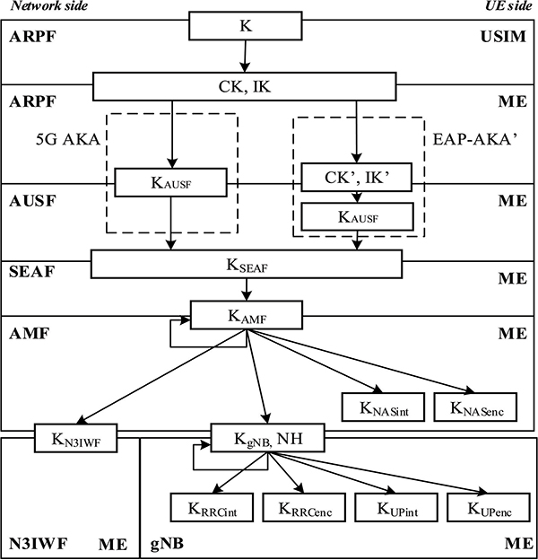
Figure 3 Key hierarchy.
The KAUSF is derived by ME and ARPF from CK and IK during 5G Authentication and Key Agreement (AKA). If the 3GPP credential K is used for authentication over a radio access technology supporting the extensible authentication protocol EAP, KAUSF is derived by ME and AUSF according to the EAP AKA’ specification. From KAUSF, the AUSF and ME derive the anchor key KSEAF that is then used to derive the KAMF by ME and SEAF. The K’AMF is a key that can be derived by ME and AMF from previous KAMF when the UE moves from one AMF to another during inter-AMF mobility. The integrity and confidentiality keys, KNASint and KNASenc respectively, are derived by ME and AMF from KAMF for the NAS signalling protection. The KgNB is derived by ME and AMF from KAMF. The KgNB is also derived by ME and source gNB using a intermediary key, KgNB*, during mobility that can lead to, what is known as, horizontal or vertical key derivation. The integrity and confidentiality keys for AS, i.e. UP (KUPint and KUPenc) and RRC (KRRCint and KRRCenc), are derived by ME and gNB from KgNB. UP integrity protection is another enhancement in 5G that is valuable for the expected Internet of Things (IoT) services. The intermediate key NH is derived by ME and AMF to provide forward secrecy during handover.
3 Access and Authentication
Network access in 5G network supports privacy of the permanent identifier to attackers on the air interface. This was not available in past generations of mobile neworks. In this section we discuss privacy in 5G and authentication. We do not discuss Security Mode Command (SMC) for AS and NAS.
3.1 Overview
Access to the network requires subscriber authentication, which is done by primary authentication mechanism in 5G system. So that the network can identify the subscriber, the UE has to send the subscription permanent identifier (SUPI in 5G). This permanent subscription identifier was sent in clear until 4G leading to various privacy related attacks.
In 5G privacy is achieved, even before authentication and key agreement, by encrypting the SUPI before transmitting using a HN public key which is stored in the USIM. Although specified, privacy enablement is under the control of the home network of the subscriber. Privacy in 5G is elaborated in Section 3.2. Up to 4G, the home network had to trust the visited network through which the authentication took place. Subsequent procedures such as location updates or submission of Customer Data Records (CDRs) would need to be taken at face value. This lead to fraud cases impacting operator’s revenue. Another case is the fraudulent registration attempt by an attacker to register the subscriber’s serving AMF in UDM when UE is not present in the serving AMF. To resolve these issues, in 5G the concept of increased home control was introduced, where the home network receives proof of UE participation in a successful authentication.
3.2 Privacy
The subscription identifier SUPI, see Figure 4, contains sensitive subscriber as well as subscription information thus it should not be transferred in clear text except for parts necessary for proper functioning of the system, i.e. routing information in the form of Mobile Country Code (MCC) and Mobile Network Code (MNC). As explained in 3.1, the subscriber privacy enablement is under the control of the home network of the subscriber. Note that in case of unauthenticated emergency calls, privacy protection is not required. So as to provide privacy the UE generates and transmits the Subscription Concealed Identifier (SUCI1) using a protection scheme, i.e. one of the Elliptic Curve Integrated Encryption Scheme (ECIES) profiles, with the public key that was securely provisioned in control of the home network.
The UE constructs the SUCI from the protection scheme identifier, the home network public key identifier, the home network identifier and the protection scheme-output that represents the output of a public key protection scheme. The SUCI will contain routing information in the clear, which is the mobile network and mobile country code of the home network, as well as potentially some routing information within the home network, where the home network is so large that it needs to be segmented. At the home network de-conealment of the SUPI from SUCI is done by the Subscription Identifier De-concealing Function (SIDF) that is located at the ARPF/UDM. To meet the LI requirements along with privacy, binding of SUPI to the derivation of the KAMF is done.
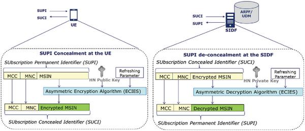
Figure 4 SUPI structure and concealed sensitive information.
3.3 Authentication Procedure In 5G System
EAP-AKA’ and 5G AKA are mandatory 5G primary authentication methods. Other EAP based authentication methods can be used optionally as well. For the purpose of explanation we have divided the authentication steps in two phases, see Figure 5. Phase 1 is initiation of 5G authentication and authentication method selection. Phase 2 is mutual authentication between the UE, subscription, and the network.
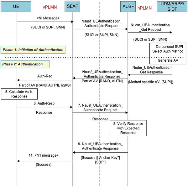
Figure 5 Message exchanges involved in 5G authentication procedure.
During phase 1, the UE sends a registration request (N1 message) to the SEAF that contains a concealed identifier SUCI or 5G-Globally Unique Temporary UE Identity (5G-GUTI) where, as the name suggests, 5G-GUTI is a temporary identity assigned by the network during a previous session. On receiving a registration request from the UE the SEAF sends an authentication request (Nausf_UEAuthentication_Authenticate Request) message to the AUSF with the serving network name (SNN) [2] and either SUPI, if available and 5G-GUTI is valid, or SUCI. The SNN is a concatenation of service code and the Serving Network Identity (SN Id). Upon receiving the authentication request, the AUSF checks whether the requesting SEAF is authorized to use the SNN which is a form of home control in 5G. If the serving network is not authorized to use the SNN, the AUSF respond with “serving network not authorized” in the authentication response (Nausf_UEAuthentication_Authenticate Response). The authentication information request (Nudm_UEAuthentication_Get Request) from AUSF to UDM/ARPF/SIDF includes the SUCI or SUPI and the SNN. SIDF is invoked to de-conceal the SUPI from SUCI. Based on SUPI and the subscription data, the UDM/ARPF choose the authentication method to be used.
In phase 2, on selection of authentication methods, mutual authentication takes place. The authentication procedure involved in 5G, see Figure 5, is briefly explained in the following steps for both EAP-AKA’ and 5G AKA.
Authentication Vector (AV) generation:
EAP-AKA’: The authentication procedure is followed as discussed in RFC 5448 [9] except the authentication vector (AV) derivation at the UDM/ARPF. The UDM/ARPF first generates an AV with AMF separation bit = 1 [8] and generates CK’ and IK’ from CK, IK and SNN. The UDM/ARPF subsequently sends this transformed AV (RAND, AUTN, XRES, CK’, IK’) to the AUSF with an indication that the AV is to be used for EAP-AKA’.
5G AKA: The UDM/ARPF derives the KAUSF from CK, IK and SNN and generates the 5G Home Environment AV (5G HE AV) where the 5G HE AV contains the RAND, AUTN, XRES*, and KAUSF. 5G HE AV is sent to the AUSF in the authentication information Request Response (Auth-info Resp) message. The AUSF stores the KAUSF and XRES* until expiry.
- The AUSF derives the KSEAF (anchor key) from KAUSF and sends the Challenge message to the SEAF in a Nausf_UEAuthentication_Authenticate Response message with KSEAF, AUTN and RAND. In case of 5G AKA HXRES* is also sent.
- At receipt of the RAND and AUTN, the USIM computes a response RES and returns RES, CK, IK to the UE. In case of 5G AKA additionally the ME compute RES* from RES. The UE then sends the Challenge Response message to the SEAF in a NAS message Auth-Resp message.
- The SEAF forwards the Response Challenge message to the AUSF in Nausf_UEAuthentication_Authenticate Request message. In case of 5G AKA the SEAF computes HRES* from RES*, and compares HRES* with HXRES*. If the values are same, the SEAF considers the authentication as successful and sends the received RES*, in a Nausf_UEAuthentication_Authenticate Request message containing the SUPI or SUCI and the SNN, to the AUSF.
The AUSF verifies the message to support increased home control and if the verification is successfull, the AUSF acts according to the authentication method as explained below. Note that if the AUSF received SUCI from the SEAF, then the AUSF also includes the SUPI in 5G-Authentication Confirmation Answer message.
EAP-AKA’: The AUSF and UDM in the home network obtains confirmation that the UE has been successfully authenticated when the EAP-Response/AKA’-Challenge received by the AUSF has been successfully verified. The AUSF derives EMSK from CK’ and IK’ as described in RFC 5448. The AUSF then uses the first 256 bits of EMSK as the KAUSF and derives the anchor key KSEAF from KAUSF. The AUSF sends EAP Success message to the SEAF inside Nausf_UEAuthentication_Authenticate Response along with the KSEAF.
5G AKA: The AUSF compares the received RES* with the stored XRES* and if they are equal, the AUSF considers the confirmation message as successfully verified and indicates this to the SEAF. The AUSF and UDM in the home network obtains confirmation that the UE has been successfully authenticated.
- The SEAF sends the Success message to the UE in the N1 message.
- The SEAF then derives the KAMF from the KSEAF and the SUPI and send it to the AMF. On receiving the Success message, the UE derives KAUSF and KSEAF in the same way as the AUSF and derives the KAMF from the KSEAF and the SUPI. The SEAF provide the ngKSI and the KAMF to the AMF.
4 Multiple Registrations

Figure 6 5G supporting multiple NAS connections.
There are two cases as shown in Figure 6 where the UE can be registered in both a network accessed through 5G NR and simultaneously in network accessed through a non-3GPP radio access technology like WLAN. This can be in the same PLMN or in the different PLMN’s serving networks. The UE will establish two NAS connections with the network in both cases. This is called multiple registration
The first case is where the UE is registered with the same AMF in the same PLMN serving network over both 3GPP and non-3GPP accesses. A common NAS security context is created during the registration procedure over the first access type. In order to realize cryptographic separation and replay protection, the common NAS security-context will have parameters specific to each NAS connection. The connection specific parameters include a pair of NAS COUNTs for uplink and downlink and unique NAS connection identifier. The value of the unique NAS connection identifier is set to “0” for 3GPP access and set to “1” for non-3GPP access. The second case is when the UE is registered in one PLMN over a certain type of access (e.g. 3GPP) and is registered to another PLMN over the other type of access (e.g. non-3GPP). The UE independently maintains and uses two different 5G security contexts, one per PLMN. Each security context is established separately via a successful primary authentication procedure with the Home PLMN. All the NAS and AS security mechanisms defined for single registration mode are applicable independently on each access using the corresponding 5G security context.
5 Mobility
Depending on an operator’s security requirements, the operator can decide whether to have Xn or N2 handovers for a particular gNB according to the security characteristics of a particular gNB. Where Xn handover is handover over Xn interface without involvement of AMF and N2 handover involves the AMF. The 5G mobility scenarios are depicted in Figure 7 is briefed as follows.
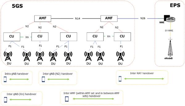
Figure 7 Oveview of 5G mobility scenario.
Xn-handover: The handover of UE from a source gNB to a target gNB over Xn is referred to as Xn-handover. The source gNB includes the UE 5G security capabilities in the handover request message containing the ciphering and integrity algorithms used in the source cell. The target gNB selects the algorithm with highest priority from the received 5G security capabilities of the UE according to the prioritized locally configured list of algorithms. The chosen algorithms are indicated to the UE in the Handover Command message if the target gNB selects different algorithms. If the UE does not receive any selection of integrity and ciphering algorithms, it continues to use the same algorithms as before the handover [2, 4]. In the Path-Switch message, the target gNB sends the UE’s 5G security capabilities received from the source gNB to the AMF. The AMF will verify that the UE’s 5G security capabilities received from the target gNB are the same as the UE’s 5G security capabilities that the AMF has locally stored. If there is a mismatch, the AMF will send its locally stored 5G security capabilities of the UE to the target gNB in the Path-Switch Acknowledge message. Additionally, the AMF may log the event and may take additional measures, such as raising an alarm.
N2-handover: The handover from a source gNB to a target gNB over N2 interface possibly including an AMF change is referred to as N2-handover or inter-AMF handover. For N2-handover, the source gNB includes AS algorithms used in the source cell in the source to target transparent container that is sent to the target gNB. The AS algorithms used in the source cell are provided to the target gNB so that it can decipher and integrity verify the RRCConnectionReestablishmentComplete message on Signalling Radio Bearer 1 (SRB1) in the potential RRC Connection Re-establishment procedure. The AMF should not initiate any of the N2 procedures including a new key towards a UE if a NAS Security Mode Command (SMC) procedure is ongoing with the UE. The AMF will not initiate a NAS SMC towards a UE if one of the N2 procedures including a new key is ongoing with the UE.
Intra-gNB-CU handover: This type of handover occurs in gNBs with split DU-CU, where the UE performs handover between DUs within a gNB-CU. It is not required to change the AS security algorithms during intra-gNB-CU handover as the security termination point remains the same. If the UE does not receive an indication of new AS security algorithms during an intra-gNB-CU handover, the UE can continue to use the same algorithms as before.
6 DU-CU Interface Security
The F1 interface [5, 6] between DU and CU could also be protected by NDS/IP [11, 12]. Messaging over F1 interface include control-plane (F1-C), management traffic and user-plane (F1-U). The security requirements for the F1 interface includes support of confidentiality, integrity and replay protection. It is expected that F1-U security is independent of F1-C or management traffic security, i.e. one could configure F1-U security differently than F1-U and management traffic security.
7 Services Security – Secondary Authentication
5G supports optional EAP based secondary authentication between the UE and an external data network (DN). Session Management Function (SMF) performs the role of the EAP Authenticator [14] and relies on an external DN-AAA server to authenticate and authorize the UE’s request for the establishment of a PDU sessions. See Figure 8 for secondary authentication procedure with the external DN-AAA server.
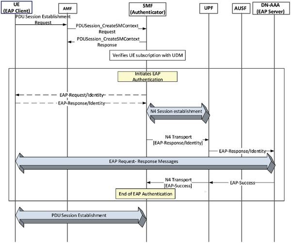
Figure 8 Secondary authentication.
As a pre-condition the UE is registered with the network performing primary authentication with the AUSF/ARPF and establishes a NAS security context with the AMF. The UE initiates establishment of a new PDU Session by sending an SM NAS message containing a PDU Session Establishment Request message to the AMF. The UE includes slice information (identified by S-NSSAI) and the PDN it would like to connect to (identified by DNN). The AMF sends the request to the SMF for PDU session establishment (Nsmf_PDUSession_CreateSMContext Request message) with SM NAS message, SUPI, the received S-NSSAI, and the DNN. The SMF sends an Nsmf_PDUSession_CreateSMContext Response message to the AMF. The SMF then obtains subscription data from the UDM for the given SUPI and verifies whether the UE request is compliant with the user subscription and with local policies. The SMF may also verify whether the UE has been authenticated and/or authorized by the same DN, as indicated DNN, or the same AAA server in a previous PDU session establishment. The SMF can skip the rest of the procedure if the verification is successful.
If the SMF finds that the UE has not been authenticated with the external DN-AAA server, then the SMF will trigger EAP Authentication to obtain authorization from an external DN-AAA server and sends an EAP Request/Identity message to the UE. The UE then send an EAP Response/Identity message with its DN-specific identity complying with Network Access Identifier (NAI) format. The DN AAA server and the UE can exchange EAP messages as required by the EAP method. EAP messages are sent in the SM NAS message between the UE and the SMF; The SMF communicates with the external DN-AAA via UPF using N4 and N6 interface [2]. After the completion of the authentication procedure, DN AAA server will send EAP Success message to the SMF. The SMF may save the UE ID and DNN (or DN’s AAA server ID if available) in a list for successful authentication/authorization between the UE and SMF. Alternatively, the SMF may update the list in UDM. If the authorization is successful, PDU Session Establishment proceeds according to TS 23.502 [10].
In case of roaming scenario, two SMFs such as visitor SMF (V-SMF) and home SMF (H-SMF) are involved, where H-SMF acts as the authenticator. Following the PDU Session Establishment Request message from the UE via AMF as discussed above, the V-SMF sends an Nsmf_PDUSession_Create Request to the H-SMF. To establish the requested PDU session after a successful EAP based secondary authentication, the H-SMF sends an Nsmf_PDUSession_Create Response to V-SMF with EAP Success and this message is inturn sent to the UE by the V-SMF.
8 Inter Operator Network Security
N32 interface provides inter operator network connectivity (see Figure 9) that might traverse over Internetwork Packet Exchange (IPX). To ensure interconnect security, the SEPP is introduced as an entity that resides at the perimeter of the PLMN. The SEPP implements application layer security for all the service layer information exchanged between two Network Functions (NFs) across two different PLMNs. On receiving service layer messages from a given NF, the SEPP protects the messages before sending them over the N32 interface. Similarly, on receiving a message over N32 interface the SEPP forwards the message to approproiate NF after security verification. The SEPP provides integrity protection, confidentiality protection of parts of message and replay protection. Mutual authentication, authorization, negotiation of cipher suites and key management are also parts of SEPP security functions. It also performs topology hiding and spoofing protection.
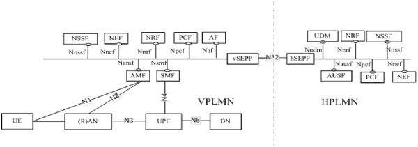
Figure 9 Interconnect security and SEPP.
9 Interworking Security
Since ubiquitous coverage of 5G will not be available from day-one, it is essential to provide 4G to 5G interworking solutions that give a migration path to stand-alone 5G network. There are two cases of interworking we discuss in this Section 1 Non-Stand Alone (NSA) case, this is discussed in detail here and 2 case where 5G stand-alone and 4G networks are connected to each other and UE moves between the networks, this case is briefly discussed.
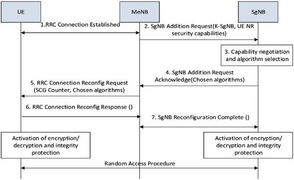
Figure 10 EN-DC procedure with SgNB encryption/decryption and integrity protection activation.
Several interworking scenarios are defined for 5G [7, 15]. These scenarios are also know as dual-connectivity since the UE connects with both NR and LTE. The starting step defined by 3GPP is NSA as depicted in Figure 10, this is also known as Option 3 or E-UTRA-NR Dual Connectivity (EN-DC), where both LTE (E-UTRA) and NR connects to the 4G core network. In case of NSA the UE and the Master eNB (MeNB) establish the RRC connection. The MeNB computes and delivers the KSgNB to the Secondary gNB (SgNB) along with the UE NR security capabilities in the SgNB addition request message. The UE also derives the same KSgNB. The MeNB checks whether the UE has 5G NR capabilities and access rights to SgNB. The SgNB selects the algorithm and notifies to the MeNB in SgNB addition request acknowledgement message. The MeNB sends the RRC Connection Reconfiguration Request with SCG Counter parameter to the UE instructing it to configure the new DRBs and/or SRB for the SgNB and compute the S-KgNB. The UE computes the S-KgNB and sends the RRC Reconfiguration Complete to the MeNB activating encryption/decryption and integrity protection. The MeNB then sends SgNB Reconfiguration Complete to the SgNB over the X2-C to inform the configuration result and following this, the SgNB can activate the chosen encryption/decryption and integrity protection with UE. Unlike dual connectivity in 4G network, RRC messages are exchanged between UE and SgNB, thus keys such as KSgNB-RRC-int as well as KSgNB-UP-enc used for integrity and confidentiality protection of RRC messages as well as UP are derived. Integrity protection for UP will not be used in EN-DC case. Use of confidentiality protection is optional for both UP and CP.
Security solution for mobility between 4G and 5G networks is similar to that specified for 4G [1, 19]. There are various situations such as state of device and security contexts available. Handover will happen between 4G and 5G incase UE is in active state. Identity, be it SUCI or temporary identity, and key identity of security context will be used to locate the security context in the network and derive a mapped security context (KAMF to KASME for 5G to 4G or vice versa) for secure service continuity. For idle mode mobility mapped context could be used else existing context, if existing, will be activated. Mapped context is basically derivation of say 4G key from 5G.
10 Near Future
NSA and 5G Phase-1 gives us a taste of the new generation with mobile broadband. The next step will be solutions for IoT covering several scenarios in the form of massive Machine Type Communication (mMTC) and Ultra-Reliable and Low Latency Communications (URLLC). Where mMTC relates to very large number of devices transmitting a relatively low volume of non-delay-sensitive data and URLLC relates to services with stringent requirements for capabilities such as throughput, latency and availability.
For (mMTC) very low data-rates, going down to few bits per day, we will have to consider the extent of security (be it authentication, confidentiality, integrity or otherwise) that can be provisioned. Several IoT or Machine-to-Machine (M2M) services and devices fall under this category, examples are temperature sensors giving hourly updates, sensors on farm animals giving vital signature couple of times a day etc. Such devices will also be resource constrained in terms of battery, computation and memory. This brings us to several requirements on security like complete security related message sequence, e.g. authentication, should not run for every communication and even when run, they should be performed with minimum payload and round-trip. Other requirement will be to reduce security related bits, e.g. integrity, for every communication. Security and cryptographic algorithms must be energy efficient and optimized to work for resource constrained devices.
On the other end (URLLC) are high data-rate devices with potentially higher battery and computational resources; examples include cars, Industrial IoT (IIoT) devices like machineries in factories and virtual or augmented reality (VR or AR) devices used for gaming or real-time services. Provisioning of higher data rates also means that complexity of security functions should be considered to avoid processing delay. At the same time, higher data rates are provisioned by decreasing the overhead bits in radio interface that in turn has implications on bits that can be budgeted for security.
11 Conclusion
Overview of 5G Phase-1 security requirements and solutions is presented in this paper. Major differences from 4G security are the trust model, key hierarchy, security for inter-operator network, privacy and service based architecture security. Current specification supports security for 4G to 5G migration and interworking with 4G. The 5G phase 2 specifications will provide enhanced security for scenarios covered by mMTC and URLLC.
References
[1] 3GPP TS 33.401, “Technical Specification Group Services and System Aspects: 3GPP System Architecture Evolution (SAE) Security architecture”, Release 15, v 15.3.0, March 2018.
[2] 3GPP TS 33.501, “Security architecture and procedures for 5G system”, Release 15, v 15.0.0, March 2018.
[3] 3GPP TS 24.501, “Non-Access-Stratum (NAS) protocol for 5G System (5GS)”, Release 15, v 1.0.0, March 2018.
[4] 3GPP TS 38.331, “NR-Radio Resource Control (RRC) protocol specification”, Release 15, v 15.0.0, March 2018.
[5] 3GPP TS 38.470, “NG-RAN: F1 general aspects and principles”, Release 15, v 15.0.0, March 2018.
[6] 3GPP TS 38.472, “NG-RAN: F1 signalling transport”, Release 15, v 15.0.0, December 2017.
[7] 3GPP TS 36.300, “Evolved Universal Terrestrial Radio Access (E-UTRA) and Evolved Universal Terrestrial Radio Access Network (E-UTRAN) - Overall description”, Release 15, v 15.0.0, March 2018.
[8] 3GPP TS 33.102, “3G Security - Security architecture”, Release 14, v 14.1.0, March 2017.
[9] RFC 5448, “Improved Extensible Authentication Protocol Method for 3rd Generation Authentication and Key Agreement (EAP-AKA’)”, Nokia, May 2009.
[10] 3GPP TS 23.502, “Procedures for the 5G System”, Release 15, v 15.1.0, March 2018.
[11] 3GPP TS 33.210, “3G security; Network Domain Security (NDS); IP network layer security”, Release 14, v 14.0.0, December 2016.
[12] RFC-7296, “Internet Key Exchange Protocol Version 2 (IKEv2)”.
[13] RFC-7321: “Cryptographic Algorithm Implementation Requirements and Usage Guidance for Encapsulating Security Payload (ESP) and Authentication Header (AH)”.
[14] RFC-3748: “Extensible Authentication Protocol (EAP)”.
[15] NEC White paper, “Making 5G a Reality”, 2018, https://www.nec.com/en/global/solutions/nsp/5g_vision/doc/wp2018ar.pdf.
[16] Tobias Engel. (December 2014). “SS7: Locate. Track. Manipulate”, http://berlin.ccc.de/∼tobias/31c3-ss7-locate-track-manipulate.pdf
[17] GSMA RIFS: “Diameter Roaming Security – Proposed Permanent Reference Document”.
[18] 3GPP TS 33.899, “Study on the security aspects of the next generation system”, Release 14, v 1.3.0, August 2017.
[19] Anand R. Prasad and Seung-Woo Seo, Security in Next Generation Mobile Networks: SAE/LTE and WiMAX, River Publishers, September 2011.
Biographies

Anand R. Prasad, Dr. & ir., Delft University of Technology, The Netherlands, is Chief Advanced Technologist, Executive Specialist, at NEC Corporation, Japan, where he leads the mobile communications security activity. Anand is the chairman of 3GPP SA3 (mobile communications security standardization group), a member of the governing body of Global ICT Standardisation Forum for India (GISFI), founder chairman of the Security & Privacy working group and a governing council member of Telecom Standards Development Society, India. He was chairman of the Green ICT working group of GISFI. Before joining NEC, Anand led the network security team in DoCoMo Euro-Labs, Munich, Germany, as a manager. He started his career at Uniden Corporation, Tokyo, Japan, as a researcher developing embedded solutions, such as medium access control (MAC) and automatic repeat request (ARQ) schemes for wireless local area network (WLAN) product, and as project leader of the software modem team. Subsequently, he was a systems architect (as distinguished member of technical staff) for IEEE 802.11 based WLANs (WaveLAN and ORiNOCO) in Lucent Technologies, Nieuwegein, The Netherlands, during which period he was also a voting member of IEEE 802.11. After Lucent, Anand joined Genista Corporation, Tokyo, Japan, as a technical director with focus on perceptual QoS. Anand has provided business and technical consultancy to start-ups, started an offshore development center based on his concept of cost effective outsourcing models and is involved in business development.
Anand has applied for over 50 patents, has published 6 books and authored over 50 peer reviewed papers in international journals and conferences. His latest book is on “Security in Next Generation Mobile Networks: SAE/LTE and WiMAX”, published by River Publishers, August 2011. He is a series editor for standardization book series and editor-in-chief of the Journal of ICT Standardisation published by River Publishers, an Associate Editor of IEEK (Institute of Electronics Engineers of Korea) Transactions on Smart Processing & Computing (SPC), advisor to Journal of Cyber Security and Mobility, and chair/committee member of several international activities.
He is a recipient of the 2014 ITU-AJ “Encouragement Award: ICT Accomplishment Field” and the 2012 (ISC)2 Asia Pacific Information Security Leadership Achievements (ISLA) Award as a Senior Information Security Professional. Anand is Certified Information Systems Security Professional (CISSP), Fellow IETE and Senior Member IEEE and a NEC Certified Professional (NCP).

Sivabalan Arumugam received Ph.D in Electrical Engineering from Indian Institute of Technology Kanpur, India in 2008 and M.Tech degree from Pondicherry University, India, in 2000. He has 14 years of experience in Academic teaching and Research. Presently he works as Assistant General Manager for Research at NEC Mobile Network Excellence Center (NMEC), NEC Technologies India Pvt Ltd, Chennai. Prior joining NECI he was associated with ABB Global Services and Industries Limited, Bangalore as Associate Scientist. He has published more than 25 papers in various International Journals and Conferences and also participated in many National and International Conferences. In his current role, he is representing NEC for Global ICT Standards forum of India (GISFI). His research interest includes Next Generation Wireless Networks.

Sheeba Backia Mary Baskaran received her Ph.D. in Faculty of Information and Communication Engineering from Anna University, Chennai in 2017. She received her M.E. degree in Computer science and engineering from Anna University, Coimbatore and received the B.Tech. degree in Information Technology from Anna University, Chennai. She was a member of NGNLabs Anna University and was a recipient of Maulana Azad National Fellowship from 2013–2016. She has 19 months of experience in Research and Development of mobile communication networks and security standardization. She is carrying out her research in Security Solutions for 5G, Internet of Things, Public Safety network and Common API Framework. Her research interest includes LTE, LTE-Advanced, 5G, IoT Security and MAC layer protocol design. She contributes to 3GPP SA3 standard Specifications and applied for more than 5 patents in next generation network security. She has authored over 10 publications in international journals (IEEE Access, ACM, Elsevier & Springer) and conferences. She is also a reviewer for IEEE Access and Elsevier journals.

Alf Zugenmaier is teaching mobile networks and security at the Munich University of Applied Sciences. He also represents NTT DOCOMO at the 3GPP security working group of which he is vice chair. He has been contributing to security standardization in 3GPP for ten years, supporting 4G and 5G security standardization. Prior to joining the University, he worked at DOCOMO Euro-labs in Munich, Germany, and Microsoft Research in Cambridge, UK. His areas of interest are network and systems security as well as privacy.
Journal of ICT, Vol. 6_1&2, 137–158. River Publishers
doi: 10.13052/jicts2245-800X.619
This is an Open Access publication. © 2018 the Author(s). All rights reserved.
1 SUCI is pronounced sushi.