“Cyber Parallel Traffic World” Cloud Service in 5G Mobile Networks
Received: October 17, 2014; Accepted: November 10, 2014
Yoshitoshi Murata1 and Shinya Saito2
- 1Professor, Faculty of Software and Information Science, Iwate Prefectural University, Takizawa, Iwate, Japan, y-murata@iwate-pu.ac.jp
- 2Graduate School of Software and Information Science, Iwate Prefectural University Graduate School, Japan, g231j017@s.iwate-pu.ac.jp
Abstract
Remarkable progress has been made in intelligent transportation systems. For example, autonomous vehicles can now detect their positions, as well as those of other vehicles, pedestrians, and obstacles. Pedestrians with smartphones can also determine their positions and send this information to the Internet. However, even though vehicles and pedestrians can instantly determine their positions, the information used for this purpose is rarely sent to a cloud service. Here, we propose a new cloud service, called “cyber parallel traffic world” (CPTW), in which vehicles, pedestrians, and temporary obstacles exist and move in synchronization with their real-world counterparts. In addition, virtual vehicles and pedestrians in the CPTW can communicate with real/virtual vehicles and pedestrians. The CPTW service could make driving safer and less stressful; provide people with experience in driving on roads throughout the world, etc. We describe how to construct its virtual world and establish communications.
Keywords
- ITS
- smart mobility
- cloud service
- safety drive
- virtual world
- 5G mobile networks
- Internet of Things
- IOT
1 Introduction
Remarkable progress has been made in intelligent transportation systems (ITSs). For example, autonomous vehicles can now detect their positions by using advanced global navigation satellite systems (GNSS). Moreover, they can detect other vehicles, pedestrians, obstacles, and traffic signals by using radar sensing, camera systems, and so on, and can drive themselves to the destinations specified by their drivers [1, 2]. Several of these capabilities, such as obstacle detection, have already been implemented in commercial vehicles. Information on the positions of vehicles and pedestrians can be gathered from optical beacons in the universal traffic management system (UTMS) and from roadside “ITS Spots” (communication units) and can be used to prevent traffic accidents, predict traffic flows, control vehicle movements, and so on [3–5]. In Toyota's vision of a “smart mobility society,” an inter-vehicle communication system provides every vehicle with communication links with the vehicles ahead and behind, enabling them to maintain a safe distance from each other. This will help to reduce traffic congestion and make travel safer and less stressful [6].
We proposed a cloud service, called “cyber parallel traffic world” (CPTW), for one of the future ITSs [7]. This service also would be one of the Internet of Things (IOT) [8, 9] which work on the 5G mobile networks. In the CPTW roads, sidewalks, and traffic facilities such as traffic signals are represented as they are in the real world. Vehicles, pedestrians, and temporary obstacles exist and move in synchronization with their real-world counterparts. Virtual vehicles can also be driven in CPTW as if they were in the real world represented in the cloud. The second feature is different from what is directly possible in the real world: vehicles, drivers and pedestrians can communicate with other vehicles, drivers, and pedestrians by pointing to their positions rather than referring to an ID (e.g., a telephone number or address). For example, drivers can communicate with pedestrians, by giving messages such as “Go ahead and cross the street”, and drive while talking with other drivers around them. Vehicles detect the positions of other vehicles and pedestrians, and avoid traffic congestion in CPTW. In addition, communications such as these enable the motions of the vehicles to be coordinated so as to reduce their emissions. This helps to make driving safer and less stressful.
We anticipate that a CPTW can be constructed using position information sent from the next generation mobile terminal, that is a successor of the smartphone, and vehicle navigation systems in the near future, and thus, it will not need information from proprietary traffic facilities such as UTMS optical beacons. This will make the CPTW system more cost effective than similar existing systems. The CPTW requires high-speed constant Internet connection, a flexible group communication and relay communication. However, even LTE, that is the latest mobile network, does not provide either group communications or relay communications; its characteristic of the fast hand off would not be sufficient for the high-speed constant Internet connection [10]. We hope that 5G mobile networks or other networks will be able to provide the high-speed constant Internet connection and these communication forms.
We have already developed a method for constructing virtual roads and traffic signals and defining traffic rules for them. Three-dimensional models of roads and traffic signals are made from elemental data such as road width measurements stored in a database system of a client's mobile terminal or vehicle navigation system.
After discussing related work in Section 2, we describe the concept and features of CPTW in Section 3. The construction of roads and the establishment of traffic rules are explained in Section 4. The communication modes and development scheme are described in Section 5 and 6. The key points of this paper are summarized in Section 7.
2 Related Work
Since our proposal is related to ITS and 3D road modelling, we will describe representative technologies, i.e., UTMS, which embodies the latest ITS technologies, and Forum8's 3D road modelling system, called VR-Drive.
2.1 UTMS
Since many of the CPTW functions are the same as those in UTMS, we will start with an overview of UTMS [3, 4]. UTMS was developed by the UTMS Society of Japan, which has many Japanese manufacturers and organizations as members, to improve road traffic safety, smooth traffic flows, and ultimately harmonize road traffic with the environment so as to contribute to public welfare. UTMS provides nine main functions:
- The Integrated Traffic Control System (ITCS) uses technologies such as infrared beacons and computers to provide optimum signal control for effectively dealing with ever-changing traffic flow patterns and providing real-time traffic information.
- The Advanced Mobile Information System (AMIS) gathers real-time traffic information and provides it to drivers.
- The Public Transportation Priority System (PTPS) gives priority to public transportation by monitoring bus lanes, warning vehicles that are illegally using the bus lane, and pre-empting traffic signals.
- The Mobile Operation Control System (MOCS) helps transportation administrators manage their bus, freight, sanitation, and other operations.
- The Environment Protection Management System (EPMS) reduces traffic pollution (exhaust gas and noise) and thus helps protect the regional environment.
- The Driving Safety Support System (DSSS) helps drivers drive more safely by providing them with information gathered using various sensors that detect vehicles and pedestrians.
- The “Help system for Emergency Life saving and Public safety” (HELP) immediately reports position information to rescue organizations in the case of an emergency such as a traffic accident, vehicle breakdown, or sudden illness.
- The Pedestrian Information and Communication System (PICS) helps the elderly and the disabled to move around safely.
- The Fast Emergency Vehicle Pre-emption System (FAST) helps emergency vehicles reach an accident site as quickly as possible.
There are many functions in UTMS for improving traffic safety, smoothing traffic flow, and protecting the environment. However, the information used in it is mainly gathered using proprietary intelligent traffic facilities. Therefore, establishing a UTMS is expensive.
Autonomous vehicles can determine not only their own positions but also the positions of other vehicles, pedestrians, and obstacles. Pedestrians who have smartphones can also determine their positions. If this position information could be collected and presented in a simulated world, i.e., CPTW, on the Internet and if an inter-vehicle communication function were implemented, many of the UTMS functions described above could be provided at much lower cost.
2.2 Forum8's VR-Drive
The 3D modelling environment that we want should be able to extract road data, traffic rules data, etc., from real-world sources, put these data into road and traffic rules database, and create 3D roads, etc., by referring to these databases. The trouble is that most modelling tools can't extract the sort of data we need from real-world sources.
An exception is VR-Drive [11] developed by Forum8. This tool simulates real-world driving environments in every possible way, and includes, e.g., the traffic volume, pedestrians, cyclists, junctions, traffic lights, hills, holes, rail crossings, ITS road signs, and roundabouts. It is developed for addressing the following issues:
- Developing safe and eco-friendly driving schemes.
- Highlighting lapses of attention to improve drivers' awareness.
- Training drivers in special driving procedures.
- Examining the behaviour, specifically, the attention of drivers.
- Preparing drivers to face and anticipate any driving situation (e.g., accident scene, slippery road surface, etc.).
Forum8 provides road databases to create 3D road environments for Japan and several other countries.
Since the VR-Drive has many functions, it is one of best pieces of 3D road-environment software that could be chosen to complete CPTW. However, its license fee is expensive and its software is not open source. Therefore, we had to develop a new 3D road modelling software by ourselves.
3 Concepts and Features of the CPTW
Roads, traffic facilities, temporary obstacles, and sidewalks in the real world are represented as 2D or 3D models in CPTW as shown in Figure 1. There are also traffic rules, which are the same as in the real world, and it is possible to detect whether the corresponding real/virtual vehicles and pedestrians obey them. Data on the positions of pedestrians and vehicles detected by the next generation mobile terminals and vehicle navigation systems are sent to CPTW, where they are plotted in real time. Position data that other vehicles and intelligent traffic facilities detect are also plotted in real time. Virtual vehicles are also presented in a way that distinguishes them from the corresponding real-world vehicles. This feature would be useful, say, for people practicing driving in another country where they have had no experience driving. Moreover, a real/virtual driver and pedestrian can communicate with other drivers and pedestrians by pointing to a position on the vehicle navigation or the next generation mobile terminal screen, not an ID (e.g., phone number or address). This scheme is unlike existing communication schemes and has not been developed yet. People could construct a local CPTW for their place of residence. These local worlds could in turn be connected to create a larger and eventually global CPTW.
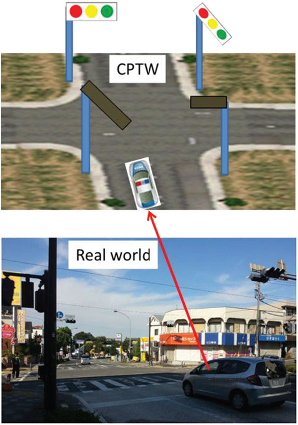
Figure 1 Images showing correspondence between CPTW and the real world
Such a global CPTW could assist drivers and pedestrians in several ways.
- They could be made aware of vehicles and pedestrians screened by obstacles.
- A real/virtual driver could see the environment of the road and roadside through a real vehicle's video camera.
- A real driver could send another real driver or pedestrian a message such as “Go ahead” or “Be careful a little way ahead.” Moreover, real/virtual drivers could drive a vehicle while talking with other real/virtual drivers. This would enable drivers to be more courteous.
- It is very difficult for a driver to keep his or her car in a lane during snowfalls or heavy rain at night. However, once the positional accuracy gathered in real-time can be made finer than a few tens of cm, a driver will be able to know how well his or her vehicle is keeping within a lane in such conditions.
- A virtual driver could gain experience driving on roads throughout the world by using CPTW as a driving simulator. This would be particularly useful to people planning to visit and drive in another country where they have had no experience driving.
- A real driver could be warned that she or he is approaching the scene of a traffic accident, enabling her or him to take appropriate action and avoid secondary accidents.
- Real vehicles could drive closer to one another, which would cut wind resistance and reduce fuel consumption.
4 Constructing the CPTW
We have to construct a virtual world encompassing all the roads, traffic facilities, and sidewalks throughout the real world. Real/virtual vehicles and pedestrians who are residents in the CPTW have to be plotted in this virtual world.
In this virtual world, it should be possible to detect whether a real/virtual vehicle or pedestrian is obeying the traffic rules of the corresponding country. These virtual structures can be constructed by extracting road data from maps covering the world, such as Google Maps and Google Earth, and by gathering the traffic rules for each country. These data would then be stored in a roads database and a rules database. An application program would create 2D/3D virtual roads by using data in the roads database and place traffic signals and signs in accordance with the rules in the traffic rules database, as shown in Figure 2 [12].
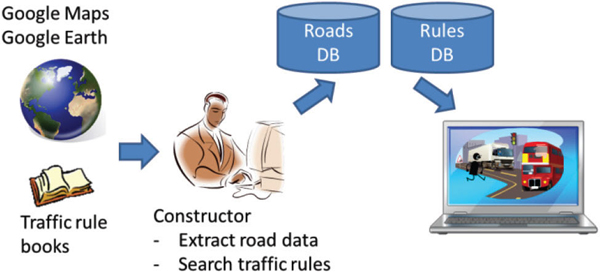
Figure 2 Overview of constructing CPTW
We used OpenGL as the 3D program interface and developed a program using the “glut,” “sdl”, “glew,” and “OpenAL” tools [13–15].
4.1 Roads
A road is represented as an approximate function for detecting whether a vehicle or pedestrian is obeying the traffic rules.
First, the simulation program finds the direction perpendicular to the parametric curve that expresses the centre line of the road in order to create the width of an approximated road. It then calculates the coordinates of a point shifted to the right or left of the centre line, as shown in Figure 3.
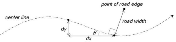
Figure 3 Method for creating 3D roads
The tangential angle at an arbitrary point on the curve can be calculated as
A point at the road edge is one that is shifted to the road edge from an arbitrary point (x, y) on the curve. Points (xr, yr) at the right side road edge and points (xl, yl) at the left side road edge can be calculated as
Wr is the width of the right side on the road and Wl is the one on the left. We use the 3D spline curve as an approximate function for roads except intersections. Since the 3D spline curves pass through the plotted points, as shown in Figure 4, it is easy to extract road data. Each part of 3D road polygons is created by changing the parameter “t” of the three-dimensional spline curve from zero to one, calculating many points on the road edge, and storing those points in a vertex array. Road centre lines and lane lines are created by changing the value of W in Equations (1) – (5).
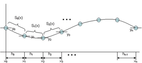
Figure 4 Three-dimensional spline curves on plotted points
When the width or number of lanes at t = 0 differs from that at t = 1, the simulation program decides that the road has a right- or left-turn-only lane. When a road has such a lane, the road width is gradually increased. The simulation program does this by calculating a smooth curve that represents increments in the lane width. A sigmoid function is used to increase the width. It is a monotonically increasing function and has one inflection point. Therefore, it is suitable for expressing a right- or left-turn-only lane. An example of a 3D straight road with an increasing number of lanes is shown in Figure 5 (a).

Figure 5 Examples of created 3D roads
Two-dimensional B-spline curves are used as functions for intersections. The polygon for an intersection consists of all curve functions that connect to the intersection. The parameter “t” of the calculated curve function is changed from zero to one in the same way as for a road, and an intersection polygon is created. An example of an intersection is shown in Figure 5 (b).
At least, following data have to be stored in the roads database.
[General roads]
- Road ID: identifies road
- 3rd coefficient of curve X
- 2nd coefficient of curve X
- 1st coefficient of curve X
- 0th coefficient of curve X
- 3rd coefficient of curve Y
- 2nd coefficient of curve Y
- 1st coefficient of curve Y
- 0th coefficient of curve Y
- Right-side width at t = 0
- Left-side width at t = 0
- Right-side width at t = 1
- Left-side width at t = 1
- Number of right-side lanes at t = 0
- Number of left-side lanes at t = 0
- Number of right-side lanes at t = 1
- Number of left-side lanes at t = 1
- ID of intersection at t = 0
- ID of intersection at t = 1
[Intersections]
- Intersection ID
- Curve ID
- 2nd coefficient of intersection curve X
- 1st coefficient of intersection curve X
- 0th coefficient of intersection curve X
- 2nd coefficient of intersection curve Y
- 1st coefficient of intersection curve Y
- 0th coefficient of intersection curve Y
Sidewalks are constructed by adding thickness to the road edge parameter in Equations (2) – (5). Roadside feature and traffic facilities other than signals, such as trees and lights lining a street, are created using 3D modelling tools and placed on sidewalks. Their positions are calculated using Equations (2) – (5)
4.2 Traffic Rules
The traffic rules are classified as either “unspecified rules,” such “keep to the right,” or “specified rules” derived from traffic signals and signs. The specified rules are stored in the rules database. The CPTW detects whether vehicles and pedestrians at an intersection or on a road under the control of a traffic signal and/or sign are obeying the rules. For example, a vehicle at an intersection where a “no turn on red” sign (Figure 6) is posted is checked to see whether it turns right when the controlling traffic signal is red.

Figure 6 Traffic sign for “No Turn on Red”
A scheme is used to relate traffic signals to the meanings of signs. The scheme has to handle traffic signals and rules worldwide.
We collected traffic rules and traffic signal definitions for three countries: Japan, the U.S., and Germany. The colors of signal lights and their basic meanings have been defined by the CIE (Commission Internationale de l'Éclairage) and the ISO (International Organization for Standardization) [16, 17]. Green means “go,” yellow means “prepare to stop,” and red means “stop.” These colors and meanings are common worldwide.
There are, however, several local rules in each country. For example, in Japan, when a green arrow light attached to a green/yellow/red light signal switches on, a vehicle is permitted to turn in the direction of the arrow even if the signal is red or yellow. A yellow arrow prohibits a vehicle from not only going in the direction of the arrow but also straight. However, a tram can proceed in the direction of the arrow. A red flashing light permits a vehicle to proceed after first stopping and checking for other vehicles. A yellow flashing light permits a vehicle to proceed if doing so does not interfere with the movement of other traffic.
A study of the traffic rules in the U.S. (based on the driver handbooks for California, Florida, and New York [18–20]) reveals that a vehicle is usually allowed to turn right even if the controlling signal is red unless there is a posted traffic sign prohibiting such a turn (Figure 6). The meanings of flashing red and yellow are the same as in Japan. In addition to the green arrow, there are red and yellow arrows. The meaning of the green arrow light is the same as in Japan. A red arrow prohibits going straight but permits turning right or left. A yellow arrow indicates that the green arrow will soon end, so vehicles should prepare to stop. Japan's green arrow has a similar meaning.
A traffic signal in Germany consists of a green, yellow, and red light [21], the same as in Japan and the U.S. Whereas the red light changes directly to green in the U.S. and Japan, in Germany it changes to green after the red and yellow are lit simultaneously. A steady red light prohibits a vehicle from proceeding, the same as in Japan. However, if a green arrow traffic sign is attached to the traffic signal, as shown in Figure 7, turning right is permitted even if the red light is on. When the green arrow light attached to a regular traffic signal switches on, turning in the direction of the arrow is permitted. This is the same as with Japan and USA's green arrow light. When the yellow arrow light attached to a regular traffic signal switches on, turning in the direction of the arrow is permitted if doing so does not interfere with the movement of other traffic. This is different form USA and Japan's yellow arrow light. If the traffic signal has only a red and yellow light, both of them being switched off corresponds to a steady green light. A flashing yellow light permits a driver to proceed after first stopping and checking for other vehicles. These signals are a little different from the rules in Japan and the USA.

Figure 7 Traffic signs attached to traffic signal (Germany)
Some traffic signals are attached with the once stopping sign as shown in Figure 8. If there is a contradiction between a traffic signal and a traffic sign, a traffic signal is superior to a traffic sign.
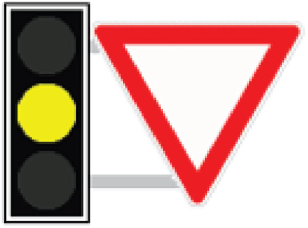
Figure 8 Traffic sign attached to traffic signal (Germany)
There are two basic types of light used in traffic signals worldwide: round and arrow-shaped. The colors are green, yellow, and red. The conditions for the round type are “on,” “off,” and “flashing.” The various combinations of light type, light color, condition, and traffic sign have different meanings that may also differ between countries. Despite the variety, the meanings of these combinations are generally related to permission or prohibition of a vehicle proceeding or to taking caution.
Table 1 describes the four-layer traffic rules model, and Figure 8 illustrates how we can ascertain a real traffic rule from a real object. Each combination of elements is assigned a traffic rule. For example, the combination of a red light and a green arrow is assigned a rule stating that a vehicle is permitted to turn right as a general rule. For the case shown in Figure 9, there is a “No Turn on Red” sign at the intersection. We assign this “No Turn on Red” sign a rule stating that a vehicle is prohibited from turning right as a general rule. We create a real traffic rule by combining these two general rules and considering the priority of each general rule.
Table 1 Traffic rules model
| Layer Name | Function |
| Real rule layer | Create real rules by combining general rules |
| General rule\newline layer | Assign traffic rules to various combinations of elements |
| Significant object layer | Combine objects that have significant rules |
| Real object layer | Decompose traffic signals or traffic signs into elements (objects) such as light type, color, and condition |
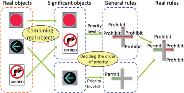
Figure 9 Illustration of defining real traffic rules from real objects
4.3 Plotting Objects in the Virtual World
Remarkable progress has also been made in GNSSs. In addition to the American Global Positioning System, we now have Russia's GLONASS, the EU's Galileo, and Japan's quasi-zenith satellite system, “Michibiki.” In the near future, measurement accuracies of less than 1 m will be available to general users [22–24]. The next generation mobile terminal and vehicle navigation system will then be able to determine their position within 1 m.
Every object logged in a CPTW keeps a session with the CPTW cloud servers and sends them positioning data. In addition, vehicles and pedestrians who drive and walk in a CPTW should have realistic aliases and avatars. For instance, an avatar should look like its user for ease of recognition.
Vehicles sometimes drive so fast that positioning data periodically sent from them would yield plotted positions different from their real ones. Here, we propose that a vehicle sends, in addition to its position, time stamps and three-dimensional data on its acceleration, and velocity. This information would enable the next generation mobile terminal or navigation system to estimate the relative positions of nearby vehicles in real-time, even though measurement accuracy is more than 1 m . We would re-plot every real vehicle in a way that it maintains its driving lane. In addition, the vehicle would detect the shapes of obstacles, the distance between them and itself, and send the detected shapes and distances to the CPTW servers.
Every traffic signal in the CPTW has to be synchronized with the real ones. A set-top box on a traffic signal would be a good way to detect a signal change. However, this method is impossible at present. Another idea is to store its change periods, and synchronize them with the mobility of vehicles and pedestrians near the traffic signal. Further study is needed to determine whether this idea is useful or not.
5 Communication Schemes
As we mentioned in the introduction, the CPTW needs the following communication modes:
- One-to-one mode: a real/virtual vehicle, driver or pedestrian communicates with another real/virtual vehicle, driver or pedestrian by pointing to their avatars or saying its relative position or nearby feature. This communication mode would be used for general communications. In particular, the CPTW system could use it to gather information such as additional positioning data or fuel consumption data from the vehicle navigation system and/or next generation mobile terminal.
- Group mode: multiple real/virtual drivers and pedestrians talk to each other. The originating object does not change, but people are free to join or leave a group. This communication mode would be used for talking with other real/virtual drivers and pedestrians.
- Relay mode: a real vehicle exchanges information with vehicles ahead of and behind it. This communication mode would be used for tandem driving to cut wind resistance and reduce fuel consumption. Virtual vehicles would not be included in such a line of vehicles.
The CPTW requires the high-speed constant Internet connection characteristics to plot vehicles or pedestrians precisely and the last two functions of the CPTW written in Section 3 also requires very low-latency and high reliability transmission characteristics.
Conventional cellular mobile networks do not as yet have above group mode or relay mode (they have the one-to-one mode). And their transmission characteristics are not sufficient for warning or avoiding traffic accidents. Trunked radio systems support group communications [25]. Unfortunately, the members of each group in a trunked radio system are fixed and cannot be changed freely. In addition, virtual drivers and pedestrians are not distinguished from real drivers in a communication group. Meanwhile, neither cellular mobile networks nor trunked radio systems support a relay mode. However, there are many studies on incorporating mobile networks in ITSs and for inter-vehicle communications in the real world [26]. ITU collaborates with organizations related to ITS to standardize its communications [27]. Some of their studies and standards are related to the above group mode and relay mode.
We propose the virtual communication modes shown in Figure 10. We will assume that every object in the CPTW keeps a session with the CPTW server as in Skype. In one–to-one mode, a real/virtual driver points to an avatar on a screen or says the features or relative position of a destination. Then he or she selects talking or messaging, and both the sessions of the driver and the indicated avatar or object are connected through the CPTW system. Avatars engaged in a conversation would change some aspect of their appearance, such as their color. When the other real/virtual drivers and pedestrians point to a central avatar, their sessions would all be connected and a communication group would be formed; this is the group mode. In the case of relay mode, a driver selects a form of usage such as tandem driving, and control signals are relayed within the line of real vehicles through the CPTW system. However, the positions of the vehicles cannot always be guaranteed to be the same as the real ones. Thus, their group mode and relay mode has difficulty in warning about the traffic accident just happened to the next vehicle coming if it's already within 20 to 30 meters from the accident site. For this reason, we hope that the 5G mobile networks of the future will shorten the transmission latency and provide the flexible group communication mode and relay mode.
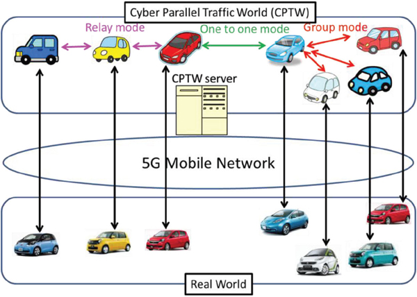
Figure 10 Communication modes in the CPTW
6 Development Scheme
Our aim is to provide a standardized CPTW for use by people worldwide, in both developed and developing countries, at little or no cost and enable them to create a CPTW representing their area of residence. Therefore, the system cost should be as low as possible. This means that expensive traffic facilities such as UTMS ones must be excluded and that most of the information needed must be gathered through the next generation mobile terminals and vehicle-mounted devices cooperating with residents in the world. CPTW is targeted for resident participation design, meaning that local residents construct the parts of CPTW in which they live. This will reduce the cost and make CPTW more realistic.
Since many issues including problems caused by communication networks described in Section 5 need to be resolved, it is very difficult for us to develop CPTW by ourselves.
We need many people and the ITU-T to help us. The best approach is thus to use open sources and an open standard scheme.
The issues to be addressed include
- deciding the specifications that include services;
- Service content,
- Protocol between client devices and the CPTW servers,
- Protocol between in-vehicle devices and others,
- Synchronization scheme between vertical traffic signals and real traffic signals, -etc.,
- deciding how to verify the developed technologies, software, and equipment to ensure they meet the specifications, and
- deciding how to provide the service and manage its operation.
7 Conclusion
In the proposed cyber parallel traffic world (CPTW) cloud service, roads, sidewalks, and traffic facilities such as traffic signals are presented as they are in the real world. Vehicles, pedestrians, and temporary obstacles move in synchronization with their real-world movements. Since the next generation mobile terminals will soon be able to determine their positions to accuracy within 1 m and most vehicles will be able to detect not only their own position but also the positions of other vehicles and obstacles, it should be possible to gather most of the information needed through the next generation mobile terminals and vehicle-mounted devices. The virtual structures would be constructed by extracting road data from maps and by gathering traffic rules for each country, storing the data in a roads database and a rules database, and using an application program to create 2D/3D roads using data in the roads database. This will make it possible to provide many useful and attractive services at a reasonable cost. In this paper, we also discussed how to realize the one-to-one communication mode, the group communication mode, and the relay communication mode of the CPTW system. Although business models for the CPTW were not discussed in this paper, since the CTPW connects the real world and the virtual world, it suits the O2O (Online to Offline) service well, and we can expect the creation of new business models.
References
[1] Erico Guizzo, “How Google's Self-Driving Car Works,” IEEE Spectrum, February 26, 2013.
[2] Autonomos Labs, http://www.autonomos.inf.fu-berlin.de/, October 2014.
[3] ITS GREEN SAFETY SHOWCASE, http://www.its-jp.org/english/its-green-safety-showcase/, October 2014.
[4] UTMS Society of Japan, http://www.utms.or.jp/english/index.html, October 2014.
[5] T. Oda, K. Takeuchi, Y. Yoshio, S. Niikura, “Evaluation of measured travel time utilizing two-way communication in UTMS,” IEEE, VNIS ' 96 (Volume: 7), pp. 54 – 61, Oct. 1996.
[6] TOYOTA SMART MOBILITY SOCIETY, http://www.toyota-global .com/innovation/smart_mobility_society, October 2014.
[7] Yoshitoshi Murata, Shinya Saito, “Proposal of “Cyber Parallel Traffic World” Cloud Service”, ITU Kaleidoscope 2014, S1.4. 2014.
[8] Chonggang Wang, etc., “Internet of Things,” IEEE, 2014
[9] Internet of Things Global Standards Initiative, http://www.itu.int/en/ITU-T/gsi/iot/Pages/default.aspx
[10] G. Araniti, C. Campolo, M. Condoluci, A. Iera, and A. Molinaro, “LTE for vehicular networking: a survey”, IEEE Communications Magazine, Vol. 51, No. 5, pp. 148–157, May 2013.
[11] Forum8, engineering 3D environment, http://www.forum8.com/default .asp, October 2014.
[12] Shinya Saito, Yoshitoshi Murata, Tsuyoshi Takayama and Nobuyoshi Sato, “An International Driving Simulator - Recognizing the Sense of a Car Body by the Simulator -,” Workshops in AINA 2012, W-FINA-S12.1, pp. 254–260, March 2012.
[13] OpenGL – The Industry Standard for High Performance Graphics, http://www.opengl.org/, October 2014.
[14] Simple DirectMedia Layer, http://www.libsdl.org/, October 2014.
[15] Home – OpenAL, http://openal-soft.org/, October 2014.
[16] CIE, CIE S 006.1/E-1998, “Road Traffic Lights - Photometric Properties of 200 mm Roundel Signals”, http://www.cie.co.at/Publications/index. php?i_ca_id=467, October 2014.
[17] ISO, ISO 16508:1999,” Road traffic lights – Photometric properties of 200 mm roundel signals”, http://www.iso.org/iso/home/store/catalogue_tc/catalogue_detail.htm?csnumber=31003, October 2014.
[18] California Driver Handbook - Traffic Lights and Signs, http://apps.dmv.ca. gov/pubs/hdbk/traff_lgts_sgns.htm, October 2014.
[19] Florida Drivers Handbook - Traffic Signals, http://www.123driving.com/ flhandbook/flhb-traffic-signals.shtml, October 2014.
[20] Driver Handbook in New York, http://www.dmv.org/ny-new-york/driver-handbook.php\#Drivers-Manual, October 2014.
[21] How to Germany – Driving in Germany -, http://www.howtogermany.com /pages/driving.html, October 2014.
[22] Groves, Paul D, “Principles of GNSS, Inertial, and Multisensor Integrated Navigation Systems: Second Edition,” ISBN=9781608070053, Artech House Publishers, 2013 John
[23] M. Dow, R. E. Neilan, C. Rizos, “The International GNSS Service in a changing landscape of Global Navigation Satellite Systems,” Journal of Geodesy, Volume 83, Issue 3–4, pp. 191–198, March 2009.
[24] Y Li, C Rizos, “Evaluation of positioning accuracy of GNSS with QZSS augmentation,” IGNSS Symposium 2011, November 2011.
[25] Trunked Radio Communication System, http://wiki.radioreference.com/ index.php/Trunking, October 2014.
[26] Mihail L. Sichitiu, Maria Kihl, “Inter-Vehicle Communication System: A Survey,” IEEE Communication Surveys & Tutorials, 2nd Quarter, 2008.
[27] Collaboration on ITS Communication Standard, http://www.itu.int/en/ ITU-T/extcoop/cits/Pages/default.aspx
Biographies

Yoshitoshi Murata received his M.E from Nagoya University, Japan. He received his Ph.D from Shizuoka University, Japan. From 1979 to 2006, he was belonging to NTT and NTT DoCoMo and developing mobile communication systems, mobile terminals and services. Since 2006, he is a professor of faculty of Software and Information Science, Iwate Prefectural University. Prof. Murata was awarded the best paper of the ITU-T “Innovations in NGN” Kaleidoscope Academic Conference 2008. His research interests include mobile communication, sensor usage application and ITS. He is a member of IEEE, IEICE and IPSJ.

Shinya Saito received his M.E. from Iwate Prefectural University. Since 2013, he is belonging to Information System Dept. in Tokyo Electron Limited and involved in the work of ERP system and Business Intelligence.
Journal of ICT, Vol. 2, 65–86.
doi: 10.13052/jicts2245-800X.221
© 2014 River Publishers. All rights reserved.