LoRaWAN Link Layer
Olivier Seller
Technical Fellow, Semtech, and LoRa Alliance® Technical Committee Vice-Chair, Fremont, CA, United States
E-mail: oseller@semtech.com
Received 30 November 2019; Accepted 16 December 2020; Publication 30 April 2021
Abstract
The LoRaWAN Link Layer specification [1] is a communication protocol for the Internet of Things. It targets low power, long range, low cost communication using unlicensed spectrum. Network topology is collaborative, which reduces a lot protocol signalling compared to a cellular network. The device is connected to a network server, and protocol overhead is limited to 13 bytes for any data frame. There are three classes of operation. Class A is optimized for low power operation of end-devices, while class B and class C offer reduced downlink latency. The protocol specification offers several mechanisms to adjust the link layer parameters: adaptive data rate, adaptive power control, variable repetition rate, and channel selection.
Keywords: LoRaWAN protocol, medium access control, link layer, network server, adaptive data rate.
1 Introduction
The LoRaWAN Link Layer specification [1] is a communication protocol for the Internet of Things. The specification covers medium access control, link layer, and network layer. It targets low power, long range, low cost communications using unlicensed spectrum. Many applications in the Internet of Things are for devices that are battery operated, and that have small amount of information to transmit: this is uncommon in the field of wireless communications, and deserves specific optimization. Low power and low cost operation are very important to enable new IoT applications for machines or objects which still remain completely unconnected today. Energy efficiency is one of the main goals of the LoRaWAN protocol design, with a very low protocol overhead for sparse transmissions. Another goal is simplicity, to allow low cost implementations and certification. The architecture of a LoRaWAN network is shown on Figure 1 below.
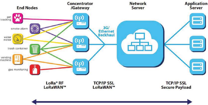
Figure 1 LoRaWAN network architecture.
LoRaWAN networks have a star-of-stars topology in which gateways relay packets between end-devices and a central network server. The network server, in turn, routes packets received by gateways to an associated application server and vice versa. Communication is generally bi-directional, although uplink communication from an end-device to the network server and application server is the predominant traffic. The LoRaWAN Link Layer specification [1] describes communication between an end-device and a network server. The application layer is served directly by LoRaWAN Link Layer.
2 Access Network Topology
LoRaWAN networks offer nationwide coverage, like traditional cellular networks do, but there is a very important difference in network topology. Figure 2 below shows this difference between cellular network and LoRaWAN collaborative network.
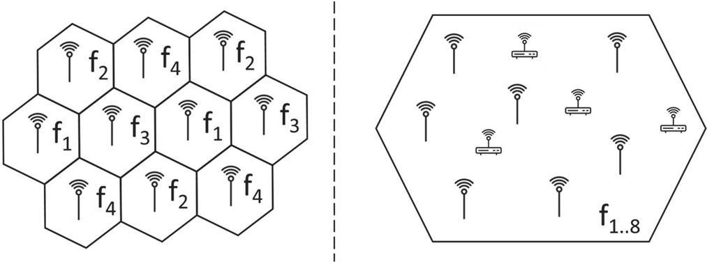
Figure 2 Cellular (left) vs LoRaWAN collaborative (right) network topologies.
In a cellular network, the basic network unit is a cell, usually served by a base-station. The cellular device is connected to a base-station, if it changes cell it has to connect actively to another base-station, and change its frequency of operation. A LoRaWAN network does not define cells, and gateways are transparent to the LoRaWAN end-device. The end-device is connected to a network server, through one or many gateways that use the same set of frequencies. Uplinks can be received by multiple gateways, there is no fixed association between end-devices and gateways. Consequently, the LoRaWAN end-device does not need to connect to a given gateway: this saves a lot of protocol signalling. Nomadic devices might transmit information only a few times a day, and each time from a different place: in this situation, cellular networks require cell handover procedures and explicit signalling before transmitting useful information, which may lead to more signalling traffic than application data. Thanks to the collaborative topology, a LoRaWAN end-device, once connected to the network, stays connected as long as it is regularly within coverage.
There are many other advantages and considerations associated with this network topology. First, macro diversity is embedded in the network, as all gateways collaborate to the demodulation of uplink packets. This naturally increases coverage and quality of service for hard to reach end-devices, and on the downlink this greatly simplifies multicast. Second, LoRaWAN targets unlicensed bands. In an unlicensed band, no one owns the band, and each user should limit its interference to other users. Therefore, it is not possible to define cells, allocate them frequencies, and load them to their maximum radio capacity: this would not be a fair spectrum usage in an unlicensed band. Third, radio planning is easier, as different kind of gateways, indoor or outdoor, are added seamlessly. Last but not least, since all gateways listen to the same channels, end-device positioning through triangulation is possible from a single uplink, using either RSSI or TDOA.
3 Packet Format
Figure 3 shows the format of a LoRaWAN data frame. The frame payload may be empty, and then the frame port field is not present either. The length of the frame payload is determined by the physical layer. The maximum payload size may be lower than 242 bytes for some data rates. This is specified in the regional parameters specification [3], for the applicable LoRa data rates, and FSK data rates.
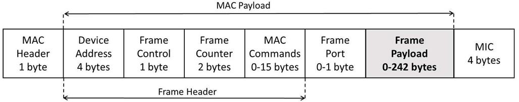
Figure 3 Data frame format.
The MAC header signals the frame type and protocol major version. Frame types can only be uplink data, downlink data, join request, or join response. Join request and join responses frames are used for end-device activation. Once an end-device is connected to a network server, only data frames are exchanged. For data frames, MAC header also signals whether an acknowledgement is required.
The MIC field is present for security; it ensures authentication of the frame by the receiver. It is computed using AES-128 and session keys derived during activation. Thanks to the presence of a frame counter, which is 4 bytes but of which only the two least significant bytes are sent, replay attacks are prevented.
The device address uniquely identifies an end-device on a given LoRaWAN network. Device address has a variable length prefix, that prefix also identifies the network server. This is useful for passive roaming, where network servers exchange frames from their respective end-devices and recognize each other’s’ traffic based on the prefix field.
Frame Control signals acknowledgement, adaptive data rate status, and the length of the piggybacked MAC commands. It also signals in each downlink frame whether further traffic is pending for this particular end-device, and on uplink frames it signals whether Class B is enabled.
MAC commands are optional and carried in a dedicated field with variable size from 0 to 15 bytes. MAC commands themselves have a variable length.
Frame payload is the application data, it is exchanged between an application server and an end-device. Frame payload is encrypted using AES-128, with a symmetric session key that only the end-device and application server know. This way, the network server cannot decrypt the application data, and end-to-end security is present between application server and end-device.
Instead of sending application data, the frame payload field can be a list of MAC commands. Then the Frame Port value is set to zero, and a different encryption key is used between the end-device and the network server.
Overall, the protocol overhead on each data frame is only 13 bytes. So when asked the question: “how many bytes do you need, so as to transmit 32 useful information bytes?” the answer is “only bytes.” This is true even if the LoRaWAN end-device transmits only once a day, and even when it is moving. This predictability simplifies the design of LoRaWAN applications. In [2], table IV, one can see that for Nb-IoT the protocol overhead is such that power consumption of a device hardly depends on the application traffic this device generates. With LoRaWAN, a lower signalling overhead, both in terms of number of messages, and protocol overhead in each message, translates directly into a longer battery lifetime.
4 Classes of Operation
There are three classes of operation, all of which offer bi-directional communication. Whatever the class, the uplinks are always initiated by end-devices in an ALOHA manner, i.e. at a random time, on a random channel selected among the available channels. The transmission slot scheduled by the end-device is based on its own communication needs with a small variation based on a random time basis.
Class A is common to all end-devices. When an end-device enables Class B, it also complies with Class A. When an end-device enables Class C, it also complies with Class A. Class B and Class C are exclusive. Each class of operation defines the downlink opportunities. Class B and class C enable deterministic downlink latency to the end-device. Class C offer more downlink opportunities than Class B, which in turn offers more than Class A.
4.1 Class A for All End-devices
Class A offers the lowest power consumption. After each uplink transmission, the end-device opens two short reception windows at deterministic times and frequencies. Assuming the transmitted power is 14 dBm, the power consumption associated with the two receive windows is typically 5% of the transmit power consumption. This is why Class A offers low power consumption. There is no power overhead for uplink since no signalling is required before transmission and very little power overhead for downlink. The majority of current consumption comes from the data uplink transmissions. This Class A operation is best suited for applications that require only downlink communication from the network server shortly after the device has sent an uplink transmission; downlink communications from the network server at any other time must wait until the next end-device uplink. Network server can signal in each downlink frame that pending traffic is available for the end-device. This will lead the end-device to send the next uplink faster so as to receive the pending downlink, hence reducing the downlink delay.
Figure 4 shows the timing of Class A transmission of the two downlink opportunities RX1 and RX2.
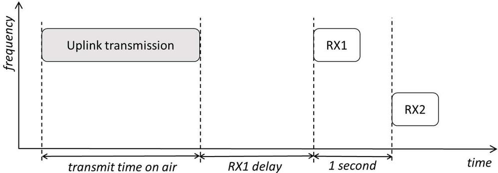
Figure 4 Class A end-device receive slot timing.
All physical layer parameters are region-specific and are defined in [3]. For regions which follow ETSI regulations, for instance in Europe with frequencies between 863 MHz and 870 MHz, the RX1 window uses the same channel as the uplink. For regions which follow the FCC regulation, for instance in the USA with frequencies from 902 MHz to 928 MHz, the RX1 window uses a channel which is a deterministic function of the uplink channel index. For all regions, the RX2 window uses a fixed channel, and a fixed data rate.
4.2 Class B-enabled End-devices
A class B-enabled device opens additional receive windows at scheduled times and channels, using a determined data rate. When one of these receive windows collide with one of the random class A receive windows, the device opens its receive window according to the latter as that one has priority.
In order for the device to open these receive windows at the scheduled times, it receives a time-synchronized beacon from the gateways. Gateways thus require accurate time synchronization, which is usually achieved with a GPS. The beacon period is set to 128 seconds; the start of each period is a multiple of 128 seconds since the start of GPS epoch (January 6th, 1980, 00:00:00 UTC, no leap second). Within each beacon period, 4096 time slots are defined, in addition to a 5 seconds window for beacons transmission and reception. A Class-B enabled end-device listens to regularly spaced slots during each period. The number of open slots is signalled to the network server by the end-device, it can have the following values: 1, 2, 4, 8, 16, 32, 64 or 128. The downlink latency in class B ranges from 128 seconds down to 6 seconds. At each beacon period, the time offset of the first opened slot is randomized, to prevent repeated collisions between two end-devices.
Class B is well suited to multicast. Once a multicast address is set, with its associated security keys, the associated end-devices listen to the corresponding class B ping slots. These slots come in addition to each device Class A receive windows, and to their unicast Class B ping slots.
4.3 Class C-enabled End-devices
Enabling class C allows end-devices to listen almost continuously to potential downlinks. These are bi-directional devices with maximum amount of receive slots. The reception on the Class C channel only stops during transmission, and to listen to the following Class A receive windows. Class C end-devices will use more power to operate than Class A or Class B end-devices, but they feature the lowest latency for downlink communication. Usually, these devices are mains-powered, but it is possible to enable temporarily Class C, for instance for firmware upgrade over the air.
5 Link Adaptation
The LoRaWAN link layer specification defines several mechanisms to adapt the physical layer parameters. These adaptation mechanisms help optimizing the end-device power consumption and network capacity.
5.1 Adaptive Data Rate
When an end-device is nomadic or static, it signals to the network server, in each uplink frame, that it can control its uplink data rate. The goal of this optimization is to maintain connectivity while using the smallest time on air possible. The available data rates are region-specific. See the Table 1 given for an application payload of 20 bytes and based on the ETSI regions. Sensitivity corresponds to commercial carrier-grade gateways.
Table 1 Data rates characteristics for ETSI regions
| DR0 | DR1 | DR2 | DR3 | DR4 | DR5 | |
| data rate | 240 bps | 440 bps | 980 bps | 1.8 Kbps | 3.1 Kbps | 5.5 Kbps |
| Time on air | 1810 ms | 987 ms | 453 ms | 247 ms | 134 ms | 72 ms |
| Sensitivity | 142 dBm | 139 dBm | 137 dBm | 134 dBm | 131 dBm | 129 dBm |
| SINR | 22 dB | 19 dB | 17 dB | 14 dB | 11 dB | 9 dB |
The fall-back mechanism is suited to fit non-systematic downlinks. When an end-device has not received any downlink after a given number of uplinks, it can be because the network server has no data nor MAC commands to send, or because the connection is lost due to a too high data rate. Then, this end-device will set a flag in the frame control field of its uplink frames to request a downlink. The end-device will wait for several uplinks without network server response before lowering its data rate, to give the network server several opportunities of downlink.
When the maximum data rate is reached, adaptive power control is used to limit interference to other end-devices, and other systems. This also extends battery life. The same MAC command controls both the data rate and the transmit power.
The LoRaWAN data rates have the property that different data rates can be received simultaneously, on the same channel by the gateways. This is because required SNR for each data rate is lower than 0 dB, and because different data rates interfere to each other more or less like gaussian noise. This property is often called data rates orthogonality, though this is not a strict orthogonality. It is possible to compute orthogonality matrices by observing the statistics of the received signal levels, for each data rate. An example of such an orthogonality matrix is shown on Table 2. This example corresponds to a power control range of 15 dB. The orthogonality matrix is defined as the probability that a time overlap of two frames results in a collision, which is the loss of the victim frame. With power control, the column corresponding to the maximum data rate as aggressor shows lower probabilities.
Table 2 Orthogonality matrix example
| DR0 | DR1 | DR2 | DR3 | DR4 | DR5 | |
| DR0 victim | 64% | 0% | 0% | 2% | 6% | 19% |
| DR1 victim | 0% | 81% | 0% | 2% | 6% | 18% |
| DR2 victim | 0% | 0% | 80% | 2% | 6% | 18% |
| DR3 victim | 0% | 0% | 0% | 80% | 6% | 17% |
| DR4 victim | 0% | 0% | 0% | 1% | 80% | 17% |
| DR5 victim | 0% | 0% | 0% | 1% | 5% | 76% |
In the table above, one can read for instance that in this network, on average, when a DR4 frame overlaps a DR5 frame, that DR5 frame has a 5% probability of not being correctly received on one gateway. The diagonal terms are higher because of the same data rate, where interference is not noise-like. We also see that with proper adaptive data rate and power control, the lowest data rates DR0, DR1, and DR2, which have the longest frames, are so low in power that they do not impact at all the reception of other data rates.
5.2 Systematic Retransmissions
Another link adaptation parameter is the number of systematic retransmissions an end-device should perform for each uplink. Retransmissions are systematic, but as soon as the end-device receives a Class A downlink, the frame is not repeated. The successive uplinks use random channels, so frequency diversity is present. The channel plans in ETSI regulated regions have 8 to 16 channels; in FCC regulated regions 64 uplink channels are used.
Figure 5 shows that systematic repetition is a valid strategy to increase transmission success rate for a given time on air budget. This is true even when the channel variations are small, for instance when the end-device is static and not in line of sight of the gateway. Such an end-device, thanks to frequency diversity, will benefit from Rayleigh fading diversity.
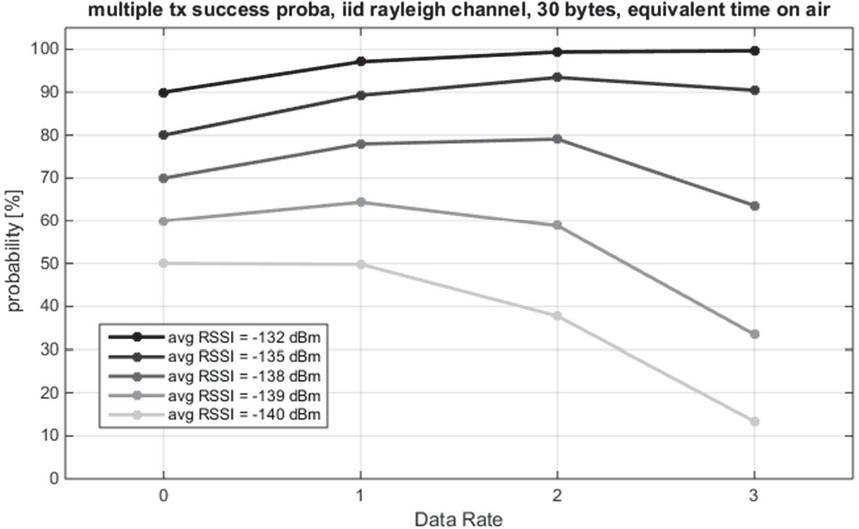
Figure 5 Reception success probability with repetitions, 30 application bytes frames.
We see that as soon as success probability is above 60% for single frame transmission, it is a good strategy to use a higher data rate and repeat the frame. For the Rayleigh fading channel, which corresponds to static devices with very stable propagation conditions, the optimum repetition rate is 4 when targeting success rate of 80% or higher. When the propagation channel exhibits more variations, then it is better to use a higher repetition rate along with a higher data rate.
5.3 Operating Channels
A LoRaWAN network server can adapt dynamically the operating channels used by an end-device. Channels may be created, or enabled, either upon activation of the end-device, or during the operations of the end-device. This is an important part of network optimisation, here are some examples:
• Network operators may use common channels to ease roaming between them.
• Network operators may also use dedicated channels to optimize overall network capacity or separate traffic.
• Some areas may suffer from interference, then corresponding channels may be masked in the channel plans of fixed devices of this area.
• To optimize quality of service for some end-devices, some channels may be reserved to these end-devices.
• It is possible to limit the usable data rates on a per channel basis for all end-devices, which is for instance a way to reserve some channels for hard to reach end-devices, or to reserve some channels for high data rates.
Depending on the region, and depending on the RF characteristics of the device, there may be an asymmetry in link budget between uplink and downlink packets. To accommodate this, the network server can adjust a data rate index offset between uplink and downlink. It is also possible to define a different channel correspondence between uplink and downlink.
6 Conclusion
The LoRaWAN Link Layer specification is a communication protocol for the Internet of Things. It targets low power, long range, low cost communications using unlicensed spectrum. Network topology is collaborative, which significantly reduces the protocol signalling overhead compared to cellular technologies. The device is connected to a network server, and protocol overhead is limited to 13 bytes for any data frame. There are three classes of operation. Class A is optimized for low power operation of end-devices, while class B and class C offer lower downlink latency. The specification offers several mechanisms to adjust the link layer parameters: adaptive data rate, adaptive power control, variable repetition rate, and channel selection.
References
[1] TS001-1.0.4, LoRaWAN Link Layer Specification, LoRa Alliance Technical Committee, October 2020
[2] B. Martinez, F. Adelantado, A. Bartoli, X. Vilajosana, ‘Exploring the Performance Boundaries of NB-IoT’, IEEE Internet of Things Journal, Volume 6, Issue 3, June 2019.
[3] RP002-1.0.2 LoRaWAN Regional Parameters, LoRa Alliance Technical Committee, November 2020
Biography

Olivier Seller is technical fellow at Semtech, and vice-chair of LoRa Alliance Technical Committee. He is the editor of the LoRaWAN link layer specification since 2019. He is co-inventor of the LoRa technology, and co-founder of Cycleo that developed LoRa initially, his focus was the LoRa modulation and implementation of receivers. Upon acquisition of Cycleo by Semtech in 2012, Olivier architected the LoRa localisation solution, designed the “find my stuff” radio capability of LoRa chips, and co-designed the LR-FHSS modulation.
Olivier studied in Ecole Polytechnique and Telecom Paris, then worked in the telecom and semiconductor industries with experiences in an 802.16 start-up, in Orange Labs, and in Cambridge Silicon Radio.
Journal of ICT, Vol. 9_1, 1–12. River Publishers
doi: 10.13052/jicts2245-800X.911
This is an Open Access publication. © 2021 the Author(s). All rights reserved.