LoRa-Alliance Regional Parameters Overview
Dave Kjendal
CTO, Senet Inc. and LoRa Alliance® Regional Parameters Working Group Chair, Fremont, CA, United States
E-mail: dkjendal@senetco.com
Received 29 December 2019; Accepted 17 December 2020; Publication 30 April 2021
Abstract
The LoRaWAN Regional Parameters specification defines the adaptation of the LoRaWAN Link Layer specification to comply with the various regulations enforced throughout the world on the use of various frequency bands of unlicensed spectrum which are available. It defines default values for Link Layer parameters and channel plans. Each of the regional channel plans can be broadly characterized as dynamic channel plans, with a small number of default channels, or fixed channel plans, where all channels are defined then selectively activated by the network. Regional parameters are defined for a vast majority of countries in the world, using 9 main channel plans, and support for additional countries is regularly added.
Keywords: LoRaWAN, regional parameters, unlicensed spectrum, regulation, regulatory approval.
1 Introduction
This document will attempt to provide the reader with a brief overview of the LoRaWAN Regional Parameters specification and its application to implementations of LoRaWAN around the world.
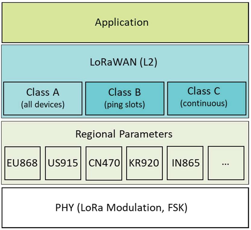
Figure 1 Relationship of layer 2 and regional parameters specifications.
The LoRaWAN Regional Parameters specification [1] is a companion document to the LoRaWAN Link Layer specification, both of which are maintained by the Technical Committee of the LoRa Alliance. While the LoRaWAN Link Layer specification [2] defines the air interface between a compliant end-device (sensor, actuator, tracker, etc.) and a compliant network core, the LoRaWAN Regional Parameters specification defines the adaptation of the LoRaWAN Link Layer specification to comply with the various regulations enforced throughout the world on the use of various frequency bands of unlicensed spectrum which are available. These regulations are defined for example in the documents referenced in footnotes [3–5]. For convenience, a quick cross reference table is included in the LoRaWAN Regional Parameters specification to help implementers identify the relevant frequency bands and LoRaWAN channel plans which are available, by country.
One of the primary goals of the LoRa Alliance Regional Parameters Working Group, which maintains the specification, is to create the smallest number of regional channel plans which cover the largest possible number of regulatory regions. In doing so, the group minimizes the complexity to implementers as well as the certification cost, as end-device certification is enumerated by Link Layer revision and Regional Parameters revision and channel plan.
Prior to version 1.0.2 of the LoRaWAN Link Layer specification, the information contained with the LoRaWAN Regional Parameters specification was included directly within the body of the LoRaWAN Link Layer specification. However, as both new regional channel plans and the country-based application of these channel plans can occur frequently, the two documents are now independently maintained and published. Starting with version RP002-1.0.0, the LoRaWAN Regional Parameters specification applies to all published versions of the LoRaWAN Link Layer specification.
In addition, the LoRaWAN Regional Parameters specification documents the physical layer configurations required for compliant operation of LoRaWAN Link Layer radios using various radio frequency modulation techniques.
2 LoRaWAN Link Layer Default Values
The LoRaWAN Link Layer specification defines the use of many different variables (which may be modified through MAC Commands) and constants. The LoRaWAN Regional Parameters specification provides the recommended global default values for these variables and constants, and rarely, when appropriate, the region-specific recommended overrides to any specific variable or constant.
These include:
• Receiver configurations
RECEIVE_DELAY1 – defines when the end-device opens its first Class A receive window (RX1)
RECEIVE_DELAY2 – defines when the end-device opens its second Class A receive window (RX2)
JOIN_ACCEPT_DELAY1 – defines when the end-device opens its first receive window after sending a Join-Request
JOIN_ACCEPT_DELAY2 – defines when the end-device opens its second receive window after sending a Join-Request
RX1DROffset – the index into the RX1DROffset table to find the data rate to be used by the end-device when opening its first Class A receive window
DownlinkDwellTime – a Boolean value indicating to the end-device if the network will be constrained to dwell time limitations when sending downlinks; this impacts the data rate of the Class A downlinks and maximum payload size of both Class A and Class B and Class C downlinks
• Transmit configurations
RETRANSMIT_TIMEOUT – the minimum time period which must elapse before an end-device retransmits a frame
UplinkDwellTime – a Boolean value indicating that the end-device is constrained to dwell time limitations when sending uplinks
• ADR Backoff
ADR_ACK_LIMIT – the number of uplinks sent without receiving any downlinks after which the end-device will set ADRACKRequest in all subsequent uplinks
ADR_ACK_DELAY – the number of additional uplinks the end-device will send, after ADR_ACK_LIMIT has been reached, before it will initiate the next ADR back-off step
• Class B configurations
PING_SLOT_PERIODICITY – the periodicity at which the end-device will open its Class B receive window, when operating as Class B enabled
PING_SLOT_DATARATE – the data rate at which the end-device will open its Class B receive window, when operating as Class B enabled
PING_SLOT_CHANNEL – the channel at which the end-device will open its Class B receive window, when operating as Class B enabled
3 Regional Channel Plan Architectures
All regional channel plans follow similar design and description to aid the developer who may be implementing solutions for multiple countries and regions around the globe. All plans contain the details required to adapt the LoRaWAN Link Layer specification to each region, this includes defining the following:
• Default and Join Channels required to be supported within the region
• The Data Rates (an index which defines both the channel bandwidth, spreading factor and modulation) defined within the region
• Both the maximum transmit power as well as the adaption of the LinkADRReq MAC Command information which modifies the transmit power being requested of the device from the network
• The Maximum Payload Size, which typically varies by data rate in order to comply with regulatory constraints
• The interpretation of both the Channel Frequency List (CFList) and the Channel Masks in the LinkADRReq MAC Command
• The end-device receiver configuration, specifically the data rate to be used by the receiver
• Class B configurations required for acquisition of the beacon, ping-slot timing and receive frequency and data rate
Each of the regional channel plans can be broadly characterized in to one of two types of plan: dynamic channel plans (modelled after the original EU868 plan) and fixed channel plans (modelled after the original US915 plan).
3.1 Dynamic Channel Plans
Dynamic channel plans are characterized by the fact that a small number of default and join channels are rigidly specified while all other channels (up to the current maximum of 16 total channels, including the default channels) are dynamically defined by the network at arbitrary frequencies within the band. These dynamic channels may be provisioned as the devices join the network, through the CFList (which, for dynamic plans, specifies a list of channel frequencies to be created) included in the Join-Accept frame, or created, deleted or modified during normal operation through MAC commands issued by the network. Additionally, by default, uplink and downlink channels are overlapping (uplink channel 1 is the same frequency as downlink channel 1) and the end device opens its RX1 windows on the same channel as the uplink.
3.2 Fixed Channel Plans
Fixed channel plans are typically defined in regions with large amounts of spectrum available for unlicensed use. In these plans, a relatively large number of channels are defined at fixed frequencies throughout the band. All channels are considered default channels, but not all networks are listening to all channels. As a result, end-devices will attempt the join process using all possible channels. Upon successful join, the network will provision the active set of channels, from within the list of all possible channels, for the device using the CFList (as part of the Join-Accept frame) or through MAC commands during normal operation. For fixed channel plan regions, channels are never created, modified or deleted, simply masked in and out of current operation. In many fixed channel plan regions, there are fewer downlink channels than uplink channels, in which case the modulus of the uplink channel (by the number of downlink channels) is typically used to calculate the correct RX1 receive frequency.
4 Dynamic Channel Plans – Regional Details
4.1 EU868-870
The original dynamic channel plan, EU868 defines three default channels and eight data rates. Typical maximum transmit power is 16 dBm EIRP (14 dBm ERP). Default Class B operation for both the beacon and the ping-slot is 869.625 MHz, which is not overlapping with the three default channels. End-devices must support the dynamic configuration of up to an additional 13 channels (for a total of 16 channels defined). Maximum application payload size varies from 51 to 242 bytes depending on data rate. Devices using this band are duty-cycle limited by regulation.
All of Europe and much of the Middle East and Africa support EU868.
4.2 EU433
EU433 is modelled directly on EU868 except for the band utilized and the fact that the typical maximum transmit power is +12dBm EIRP. EU433 has not been widely utilized to date due to its narrow available bandwidth and the fact that it is already widely utilized by other protocols. As a result, there are relatively few products available in the market using this channel plan.
4.3 IN865-867
IN865 is very similar to EU868, in a slightly different frequency band and with some notable restrictions removed. No dwell time or duty cycle limitations are imposed, and the maximum transmit power is 30 dBm.
Most of the Indian Subcontinent supports IN865.
4.4 KR920-923
The channel plan for South Korea also defines three default channels but only supports six data rates. Additionally, specific bands support different maximum transmit powers for the end-device: either 10 dBm or 14 dBm EIRP). Maximum application payload size varies from 51 to 242 bytes depending on data rate. Devices using this band are required to implement Listen-Before-Talk (LBT) which means that the transmitting device must first open its receiver and listen for the presence of other transmissions, if the channel is free, the device initiates its own transmission.
4.5 AS923
AS923 is the template for a series of regional channel plans that all use two default channels instead of the three defined in EU868, EU433 and IN865. Eight data rates and maximum application payloads which vary from 51 to 242 bytes are the same as those defined in EU868, however, some countries impose dwell time restrictions which are not required in EU868. For this reason, the join process does not use the two lowest data rates (which are not available in countries with the dwell time restriction). Devices support a default maximum transmit power of 16 dBm EIRP. By default, the Class B beacon and ping-slot are aligned with the second default channel at 923.4 MHz.
As of RP002-1.0.1 AS923 has been further defined into three sub-plans which are identical except for a frequency offset (which applies to all default frequency definitions). The first sub-plan, AS923-1, is identical to the original AS923 plan (frequency offset is zero). The second sub-plan, AS923-2, is offset by 1.8 MHz. The third sub-plan, AS923-3, is offset by 6.6 MHz.
Much of South East Asia and Oceania support AS923-1. Notably, AS923-2 supports Indonesia and Vietnam. AS923-3 supports much of Europe as well as Cuba and the Philippines.
4.6 RU864-870
RU864 also supports two default channels but is duty-cycle limited and has no LBT requirement. Eight data rates and maximum application payloads which vary from 51 to 242 bytes are the same as those defined in EU868. By default, the Class B beacon is aligned with the second default channel at 869.1 MHz and the ping-slot is aligned with the first default channel at 868.9 MHz.
4.7 CN779-787
The CN779-787 band is no longer available for new products or deployments and should be considered deprecated.
5 Fixed Channel Plans – Regional Details
5.1 US902-928
The original fixed channel plan region, US915 defines 64 125 kHz and 8 500 kHz uplink channels and 8 500 kHz downlink channels. All 125 kHz channels are restricted to a maximum 400 mSec dwell-time (time-on-air). This limits uplink application payload sizes to between 11 and 242 bytes depending on data rate. Downlink application payload sizes vary from 53 to 242 bytes depending on data rate. Uplink and downlink bands are separated by approximately 7 MHz of spectrum, which allows for the creation of full-duplex gateways. Many networks support only a subset of the uplink channels, but end-devices must use all channels by default, until configured (through the CFList or LinkADRReq command) to use a subset. Unlike the dynamic channel plan regions, by default, Class B Beacons and ping-slots hop through all eight downlink channels.
US915 is supported throughout North America (US, Canada and Mexico) and in several other countries in the Americas.
5.2 AU915-928
AU915 is very similar to US902, but executed in half the frequency range, resulting in the overlap of uplink and downlink channels. AU915 allows devices to operate in compliance with a dwell time limit or in the absence of such a limit. When regulators do not impose the dwell time limit, additional data rates (and additional application payload sizes) are available to the end-device.
AU915 is supported throughout Oceania and vast majority of Central and South America.
5.3 CN470-510
CN470 was recently completely rewritten based on the experience and with the assistance of Chinese LoRa Alliance member companies. It is broadly structured into two different style plans, one which requires an RF frontend capable of supporting 26 MHz of bandwidth, and one which only requires 20 MHz. These two styles are further broken down into two sub-plans (each). Finally, the two 20 MHz plans are further broken down into an additional eight (for sub-plan A) and two (for sub-plan B) plans.
Due to the recent reworking of this plan, it is considered experimental.
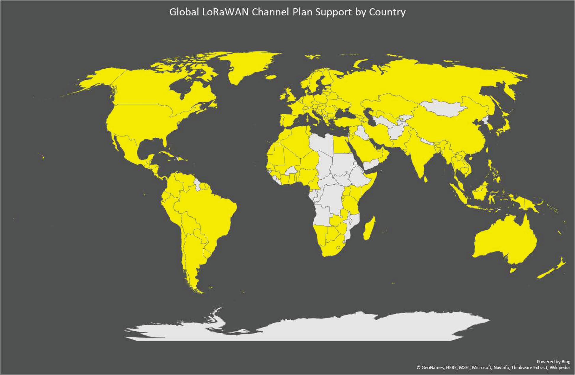
Figure 2 Regional Parameters worldwide coverage.
6 Conclusion and Future Work
Even with the vast majority of countries around the world able to implement LoRaWAN compliant solutions, several countries remain to be addressed due to challenges identifying appropriate unlicensed bands, confusing local regulation and difficulties contacting regulating authorities. The Regional Parameters Working Group and the Regulatory Working Group are actively collaborating with member companies and local regulators to address these gaps and provide complete definitions for LoRaWAN operation across the entire globe. Enhancements are currently being made to add support for additional countries in Asia and the Middle East and to take advantage of newly available spectrum throughout Europe.
The LoRa Alliance tracks to status of regional adaptation throughout the world. The map below on Figure 2 was generated as of RP002-1.0.2 in December 2020. Countries in yellow represent countries where member companies have documented to the LoRa Alliance that they have end-device which have received both LoRa Alliance certification as well as local regulatory type certification. Countries in blue represent the remainder of the countries for which the LoRa Alliance has defined an adaption of LoRaWAN through the LoRaWAN Regional Parameters specification. Countries in grey are those countries which the LoRa Alliance is still working with member companies and local regulators to identify the unlicensed bands available for LoRaWAN operation.
References
[1] TS001-1.0.4, LoRaWAN Link Layer Specification, LoRa Alliance Technical Committee, October 2020
[2] RP002-1.0.2 LoRaWAN Regional Parameters, LoRa Alliance Technical Committee, November 2020
[3] Code of Federal Regulations, Title 47, Part 15 https://www.gpo.gov/fdsys/pkg/CFR-2017-title47-vol1/pdf/CFR-2017-title47-vol1-part15.pdf
[4] ETSI EN 300 220-1 (V3.1.1) (02-2017): “Short Range Devices (SRD) operating in the frequency range 25 MHz to 1 000 MHz; Part 1: Technical characteristics and methods of measurement”.
[5] ETSI EN 300 220-2 (V3.1.1) (02-2017): “Part 2: Harmonized Standard covering the essential requirements of article 3.2 of Directive 2014/53/EU for non-specific radio equipment”.
Biography

Dave Kjendal is Chief Technology Officer & Chief Operating Officer at Senet, with responsibilities for research and design, product management and product marketing. A senior executive with over 18 years of experience in high-tech innovation management and complex product development, Dave is a successful leader of large multi-site teams that have delivered dozens of leading-edge LAN/WLAN product lines, embedded and application software designs as well as ODM and OEM development models. Prior to joining Senet, Kjendal held leadership positions with industry-related technology companies including Extreme Networks as Senior Vice President Engineering, Siemens Enterprise Communications as Senior Vice President, General Manager, and as Engineering Architect for Enterasys Networks. Kjendal received his Bachelor of Science in Physics from University of New Hampshire and Master of Science, Electrical Engineering from the University of South Alabama.
Journal of ICT, Vol. 9_1, 35–46. River Publishers
doi: 10.13052/jicts2245-800X.914
This is an Open Access publication. © 2021 the Author(s). All rights reserved.