IEEE 802.11ah: A Long Range 802.11 WLAN at Sub 1 GHz
Received 10 April 2013; Accepted 14 May 2013
Journal of ICT Standardization, Vol. 1, 1–25.
doi: 10.13052/jicts2245-800X.125
Copyright © 2013 River Publishers. All rights reserved.
Weiping Sun, Munhwan Choi and Sunghyun Choi
- Department of ECE and INMC, Seoul National University, Seoul, Korea; email:{weiping, mhchoi}@mwnl.snu.ac.kr, schoi@snu.ac.kr
Abstract
IEEE 802.11ah is an emerging Wireless LAN (WLAN) standard that defines a WLAN system operating at sub 1 GHz license-exempt bands. Thanks to the favorable propagation characteristics of the low frequency spectra, 802.11ah can provide much improved transmission range compared with the conventional 802.11 WLANs operating at 2.4 GHz and 5 GHz bands. 802.11ah can be used for various purposes including large scale sensor networks, extended range hotspot, and outdoor Wi-Fi for cellular traffic offloading, whereas the available bandwidth is relatively narrow.
In this paper, we give a technical overview of 802.11ah Physical (PHY) layer and Medium Access Control (MAC) layer. For the 802.11ah PHY, which is designed based on the down-clocked operation of IEEE 802.11ac’s PHY layer, we describe its channelization and transmission modes. Besides, 802.11ah MAC layer has adopted some enhancements to fulfill the expected system requirements. These enhancements include the improvement of power saving features, support of large number of stations, efficient medium access mechanisms and throughput enhancements by greater compactness of various frame formats. Through the numerical analysis, we evaluate the transmission range for indoor and outdoor environments and the theoretical throughput with newly defined channel access mechanisms.
Keywords
- Sub 1 GHz
- IEEE 802.11ah
- smart grid
- long range WLAN
1 Introduction
IEEE 802.11 Wireless Local Area Network (WLAN), which is currently operating at 2.4 GHz and 5 GHz bands, has been one of the most popular wireless technologies in indoor environments thanks to its high data rates, easy deployment and low cost. However, the high frequency bands have put limits on the transmission ranges of the 802.11 WLAN system, and hence, the system has been treated with indifference in outdoor environments. Furthermore, the excessive utilization and irregular deployments have resulted in the saturation of the 2.4 GHz and 5 GHz spectra. The situation will worsen if more newly designed systems act as competitors.
Due to the drawbacks encountered by the current IEEE 802.11 WLANs and the increasing demands for ubiquitous wireless access, IEEE 802.11 working group has triggered a new project, called IEEE 802.11ah, that attempts to enact an 802.11 standard at sub 1 GHz license-exempt bands for cost-effective and large scale wireless networks. As described in [1], within the 802.11 working group, there are five steps in developing a new standard amendment: 1) discussion of new ideas in the Wireless Next Generation Standing Committee, 2) development of the purpose and scope for the amendment in a study group, 3) drafting an amendment in a task group, 4) approval of the draft by the working group, and 5) review by a sponsor ballot pool, and approval and ratification of the draft by the IEEE Standards Association board. The sub 1 GHz standardization activity is currently in step 3, and the corresponding task group is called Task Group ah (TGah).
A critical deficiency encountered by the 802.11ah system is the scarcity of the available spectra in the sub 1 GHz Industrial, Scientific, and Medical (ISM) bands, such that increasing the spectral efficiency has been one of the main concerns in system design. In order to increase the system throughput, TGah has designed a new Physical (PHY) layer based on the IEEE 802.11ac [2], which is another amendment of the 802.11 family designed for high throughput WLAN. Besides, apart from the PHY layer design, there also have been some efforts made in Medium Access Control (MAC) layer to increase the system throughput. Moreover, when designing a new 802.11 system at sub 1 GHz bands, there is no need to maintain the backward compatibility with the other 802.11 systems, since the new system will operate at entirely different frequency bands, thus allowing the 802.11ah to define some new compact frame formats to reduce the protocol overhead without considering the backward compatibility.
On the other hand, thanks to the favorable propagation characteristics of such a low frequency spectrum, the 802.11ah system is supposed to provide much improved transmission range compared with the current 802.11 WLANs operating at 2.4 GHz and 5 GHz bands. Low-cost and large coverage properties make the 802.11ah system highly attractive for large scale sensor networks, e.g., smart grid, in which the number of involved devices in a given network could be much larger than that of the current 802.11 system. On the other hand, the target devices in the sensor networks are likely to be battery-powered devices, and hence, the power saving features become much more critical to the performance of 802.11ah system. In order to cope with such expected requirements, some enhancements have been considered in 802.11ah MAC layer design in terms of power saving and support of large number of stations.
In this paper we first introduce the current activities and status of IEEE 802.11ah project, and then elaborate the use cases of 802.11ah for helping the understanding of the intention of its various techniques. Afterwards, we will describe the features related with PHY layer in terms of channelization and transmission modes, which are based on the 10 times down-clocked version of 802.11ac PHY. MAC layer techniques, for which the agreements are already made as part of the 802.11ah draft, will be described from four aspects, namely, support of large number of stations, power saving, channel access, and throughput enhancements. We also provide the performance of 802.11ah in terms of transmission range and theoretical MAC layer throughput.
The remainder of the paper is organized as follows. Section 2 presents the current activities and status of IEEE 802.11ah project. In Section 3, the 802.11ah use cases are elaborated. Afterwards, PHY and MAC layer design issues as well as the resulting techniques are presented in Section 4 and Section 5, respectively. The performance evaluation results are presented in Section 6, and finally, the paper concludes with Section 7.
2 Current Standardization Activity
After Sub 1 GHz Study Group had completed its primary work of generating a Project Authorization Request (PAR) document [3], which describes the purpose and scope of the IEEE 802.11ah project, the standardization work was undertaken by TGah in November 2010. The first step in drafting an amendment was to develop a selection procedure [4], which would be executed and followed by TGah till the 802.11ah draft specification is complete and coherent enough for a working group letter ballot. Besides, TGah has adopted usage models [5], channel models [6], and functional requirements [7], based on which the evaluation of the incoming technical submissions have been conducted. A Specification Framework Document (SFD) [8] was created by TGah, which outlines the main functional blocks of the proposed specification. The SFD is still evolving by including the contributions of the incoming technical submissions, which are adopted based on the procedure specified in [4]. Two Functional Block Ad Hoc Sub Groups were created, namely PHY Ad Hoc Sub Group and MAC Ad Hoc Sub Group, being responsible for the drafting specifications of the two main functional blocks, i.e., PHY layer and MAC layer. TGah alternately holds face to face plenary and interim sessions every two months, during which chairs of each Ad Hoc Sub Groups report on their progress and content to the entire task group. These update sessions provide the opportunity for peer review to ensure the creation of a coherent specification [4].
So far, TGah has faced a number of major technical issues, such as long range transmissions, increased power saving features, support of large number of stations, and throughput enhancements, most of which have already been resolved. However, there are still some remaining technical issues which are needed to be carefully addressed. For example, there has been a proposal [9] advocating inclusion of two-hop relaying concept in 802.11ah, and the idea has been adopted and is currently under improvement. By utilizing the relay-based two-hop transmissions, the service range of an AP can be extended and the energy efficiency of the cell-edge stations can be enhanced. TGah is currently considering further relay-specific operations and attempting to mitigate some side effects, e.g., the increased contentions for channel access. Besides, since the coverage of a 802.11ah AP can be substantially large, the performance of a certain 802.11ah network can be severely affected by the interference generated by neighboring networks. For the aforementioned problem, an effective solution adopted by TGah is to employ beamforming techniques to divide the whole network into several sectors and use a Time-Division Multiplexing (TDM) approach to spread the transmissions of different sectors [10]. Standardization on the sectorized transmissions is still on-going.
The generation of IEEE 802.11ah draft 1.0 will be followed by an initial letter ballot within the 802.11 working group, which is expected to be conducted in September 2013. After all the technical issues are resolved through a number of letter ballots, an initial sponsor ballot is expected in March 2015. The standardization should be completed approximately by March 2016.
3 Use Cases
The characteristics of 802.11ah makes it attractive for various purposes. The general categories of the use cases include sensors networks, backhaul networks for sensor and meter, and extended range Wi-Fi [5]. The following discussions will deliver the descriptions of two major use cases, i.e., sensors networks and backhaul networks for sensor and meter to help the understanding of the advantages of using sub 1 GHz bands in various domains and scenarios.
In order to make the public utility greener, more and more utility companies start deploying a large number of wireless sensors and meters around their utility infrastructures. Such an electrical grid is called smart grid, whose functions are to monitor the real-time status of various utility consumptions and inform the company and end-users of their usage status, e.g., gas, water and power consumptions [11]. Typically, the number of devices involved in smart grid is much higher than that in traditional 802.11 WLANs, and the required transmission range of the involved devices is also much wider than that in traditional 802.11 WLANs.
In sub 1 GHz system, owing to the improved propagation feature, the coverage of one-hop transmission can be much wider, thus allowing to support more devices in a single network. As such, IEEE 802.11ah has included the application of sensors and meters as one of the major use cases [5]. Figure 1(a) shows a simple smart grid scenario. In the proposed scenario, there is an 802.11ah AP placed at outdoor area, and the stations, such as gas meter, power meter, and water meter, are deployed in indoor area. Besides, distributed automation devices, whose role is to increase the reliability and utilization of the existing infrastructure, are deployed at outdoor regions. In outdoor area, the coverage of the AP up to 1 km is required [3], whereas at least 100 kbps data rate is assumed in this use case [5].
Another use case is the backhaul connection between sensors and/or data collectors. In this case, IEEE 802.15.4g [12] is supposed to provide a link for lower traffic leaf sensor and IEEE 802.11ah is going to provide a wireless backhaul link to accommodate the aggregated traffic generated by the leaf sensors. Besides, the large coverage of sub 1 GHz allows a simple network design to link IEEE 802.11ah APs together, e.g., as wireless mesh networks [13]. Figure 1(b) illustrates a wireless backhaul network, composed of IEEE 802.11ah AP and gateways, which aggregate and forward the traffic from sensor devices, e.g., 802.15.4g devices, to remote control and data base.
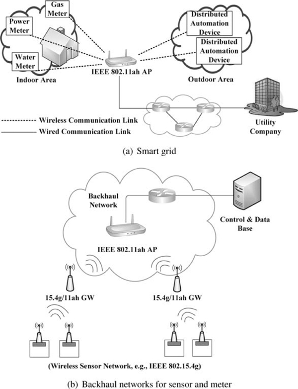
Figure 1 IEEE 802.11ah use cases.
4 PHY Layer
Regarding the 802.11ah PHY features, which are based on the down-clocked operation of IEEE 802.11ac’s PHY, we describe its channelization and various types of transmission modes. As an evolution of 802.11n, to achieve higher data rates, 802.11ac provides 80 MHz, 160 MHz and non-contiguous 160 MHz channel bandwidths in addition to the 802.11n’s 20 MHz and 40 MHz channel bandwidths. Being a 10-times down-clocked version of 802.11ac, IEEE 802.11ah defines 2 MHz, 4 MHz, 8 MHz, and 16 MHz channels. Besides, 1 MHz channel is additionally defined by 802.11ah for the purpose of extended coverage. In the following, we will provide 802.11ah’s PHY features in terms of channelization and transmission modes.
4.1 Channelization
The available sub 1 GHz ISM bands are different depending on countries, and hence, IEEE 802.11ah has defined the channelization based on the respective available wireless spectra in various countries, including the United States, South Korea, China, Europe, Japan, and Singapore. In the following, we outline the 802.11ah channelization in these countries.
As a representative example, we illustrate the channelization in the United States in Figure 2. Total 26 MHz band between 902 MHz and 928 MHz is available in the US, and accordingly, the number of available 1 MHz channels is 26. In order to achieve a higher bandwidth, 802.11ah maintains the same channel bonding method as in 802.11n and 802.11ac, i.e., several adjacent narrower channels are bonded together to yield a wider channel. As a result, 2 MHz channel is composed of two adjacent 1 MHz channels. Similarly, more wider channel bandwidths are supported through channel bonding. The widest channel supported in the US is 16 MHz channel, which is also the widest channel bandwidth supported in the 802.11ah system.
Figure 3 shows the sub 1 GHz spectra specified in the 802.11ah channelization with respect to the involved countries. The channelization for South Korea, which starts from 917.5 MHz and ends at 923.5 MHz, defines 6 MHz bandwidth. The reason for the 0.5 MHz frequency offset is to reduce the possible mutual interference with wireless legacy systems at lower frequencies [13]. The available spectra defined in the 802.11ah channelization for Europe, China, Japan are 863–868 MHz, 755–787 MHz, 916.5–927.5 MHz, respectively, and in Singapore, the specified spectra are composed of two non-contiguous frequency bands, i.e., 866–869 MHz and 920–925 MHz bands. Besides, in Japan, there is also a 0.5 MHz offset, because Japanese spectrum regulations specified the center frequencies of the spectrum instead of start/stop frequencies [14]. These spectra are channelized based on the same rules as shown in the case of the US, i.e., split the radio bands into multiple 1 MHz channels and achieve wider channel bandwidths through channel bonding.
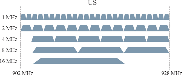
Figure 2 IEEE 802.11ah channelization for the US.
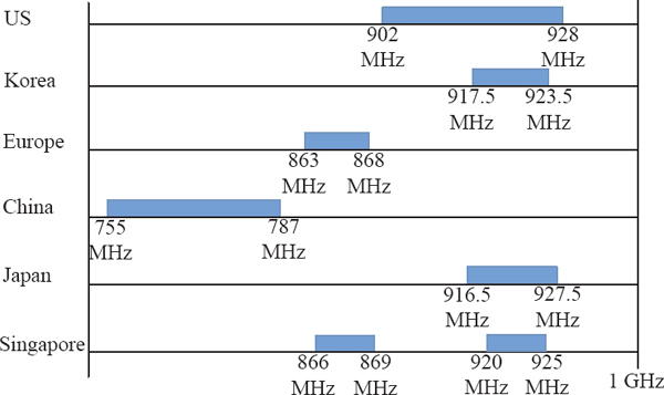
Figure 3 Sub 1 GHz spectra specified in the 802.11ah channelization.
However, since various involved countries have different regulations and available spectra, the maximum channel bandwidths obtained by the channel bonding could be different. Accordingly, the maximum channel bandwidths supported by South Korea, Europe, China, Japan, and Singapore are set to 4 MHz, 2 MHz, 8 MHz, 1 MHz, and 4 MHz, respectively. More detailed information for these countries’ channelization is available in [8].
4.2 Transmission Modes
In 802.11ah, 1 MHz and 2 MHz channels have been adopted as common channel bandwidths such that 802.11ah stations have to support the receptions of them. The PHY layer design can be classified into 2 categories. The first category is the transmission modes of greater than or equal to 2 MHz channel bandwidths and the other is the transmission mode of 1 MHz channel bandwidth.
For the greater than or equal to 2 MHz modes, i.e., 2 MHz, 4 MHz, 8 MHz, and 16 MHz transmissions, the PHY layer is exactly designed based on 10 times down-clocking of 802.11ac’s PHY layer. That is, techniques like Orthogonal Frequency Division Multiplexing (OFDM) and Multi Input Multi Output (MIMO) have been adopted, and Downlink Multi-User MIMO (DL MU-MIMO), which is firstly introduced in the 802.11ac, is also employed by the 802.11ah system. Besides, in 802.11ah, an OFDM symbol duration is exactly ten times of that of 802.11ac, and the number of data tones in 2 MHz, 4 MHz, 8 MHz, and 16 MHz channels in 802.11ah are the same as those in 20 MHz, 40 MHz, 80 MHz, and 160 MHz channels in 802.11ac. The set of supported MCSs is also the same as that of 802.11ac.
Table 1 shows the MCSs and the corresponding data rates using 2 MHz channel with a single spatial stream. NSS represents the number of spatial streams, which is 1 in this case. NSD denotes the number of subcarriers used in data transmission. In the 2 MHz channel, 64 Fast Fourier Transform (FFT) is used to generate an OFDM symbol, and among the 64 subcarriers, the number of subcarriers used to transmit data is 52. NDBPS indicates the number of data bits per symbol, which is calculated by the number of data bits per subcarrier per symbol multiplied by the number of data subcarriers. The right-most column represent the corresponding data rates, which are calculated as the number of symbols per second multiplied by NDBPS . AGuard Interval (GI) is a portion of an OFDM symbol containing redundant data, being used to prevent Inter-Symbol Interference (ISI) in OFDM transmission. In the case of adopting short GI of 4 μs, an OFDM symbol duration becomes 36 μs, whereas, when using normal GI of 8 μs, the OFDM symbol duration becomes 40 μs. Consequently, the data rates achieved by adopting short GI results in approximately 11 % increase in data rates compared to the case of adopting normal GI. Moreover, according to the MCS exclusion-rules of 802.11ac, MCS 9 is not adopted in 20 MHz channel with a single spatial stream. Similarly, in the case of 802.11ah 2 MHz channel with a single spatial stream, the MCS 9 is not valid either.
Those specifications result in that the data rates of 802.11ah are exactly one-tenth of 802.11ac’s data rates due to the ten times extended symbol duration. For instance, when using a single spatial stream and MCS 0 in 2 MHz channel, the data rate is 0.65 Mbps in 802.11ah, which is exactly one-tenth of the data rate achieved in 802.11ac. Moreover, in order to take balance between throughput and power consumption, the maximum number of spatial streams supportable in 802.11ah is up to 4, whereas in 802.11ac, a device can support up to 8 spatial streams.
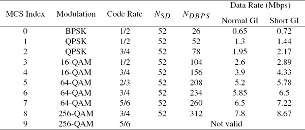
Table 1 802.11ah MCSs and data rates for 2 MHz channel, NSS = 1
For the 1 MHz transmission mode, 802.11ah maintains the same tone spacing as in the case of the former transmission modes, which is 31.25 kHz, resulting in 32 Fast Fourier Transform (FFT), whereas 64 FFT is used in 2 MHz transmission. However, in 1 MHz channel, the number of data subcarriers per OFDM symbol is 24, which is less than a half of data subcarriers in 2 MHz channel. The reason is that when two adjacent narrower channels are bonded together to yield a wider channel, the number of data subcarries become more than double since the guard band between the two bonded channels can be removed.
The goal of designing 1 MHz channel is to extend the transmission range. To this end, a new MCS index, which is called MCS 10, is included for long range transmission in addition to the 802.11ac’s MCSs. This MCS is nothing but a mode of MCS 0 with 2x repetition, by which the transmission range can be enlarged since the symbol repetition increases the reliability of the wireless transmission further.
5 MAC Layer
In 802.11ah MAC layer design, some features are enhanced compared with the existing 802.11 MAC, including improvements related with support of large number of stations, power saving, medium access mechanisms and throughput enhancements. In the following, these MAC layer enhancements are presented.
5.1 Support of Large Number of Associated Stations
In 802.11 system, an AP allocates an identifier called Association IDentifier (AID), to each station during the association stage [15]. In a given network, AID is a unique ID, through which the AP can indicate its associated stations. The possible number of associated stations of an AP is up to 2,007 in legacy 802.11 standard due to the limited length of the partial virtual bitmap of Traffic Indication Map (TIM) Information Element (IE), where each bit indicates the corresponding station’s AID. The TIM IE is used to support stations’ power management, and more descriptions about it will be provided in the next sub-section.
As described in Section 3, in IEEE 802.11ah system, an AP is likely to be associated with much more stations than that in legacy 802.11 networks, and hence, 802.11ah has increased the number of supportable stations to meet such expected requirements.
For increasing the number of supportable stations, a hierarchical AID structure is newly defined in 802.11ah as illustrated in Figure 4. It consists of 13 bits, and accordingly, the number of stations that it can express is up to 213 − 1 (= 8, 191). It is composed of four hierarchical levels, namely, page, block, sub-block, and station’s index in sub-block. That is, each station belongs to a certain sub-block, and each sub-block belongs to a certain block. Similarly, multiple blocks form a page, which is the highest level that can contain up to 2048 stations. This hierarchical AID structure enables us to indicate more stations’AID with a given length of partial virtual bitmap. For example, when we need to indicate multiple stations, we can simply include them in a block or a sub-block and use the block ID or the sub-block ID to indicate them instead of including all of their AIDs.
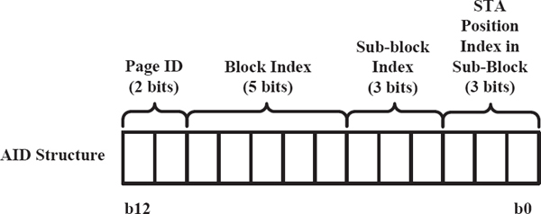
Figure 4 AID structure.
Furthermore, there could be stations with different traffic patterns and/or different locations. If we can easily group these stations based on some specific properties, the wireless resource could be utilized more efficiently. There have been many existing research efforts on clustering algorithms. As a well-known principle, hierarchical structure can be adopted to facilitate the grouping so that the characteristic of hierarchical AID structure makes grouping of the stations much easier. Grouping can be used for various purposes, such as power saving enhancements, resource allocation, and efficient channel access, which will be detailed later.
5.2 Power Saving
The legacy 802.11 standard defines two power management modes. With active mode, a station continually turns on the radio components, i.e., awake state, such that it senses the incoming signal all the time and can also transmit and receive signals. On the other hand, with power saving mode, a station alternates between awake state and doze state, where the station in doze state turns off the radio components such that it cannot sense incoming signals at all. When there are packets destined to a station in doze state, the AP buffers the packets until the station wakes up and requests the delivery of the buffered traffic.
In 802.11 system, AP periodically transmits beacon frame, which contains TIM IE. The partial virtual bitmap field in the TIM IE conveys the information of the existence of buffered traffic destined to power saving stations. Accordingly, a power saving station needs to wake up periodically to receive a beacon, based on which it can check the existence of the buffered packets destined to itself. If it recognizes the existence of buffered traffic, the station then transmits a control frame called Power Saving (PS)-poll frame to the AP to request the delivery of the buffered packets. After finishing the reception of the buffered packets, the power saving station can go back to doze state.
However, several undesirable phenomena could happen, when there exist a large number of stations in a network. One is that the length of the beacon frame could become extremely long due to the excessive length of the partial virtual bitmap in TIM IE. In addition, if the amount of the buffered traffic is too heavy to be accommodated within a beacon interval, some power saving stations inevitably keep in awake state to complete the receptions of their buffered packets.
In order to solve the aforementioned problems, 802.11ah introduces a mechanism called TIM and page segmentation, which works as follows. Firstly, an AP splits the whole partial virtual bitmap corresponding to one page into multiple page segments, and each beacon is responsible for carrying the buffering status of only a certain page segment. Then, each power saving station wakes up at the transmission time of the beacon which carries the buffering information of the segments it belongs to. A new IE called segment count IE is defined to deliver segmentation information, such as the resulting number of segments after page segmentation and the boundary of each page segment.
DTIM beacon is a beacon frame that includes Delivery TIM (DTIM) IE, which is a special type of TIM IE used to indicate the buffering status of group addressed packets (i.e., multicast and broadcast packets). Right after a DTIM beacon transmission, the AP transmits all the pending group addressed packets. Generally, all of the power saving stations wake up to receive DTIM beacons so that they do not miss group addressed packets. In order to let power saving stations know the segmentation information beforehand, the segment count IE is contained in every DTIM beacon which is transmitted periodically over several beacon intervals.
Figure 5 illustrates the usage of the TIM and page segmentation. We assume that a page is composed of 32 stations and the page is divided into 4 page segments since one DTIM beacon interval consists of 4 beacon intervals in this example. Each beacon sequentially carries each page segment, and each beacon interval is used to accommodate traffic delivery of the corresponding page segment. Power saving stations wake up in time to receive the DTIM beacon and then through the information conveyed in segment count IE, they can recognize which beacon contains the partial virtual bitmap of the page segment that they belong to. Afterwards, power saving stations can go back to doze state and wake up again at the transmission time of the beacon frame they should refer to.
As a result, the length of each beacon frame can be shortened because the partial virtual bitmap field of the TIM IE in this case only indicates a certain segment instead of the whole page. Besides, after the reception of the DTIM beacon, power saving stations can only be awake for the beacon with their affiliated segments, and stay in doze state during the other beacon periods, through which the unnecessary energy consumption during excessive awake state can be saved.
In 802.11ah system, power saving stations are categorized into two classes. The first class is called TIM station, which is similar to the concept of power saving mode in legacy 802.11 systm. That is, the packet buffering information of these stations is included in TIM IE. On the other hand, especially for low-powered sensor devices, 802.11ah defines another power saving mode, in which the buffering information is not included in TIM IE assuming that there is no need for them to periodically wake up for the beacon reception. The station operating in this mode is called non-TIM station, and by operating as a non-TIM station, the station can further save the energy consumption compared with the TIM stations, because it can keep in doze state over a longer period without worrying about beacon reception.
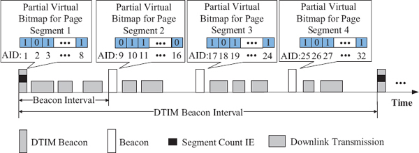
Figure 5 An example diagram of page segmentation.
5.3 Channel Access
802.11ah has introduced some novel channel access mechanisms for both TIM stations and non-TIM stations.
For non-TIM stations, AP may allow them to request buffered downlink traffic or to transmit uplink traffic at anytime upon waking up. However, in such an arbitrary manner, there could be much uncontrollable traffic incurred by these non-TIM stations, which is likely to degrade the network performance. For example, if a large number of stations wake up at the same time, the contention among these stations could results in excessive channel access delays or even collisions.
To make the non-TIM stations’ traffic under control, 802.11ah AP can let them wake up at a predefined time so that the wake-up time of these non-TIM stations and their channel access attempts could be temporally spread out. To exchange the wake up timing information between AP and stations, 802.11ah has defined an IE called Target Wake Time (TWT) IE, which is exchanged by association request and association response frames. In TWT IE, there are four fields, i.e., request type, target wake time, minimum wake duration, and wake interval mantissa, which are used to determine when and how often a station wakes up for downlink and/or uplink transmissions.
More specifically, when there are buffered packets for a non-TIM station, the AP can send to the station a newly defined control frame called Null Data Packet (NDP) paging frame at its target wake time, which contains the information of buffering status. If the station recognizes the existence of buffered packets after successfully receiving the NDP paging frame, it can then request the delivery of the buffered packets by transmitting a PS-poll frame. If the NDP paging frame is not transmitted by the AP at the target wake time, the station can transmit uplink frame if the channel is idle.
For TIM stations, in addition to the existing contention-based channel access mechanisms, e.g., Enhanced Distributed Channel Access (EDCA), 802.11ah has focused its efforts on defining a new type of contention-free channel access mechanism, which is motivated by the increased contention level and severity of hidden terminal problems due to the increased number of stations involved in a network.
As a result, a concept named Restricted Access Window (RAW) has been proposed. An RAW is a time duration composed of several time slots. An AP may indicate to a TIM station a time slot during which the station is allowed to transmit or to receive packets. RAW can be used for various purposes. For example, it can be allocated to a group of TIM stations that have uplink or downlink data packets or be reserved for control frames, e.g., PS-poll.
Besides, in order to indicate the parameters related with RAW allocation, e.g., RAW start time, RAW duration, and the AIDs of the stations to which the RAW is allocated, RAW Parameter Set (RPS) IE is proposed. The RPS IE is optionally included in beacon frame, and each station can recognize the allocated RAW via the RPS.
Moreover, it would be more efficient to allocate time slots only to the stations which are certainly ready to transmit or receive, rather than to all of the TIM stations. In order to enable the AP to adaptively manage the RAW allocation, a new management frame named Resource Allocation (RA) frame has been proposed, which contains the scheduling information of each individual station, through which the station can learn the time slot during which it is allowed to conduct medium access for uplink or downlink transmission. The RA frame is transmitted at the beginning of each RAW and all the stations assigned to that RAW have to wake up to receive it. 802.11ah adds a special field called Uplink Data Indication (UDI) in the PS-poll frame. The UDI is used to indicate the existence of the uplink frame of a station, and a station with no buffered downlink frame, can send the PS-poll with UDI field set to 1, to request the time slot for its uplink transmission. After receiving both normal PS-poll and UDI PS-poll, the AP then can determine how to schedule the uplink and downlink transmissions efficiently, and the scheduling information is contained in the RA frame.
Figure 6 illustrates the uplink and downlink packet delivery procedures by applying the RAW concept. During the first RAW, i.e., RAW 1, AP allocates each TIM station a time slot for PS-poll transmission. We denote the PS-poll with UDI field set to 1 as UDI to differentiate it from a normal PS-poll frame. The station with AID 1, which does not have buffered downlink traffic, sends a UDI to request time resource for its uplink transmission, and the stations with AID 2, AID 3, and AID 5 transmit normal PS-poll frames during the allocated time slot except the station withAID 4. Such unexpected behavior of the station with AID 4 in this example, i.e., not transmitting a normal PS-poll frame, can occur due to the stations’ asynchronous operation with its associated AP or the erroneous reception of a beacon frame. During RAW 2, firstly, the AP transmits an RA frame for delivering the scheduling information for stations with AID 1, AID 2, AID 3, and AID 5, and thereafter, these stations conduct uplink or downlink transmissions during the allocated time slots, respectively.
5.4 Throughput Enhancements
As described earlier, a major deficiency of 802.11ah is its low data rates, and to overcome it, there have been many efforts on throughput enhancements.
The first intention was to design more compact frame formats to reduce protocol overheads, and correspondingly, a more compact MAC header format has been proposed. Figure 7 compares the proposed short MAC header format and the legacy 802.11 MAC header format. For the downlink, the address 1, which is destination MAC address in the legacy MAC header, is replaced with the AID of the destination station in the short MAC header format. Similarly, in the case of uplink, the address 2, which is the MAC address of source station in the legacy MAC header, is replaced with the AID of source station in the short MAC header. In addition, in the short MAC header, the sequence control field is moved before address 3 field. The address 3 field is optionally included in the short MAC header and its inclusion is indicated by the indication bit in Frame Control (FC) field.

Figure 6 An example of uplink and downlink data delivery using RAW.
Moreover, some necessary information contained in Quality of Service (QoS) field and High Throughput (HT) field is moved to Signal (SIG) field in the PHY header and the other unnecessary parts are removed such that there is no QoS and HT fields presented in the short MAC header.Another thing to note here is that there is no duration/ID field in the short MAC header so that virtual carrier sensing is not supported when using short MAC header. By substituting the 6 bytes MAC address with 2 bytes AID and eliminate duration/ID, QoS, and HT fields, it is possible to save at least 12 bytes overhead in both uplink and downlink. This kind of short MAC header should be used after the AID assignment procedure, and is differentiated from the legacy MAC header by setting a new protocol version value in the FC field.
In legacy 802.11 standard, Acknowledgement (ACK) frame includes MAC header and Frame Check Sequence (FCS) field in addition to the preamble of the packet. In order to shorten the ACK frame, 802.11ah has proposed a new ACK frame format called Null Data Packet (NDP) ACK, in which the MAC header and FCS field are eliminated such that the frame only contains PHY header field as illustrated in Figure 8. Besides, the NDP ACK frame is identified by a reserved value of MCS, which is indicated in the SIG field of the PHY header. There are also some other control frames modified to an NDP frame format to reduce the protocol overhead, e.g., Block ACK, Clear To Send (CTS), and PS-poll frames, and these NDP control frames are indicated by other reserved MCS values as in the case of the NDP ACK.
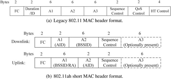
Figure 7 MAC header comparison between 802.11 legacy system and 802.11ah system.
![]()
Figure 8 NDP ACK frame format.
Besides, 802.11ah defines a novel medium access mechanism, by which the channel access delay and ACK transmission overhead are eliminated so that the achieved throughput is increased. In legacy 802.11 standard, the feedback method of a receiver can be requested by the transmitter through ACK indication field. The 2 bits ACK indication field can express 4 different values, three of which had been already defined to indicate feedback methods of normal ACK, block ACK, and no response, respectively, while the last one had been reserved for future usage.
In 802.11ah, the reserved value is defined to indicate another feedback method. With this method, if the receiver has a frame destined to the transmitter, it can notify the successful reception by transmitting its data frame instead of ACK or block ACK. Similarly, if the transmitter successfully receives the receiver’s data frame, it can also reply with its data frame instead of other control frames, and the gap between each transmission is restricted to Short Inter-frame Space (SIFS). Such a method is called speed frame exchange. It speeds up the interchange of frames between AP and stations, because the ACK overhead and channel access delays are eliminated. Figure 9 illustrates an example of sequential transmissions between an AP and a station using speed frame exchange. When a transmitter, i.e., station or AP, sets ACK indication bits to request a data frame as its feedback of successful transmission instead of other feedback methods, the corresponding receiver, i.e., AP or station, replies with data frames until there is no packet to transmit. By applying this method, besides the throughput gain we can obtain by reduced overhead, the power saving stations can save more energy, because in this case, the time for awake state is reduced compared to the normal data transmissions. Moreover, the speed frame exchange scheme is more effective when there are a similar number of uplink and downlink packets, since the ACK transmission could not be replaced unless there are more data packets available.
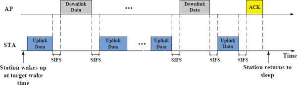
Figure 9 Speed frame exchange.
6 Performance Evaluation
As we mentioned above, 802.11ah provides large transmission coverage, while there have been some efforts on reducing the protocol overheads to overcome its weakness of throughput. To verify these aspects, in this section, the performance of 802.11ah system is evaluated in terms of its transmission range and throughput.
6.1 Transmission Range
We will evaluate the transmission range by comparing the performance of 802.11ah and current 2.4 GHz and 5 GHz 802.11 systems. The transmission range is calculated by only considering path loss effect. At the receiver side, the minimum input level sensitivities specified in 802.11ah, 802.11n, and 802.11ac standard specification are used to determine the minimum received power levels required for successful decoding in 900 MHz, 2.4 GHz, and 5 GHz bands, respectively. Besides, we assume that the transmissions are conducted with a single spatial stream. As proposed in [6], we adopt TGn channel model and 3GPP cellular system simulation channel model in indoor and outdoor environments, respectively. The specific calculating methods are described in [16, 17].
Figure 10 shows the transmission range in indoor and outdoor environments at various frequency bands. Although the maximum transmission power allowed in different region could be different, in this evaluation, we set the transmission power to 200 mW, which is a typical transmission power in 5 GHz 802.11 system. The transmission range is calculated as the distance between transmitter and the receiver, of which the received power is equal to the minimum input level sensitivity specified in each system. The x-axis represents different MCS indexes, and the y-axis represents the transmission range. We compare the transmission range of 802.11ah, 802.11n’s 2.4 GHz system, and 802.11ac’s 5 GHz system, which are indicated here as Fc(900), Fc(2.4), and Fc(5), respectively. Besides, regarding the channel bandwidth, we select 20 MHz channel bandwidth in 2.4 GHz and 5 GHz bands, and 2 MHz channel in 900 MHz band, which are indicated as CBW (20) and CBW (2), respectively. We additionally include the 802.11ah 1 MHz channel, which is denoted as CBW (1). From the results, we observe that regarding the transmission range, the systems operating in outdoor environments generally outperform the systems in indoor environments as we can expect. We also conclude that the transmission range increases as the frequency of the operating band decreases due to the improved propagation characteristic of the wireless signal. One thing to note here is that MCS 10 and MCS 9 are only valid for 802.11ah’s 1 MHz transmission in our results, since these MCSs are excluded by other cases according to the MCS exclusion rule of each system. Besides, the longest transmission range up to 1,013 m is achieved by the 802.11ah system with 1 MHz channel bandwidth in outdoor environment, which is almost 7 times of the 5 GHz system’s outdoor transmission range shown in this result.
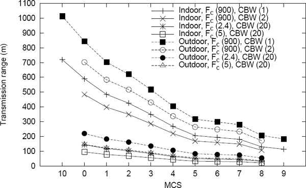
Figure 10 Comparison of transmission ranges with transmission power of 200 mW.
As the maximum transmission power level is different for different countries, we evaluate the 802.11ah transmission range with various transmission power levels. Figure 11 shows the increase of the transmission range as the transmission power increases from 200 mW to 1000 mW. We present the results obtained by transmissions in 1 MHz channel and 2 MHz channel in indoor and outdoor environments. In order to present the longest transmission range of each transmission power, we adopt the most robust MCS in 2 MHz channel, i.e., MCS 0. Besides, apart from MCS 0, we add MCS 10 in 1 MHz channel, which is only applicable to 1 MHz channel. In these results, when we set the transmission power to 1000 mW, the transmission range obtained by 1 MHz transmission with MCS 10 is 1,555 m, which is much longer than the required transmission range, i.e., 1,000 m. Moreover, the increase in the transmission power results in more significant increase in transmission range in outdoor environment than that in indoor environment.
6.2 Throughput Performance
We evaluate the throughput gain achieved by newly defined 802.11ah’s medium access schemes described in this paper, i.e., RAW based channel access and speed frame exchange, through analysis. We also analyze the advantage of adopting the 802.11ah’s compact frame formats.

Figure 11 Transmission range of 802.11ah with different transmission power levels.
Figure 12 shows the analytical results. The x-axis represents MCS indexes and the y-axis represents MAC layer throughput for the case of a single transmitter and a single receiver without channel errors. We assume the transmission is conducted at 2 MHz channel with a single spatial stream as shown in Table 1. The legacy 802.11 channel access scheme, i.e., Distributed Coordination Function (DCF), the RAW based channel access and the speed frame exchange are indicated as Legacy, RAW and SFE, respectively. When using 802.11ah compact frame formats, i.e., short MAC header and NDPACK frame, the legend of each scheme is appended by with compact format, while it is denoted as with normal format otherwise. Besides, due to the traffic pattern of 802.11ah usage model, e.g., smart grid, we set the packet size to a relatively small value, which is 100 bytes in our evaluation. We assume that the MCS of the normal ACK frame is fixed to the most robust MCS, i.e., MCS 0, and the short GI is used for the evaluation.
The results show that speed frame exchange outperforms the other two schemes due to the eliminations of the channel access delay and ACK transmission. Similarly, the RAW based channel access, which is a contention-free channel access scheme, outperforms the legacy 802.11 MAC. Moreover, when using the compact frame format, the throughput achieved by each scheme increases as we can easily imagine. The throughputs presented in this evaluation results are much less than the data rates indicated in Table 1, since we set the packet size to a relatively small value so that the portion of the protocol overhead, i.e., PHY header, MAC header, and ACK transmission, is relatively large. In our evaluation, when using speed frame exchange, the achieved throughput of MCS 8 is nearly 3 times of the throughput achieve by the 802.11 DCF with the same MCS.

Figure 12 Throughput comparison of various MAC schemes.
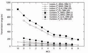
Figure 13 Errata
7 Conclusion
In this paper, we introduce the 802.11ah project in terms of the use cases, PHY design, and MAC enhancements, for which the agreements are already made in drafting works of TGah. We also provide performance evaluation results in terms of transmission range and theoretical MAC layer throughput through theoretical analysis. The transmission range of 802.11ah is much longer than existing Wi-Fi systems, and the throughput can be significantly improved by newly adopted medium access schemes. The standardization of 802.11ah is still on-going, and to complete the standardization, some remaining issues need to be resolved, such as the performance degradation due to the interference caused by neighboring APs. In the near future, we envision that 802.11ah will be used for many emerging applications over very large scale wireless networks.
References
[1] E. Perahia|IEEE 802.11n development: history, process, and technology. IEEE Communications Magazine, 46(7):48–55, Jul. 2008.
[2] |IEEE std. IEEE 802.11ac/D5.0. Part 11: wireless LAN medium access control (MAC) and physical layer (PHY) specifications: enhancements for very high throughput for operation in bands below 6 GHz, Jan. 2013.
[3] D. Halasz|Sub 1 GHz license-exempt PAR and 5C. IEEE 802.11-10/0001r13, Jul. 2010, https://mentor.ieee.org/802.11/dcn/10/11-10-001-13.
[4] D. Halasz, R. Vegt|IEEE 802.11ah proposed selection procedure. IEEE 802.11-11/0239r2, Feb. 2011, https://mentor.ieee.org/802.11/dcn/11/11-11-0239-02-00ah-proposed-selection-procedure.docx.
[5] R. Vegt|Potential compromise for 802.11ah use case document. IEEE 802.11-11/0457r0, Mar. 2011, https://mentor.ieee.org/802.11/dcn/11/11-11-0457-00-00ah-potential-compromise-of-802-11ah-use-case-document.pptx.
[6] R. Porat, et al.|TGah channel model – proposed text. IEEE 802.11-11/0968r3, Jul. 2011, https://mentor.ieee.org/802.11/dcn/11/11-11-0968-03-00ah-channel-model-text.docx.
[7] M. Cheong|TGah functional requirements and evaluation methodology. IEEE 802.11-11/0905r5, Jan. 2012, https://mentor.ieee.org/802.11/dcn/11/11-11-0905-05-00ah-tgah-functional-requirements-and-evaluation-methodology.doc
[8] M. Park|Specification framework for TGah. IEEE 802.11-11/1137r14, Mar. 2013.
[9] E. Wong, et al.|Two-hop relaying. IEEE 802.11-12/1330r0, Nov. 2012, https://mentor.ieee.org/802.11/dcn/12/11-12-1330-00-00ah-two-hop-relaying.pptx.
[10] G. Calcev, et al.|Sectorization for hidden node mitigation. IEEE 802.11-12/0852r0, July 2012, https://mentor.ieee.org/802.11/dcn/12/11-12-0852-00-00ah-sectorization-for-hidden-node-mitigation.pptx
[11] |NIST priority action plan 2. guidelines for assessing wireless standards for smart grid applications, ver. 1.0, Dec. 2010.
[12] |IEEE Std. IEEE 802.15.4g-2012. Part 15.4: low-rate wireless personal area networks (LR-WPANs) amendment 3: physical (PHY) specifications for low-data-rate, wireless, smart metering utility networks, Apr. 2012.
[13] S. Aust, R.V. Prasad, and I.G. Niemegeers|IEEE 802.11ah: advantages in standards and further challenges for sub 1 GHz Wi-Fi. In Proceedings of IEEE International Conference on Communications (ICC), Jun. 2012.
[14] |Association of radio industries and business (ARIB), 950 MHz-band telemeter, telecontrol and data transmission radio equipment for specified low power radio station, english translation, ARIB STD-T96 Ver. 1.0, Jun. 2008.
[15] |IEEE std. IEEE 802.11-2012. Part 11: wireless LAN medium access control (MAC) and physical layer (PHY) specifications, Mar. 2012.
[16] |Further advancements for E-UTRA physical layer aspects, Annex A.2- system simulation scenario. Technical Report 36.814, 3GPP, Mar. 2010.
[17] V. Erceg, et al.|TGn channel models. IEEE 802.11-03/940r4, May 2004.
Biography

Weiping Sun received the B.E. degree of Network Engineering from Dalian University of Technology, Dalian, China in 2010. He is currently working toward a Ph.D. degree in the Department of Electrical and Computer Engineering, Seoul National University, Seoul, Korea. His current research interests focus on IEEE 802.11 WLAN MAC protocol and algorithm design.

Munhwan Choi received the B.S. and M.S. degrees in Electrical Engineering and Computer Science from Seoul National University, Seoul, Korea in 2005 and 2007, respectively. He is currently working toward a Ph.D. degree in the Department of Electrical and Computer Engineering, Seoul National University, Seoul, Korea. His current research interests include algorithmic design and protocol development for various communication systems such as IEEE 802.11 wireless local area networks and 60 GHz wireless personal area networks.

Sunghyun Choi is a professor at the Department of Electrical and Computer Engineering, Seoul National University (SNU), Korea. Before joining SNU in 2002, he was with Philips Research USA. He was also a visiting associate professor at Stanford University, USA from June 2009 to June 2010. He received his B.S. (summa cum laude) and M.S. degrees from Korea Advanced Institute of Science and Technology in 1992 and 1994, respectively, and received Ph.D. from The University of Michigan, Ann Arbor in 1999. His current research interests are in the area of wire-less/mobile networks. He authored/coauthored over 150 technical papers and book chapters in the areas of wireless/mobile networks and communications. He has co-authored (with B. G. Lee) a book entitled “Broadband Wireless Access and Local Networks: Mobile WiMAX and WiFi,”Artech House, 2008. He holds about 100 patents, and has tens of patents pending. He is also currently serving on the editorial boards of IEEE Transactions on Mobile Computing and IEEE Wireless Communications. He has received a number of awards including the Presidential Young Scientist Award (2008); IEEK/IEEE Joint Award for Young IT Engineer (2007); Shinyang Scholarship Award (2011); the Outstanding Research Award (2008) and the Best Teaching Award (2006) from the College of Engineering, SNU; and the Best Paper Award from IEEE WoWMoM 2008.