Hybrid Facial Features with Application in Person Identification
Boonchana Purahong1, Vanvisa Chutchavong1, Hisayuki Aoyama2 and Chuchart Pintavirooj3,*
1Department of Computer Engineering, Faculty of Engineering, King Mongkut’s Institute of Technology Ladkrabang, Thailand
2Department of Mechanical and Intelligent Systems Engineering, University of Electro-Communications, Japan
3Departmet of Biomedical Engineering, Faculty of Engineering, King Mongkut’s Institute of Technology Ladkrabang, Thailand
E-mail: boonchana.pu@kmitl.ac.th; vanvisa.ch@kmitl.ac.th; aoyamaxer@gmail.com; chuchart.pi@kmitl.ac.th
* Corresponding Author
Received 13 October 2019; Accepted 07 May 2020; Publication 17 August 2020
Abstract
This paper presents the hybrid facial feature with identification and verification based on facial images. A query facial image had been taken under different conditions of the facial image of the same person (as the query). The query facial image database was constructed. We have used the technique of three-dimensional (3D) Dlib facial landmarks using a direct linear transform technique. A set of absolute affine invariance had been constructed from a series of the 3D landmark quadruplets, which make the facial identification robust to affine geometric transformation. These 3D facial features serve as a coarse feature depending on each individual facial structure. The construct of the 2D detail features represents the edge facial image confined between the 2D Dlib landmarks. The similarity of the 2D feature is achieved by aligning the 2D query edge image against that of the reference edge image. The geometric transformation matrix is estimated from the 2D Dlib landmarks, where correspondence is well established. An identification/verification cost function using a combination of local 2D facial features and global 3D facial features is utilized to verify and identify a query facial image against a candidate facial image(s). The performance of the algorithm yielding an area of 99.97% perfect classification is represented as a value under the receiver operating characteristic (ROC) curve.
Keywords: Geometric invariance, person identification, face identification, hybrid facial feature, facial image.
1 Introduction
One of the challenging topics of computer vision problems is automated human face recognition. Although nontrivial, it is of considerable practical significance [1]. There are many face recognition applications, including access control, automatic surveillance systems, forensic analysis, fast retrieval of records from databases in police departments,law enforcement agencies, and human–computer interaction [2]. The face recognition is defined as a process that identifies and compares a query face image against all image templates in face database or verifies a person’s identity. An input face characteristic is compared with a face images template from a database [3]. There are two categories in face recognition systems, i.e., two-dimension (2D) and 3D. Details of further research in face recognition, virtual 3D restoration, and automatic detection are presented in Refs. [4–6].
The 2D face recognition [7] feature involves a multidirectional local gradient descriptor for face recognition in a 2D image. It achieves high accuracy, i.e., more than 95% and could identify a person even with sunglasses or expressions. However, the sophisticated algorithm used in this process is time-consuming. Ref. [8] has presented the face recognition technique by using discrete wavelet transform based feature extraction utilizing edge tracked scale normalization for enhanced 2D face recognition. The area ratio and angle of triangle were used for face recognition based on facial landmark detection [9]. A study of distance and slope in 2D image recognition is presented in Ref. [10].
The 3D face recognition technique used fisher vector encoding of local scale-invariant feature transforms and encoding of binary features for video face recognition [11]. This research provided video face recognition as a good performance indicator as the one that is obtained by using SIFT features. However, it is a sophisticated algorithm. Ref. [12] has used multiple kernels local Fisher discriminant analysis for face recognition. It is a powerful analyzer for high-dimensional data. The results on three face databases demonstrate the effectiveness of the proposed algorithm. However, the algorithm can be used only with high-dimensional data, and also reported to be time-consuming [13–15].
The concept of this paper introduces hierarchical person identification by using facial images. A coarse global facial feature is combined with exceptional local facial features. The proposed 3D features are immune to various linear geometric transformations. The excellent local facial features also exploit the Dlib. A region of interest (ROI) is defined as the area confined in the 2D Dlib landmark convex hull. The edge detection is applied for intensity image within the ROI. The facial edge image resembles a facial outline sketch in facial portrait and is robust to lighting conditions. To define the cost function in person identification, the 3D facial alignment and 2D facial image are registered. The proposed facial identification technique based on the 3D facial landmarks is presented as follows. First, the proposed method is quick in terms of processing time, as it is not used as a 3D facial scanner. Second, the proposed facial identification scheme is a hybrid scheme where it combines 2D facial excellent features with 3D facial coarse features. This makes the proposed technique achieve high accuracy for person identification. Third, the proposed 3D facial feature is robust for geometric affine transformation as it is based on absolute affine invariance. Lastly, our 2D facial feature is immune to illumination conditions as it exploits the robustness of edge image to lighting conditions.
This paper is organizing as follows. Section 2 explains the general concept of hybrid facial identification. Section 3 briefly introduces Dlib facial landmark, which is based on a histogram of the oriented gradient. Section 4 describes the 2D- and 3D facial features. Section 5 briefly reviews the direct linear transform process. Results are provided in Section 6. Discussion and conclusion are presented in Sections 7 and 8, respectively.
2 General Concept
A person’s identification is based on a hierarchy scheme with both 2D and 3D facial features as shown in Figure 1. The person’s facial image in a database is used as a reference image. The person to be identified will be denoted as a query image. The facial acquisition data consists of two USB cameras installed on the common rail. The camera’s orientation can be arbitrary. For each person, first, the 2D Dlib facial landmarks are acquired from both the images. 2D facial features’ extraction is then processed in one of the images (right image). Second, the ROI is defined to be facial image bounded within the convex hull of the Dlib facial landmarks. Third, edge detection is applied to the ROI image. The geometric transformation is estimated with the known correspondence between the 2D facial landmarks of the reference and query images. Fourth, the edge image of the query is aligned against the edge image of the reference image. The edge image will be defined as the 2D facial feature that will provide local information on the person’s face. The similarity measure based on distance map error [30] is used to compute and identify. For the 3D facial feature, the used 3D acquisition technique called the direct linear transform is utilized to extract the 3D Dlib landmarks. The technique is superior to the traditional stereoscopic technique. The two used cameras do not need to be identical in both camera characteristics and orientation. Fifth, geometric invariance-based features are extracted from the 3D landmark points. The geometric invariance feature is constructed from a volume confined between 3D landmark quadruplets. It will be served as a 3D facial signature. The 3D facial signature is contributing as a global feature that is based on a person’s facial structure. Sixth, for combined 2D facial features and 3D feature signature, the derived hybrid facial features can be used for personal identification.
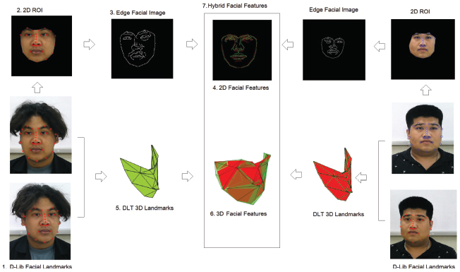
Figure 1 Overall person identification process.
3 Facial Landmarks Detection
Image-based automated facial landmark detection has been the topic of active research and has numerous applications, including facial identification, facial expression analysis, such as facial palsy, sleep apnea [16–19], face animation, 3D face reconstruction and registration [20–23], feature-based face recognition, verification, face tracking, and head gesture understanding [24–28]. The number of facial landmarks can be varied depending on intended applications. The low-level application particularly focuses on detection of faces and requires only primary landmarks, such as nose tip, four eyes, and two mouth corners. The first facial landmarks contribute to 20–30 landmarks. For higher-level tasks, such as facial expression analysis, secondary facial landmarks of 40–50 landmarks will be combined. The proposed 2D facial landmarks are primary landmarks constituting 30 landmarks, including nine landmarks for face contour, six eyebrows, four eyes, nine noses, and two mouth landmarks. Figure 2 shows the 2D facial landmarks.
In general, the process of detecting facial landmarks is divided into two steps: first, locating the face in the image and second, detecting fundamental feature structures in the facial region, e.g., mouth, right and left eyebrows, nose, right and left eyes, and jaw. Face detection in the first step exploits the histogram of oriented gradients (HOG), a useful feature descriptor in computer vision widely used for object recognition. The central concept of this approach is to locate gradient orientation in a localized portion of an image. The algorithm overview in this regard comprises six steps as listed hereunder:
(i) Divide the image into small spatial cells with an aspect ratio of 1:2, to apply 64 × 128 patches of an image.
(ii) Calculate the gradient (Sobel) images.
(iii) Calculate the HOG in 8×8 cells.
Figure 2 The 30 Dlib facial landmark points.
(iv) Perform block normalization by using an histogram so that they are not affected by lighting conditions.
(v) Calculate the HOG feature vector by using 36×1 vector concatenated on a large vector.
(vi) Detect face based on the HOG feature vector by using the dominant direction of the histogram that captures the shape of facial components.
Once the person’s face is localized, critical facial structures in the face region are determined based on the algorithm described in Ref. [29]. Also, there is an eminently sound library called the “Dlib” [31], which is used to extract facial landmarks accurately.
4 Hybrid Facial Features
The hybrid facial features used for personal identification exploit both the 2D and 3D features. The 2D and 3D facial features can be considered as local information and global information, respectively. The 2D facial features in a hierarchy facial identification are 2D facial edge profiles contained in the ROI. The 3D facial features exploit the geometric invariance constructed from the 3D facial landmarks.
4.1 2D Facial Feature
The 2D facial feature is based on an edged facial image which is invariant to lighting conditions. Figure 3 explains the 2D facial features. First, the Dlib facial landmarks are extracted. Then, define the ROI as the area to be confined within the convex hull of facial landmarks. Edge detection is then performed in the ROI and can be used as 2D facial features. To apply the 2D facial feature, we need to align the ROI face image of the reference against that of the query image. In order to align the ROI edged image of the original Figure 3(b) against the query image, we need to compute the geometric transformation matrix, T. Let the landmark points in the original (X) Figure 3(a) and in query image (Y) related by
| (1) |
where
| (2) |
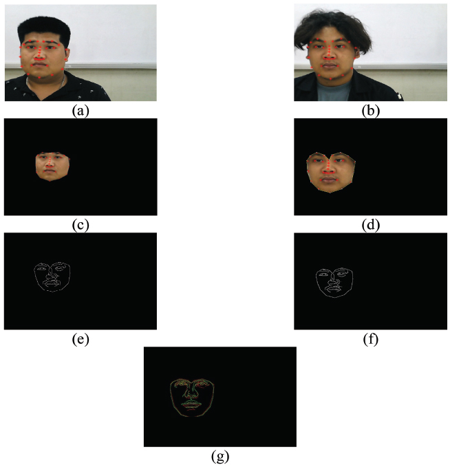
Figure 3 The 2D facial feature (a), (b) Dlib facial landmark on the reference image and query image, respectively; (c) to (d) ROI face image of the reference and that of the query image; (e) to (f) ROI facial edged image of the reference and that of the query image; (g) ROI facial edged image of the reference aligned against that of the query image.
| (3) |
| (4) |
The estimated transformation matrix T using the minimized mean square error (MMSE) scheme can defined as
| (5) |
and then derivative of Eq. (1) is taken with respect to T
| (6) |
| (7) |
| (8) |
| (9) |
The transformation matrix, T, can be estimated from
| (10) |
After the geometric transformation matrix T is estimated, the query edged image is aligned against that of the original image, i.e., Figure 3(e). The similarity is then computed using the distance map error [30].
4.2 3D Facial Features Based on Geometric Invariances
The geometric invariances are properties of curve and surface that are preserved under specific class of rigid transformation. The geometric invariances can be classified into two types, i.e., an absolute invariance and a relative invariance. The absolute invariances are properties that remain unchanged before and after geometric transformation. In contrast, relative invariances are properties before and after geometric transformation that are not the same but related by some function. Under the 2D rigid transformation, length and angle bounded between two adjacent lines and areas is the absolute invariance [32]. However, the 2D rigid transformation, similarity, affine transformation, lines, and angles are no longer preserved. The area of the corresponding triangles becomes a relative invariant, with the two corresponding areas being related to each other through the determinant of the linear transformation matrix T shown in Figure 4:
| (11) |
where Area(ΔA′B′C′) and Area(ΔABC) are the areas of the triangular patch A′B′C′ and ABC, respectively
| (12) |
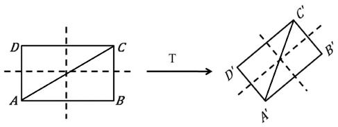
Figure 4 The absolute invariance derived from the area ratio of two corresponding triangular patches [32].
where Area(ΔB′C′D′) and Area(ΔBCD) are the areas of triangular patch B′C′D′ and BCD, respectively. By taking the ratio of Eq. (3) with Eq. (3), the area ratio can be derived as
| (13) |
In the case of the 3D geometric invariance, volume is a relative affine invariance, whereas the volume ratio is an absolute affine invariance.
The 3D geometric invariance as a 3D facial feature is determined as follows: first, the 3D facial landmark with 30 points based on the HOG from both the query and reference faces is recorded. The volume of the confined area is next to be computed within some four determined landmark points (quadruplets) on both faces to derive a sequence of volume in a triangular-based pyramid shape. Furthermore, take the ratio of volume between the consecutive volume quadruplets. The sequence of volume ratio is then served as a facial signature to be used for personal identification. Figure 5 demonstrates the construction of 3D facial features, which serve as a facial signature. Figure 6 shows the selection of 13 triangular-based pyramids constructed from some determined 3D facial landmark quadruplets used as our 3D facial features.
5 3D Acquisition Based on Direct Linear Transform
In this section, the DLT is determinded by extracts of the 3D coordinates of the object from multiple photographs taken at an arbitrary pose. The DLT is more flexible than the traditional well-known stereoscopic technique, e.g., used camera and camera orientation are not the same. The DLT technique for the 3D acquisition requires two steps, i.e., camera calibration and 3D acquisition. In the first step, camera calibration can be done by analyzing the photograph of the reference box with a known coordinate placed at the same position of the object, as shown in Figure 6(a). A photograph taken by a camera undergoes a linear transformation from 3D to 2D projective space as Eq. (14)
| (14) |
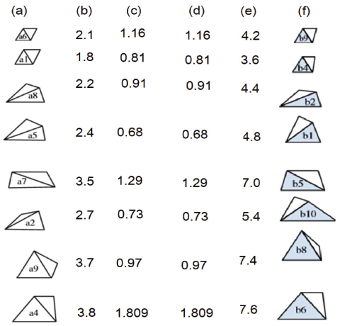
Figure 5 The construction of 3D facial features: (a), (f) sequence of volume confined within some four determined landmark points on reference and query facial data, respectively; (b), (e) volume of each triangular-based pyramid; and (c), (d) sequence of absolute affine invariance of reference and query facial data, respectively.
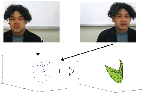
Figure 6 Thirteen triangular-based pyramids constructed from some determined 3D facial landmark quadruplets used as 3D facial features.
where
| (15) |
while M is the projection matrix, K, R, and T are respectively the intrinsic parameter matrix, rotation matrix, and translation matrix between the camera coordinate system and object coordinate system. The 3D coordinates [x, y, z, 1] and corresponding image coordinate [u, v, w] can be solved by the matrix M of each camera.
In the second step, the calibration object is replaced with the object to be acquired for a 3D coordinate. (u′,v′) and (u″,v″) are the image coordinates of the landmarks from camera 1 and 2, respectively. The 3D coordinates of landmarks can be estimated by solving the following homogeneous Eq. (16)
| (16) |
where are the row ith of the projection matrix M of the first camera and are the row ith of the projection matrix M of the second camera.
6 Experiments and Results
The experiments and results are involved with two experiments, i.e., first camera acquisition and second performance test.
6.1 Camera Calibration and 3D Acquisition Test
As described in the previous section, the 3D landmark acquisition is based on the DLT technique. One of the crucial steps of the DLT is camera calibration. A simple-geometry calibration phantom is taken by each camera. The projection matrix M in Eq. (15) can be estimated by the 3D coordinates and corresponding image points. Figures 7(a) and 7(b) show the calibration cube’s image with the dimensions 10.5 cm × 10.5 cm × 10.5 cm. The origin of world coordinate system (coordinate [0, 0, 0]), the eight vertex coordinates of the calibration box can be determined. The circular dots in Figure 8(a) or 8(b) represent the eight vertices’ corresponding image points. These data sets can then be used to estimate the projection matrix, M [33]. Once the projection matrix is estimated, the projected image points of the 3D coordinate of the eight vertices are computed. The results are plotted as the star dot in Figure 8(a) or 8(b). The process is call reprojection.
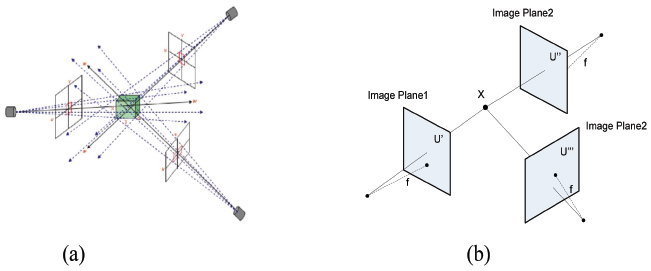
Figure 7 The camera calibration (a) calibration cube’s image and (b) 3D landmark acquisition of facial landmark point X.
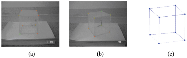
Figure 8 Camera calibration: (a) Reprojection of camera 1; (b) Reprojection of camera 2; and (c) 3D acquisition result of calibration phantom.
The superimposition of the real image coordinate and the computed image coordinates of the calibration phantom demonstrate the success of camera calibration, as show in Figures 8(a) and 8(b). Once the camera calibration is performed, the two projection matrices can be used to estimate the 3D coordinate of the phantom box. The result is show in Figure 8(c).
6.2 Performance Test of Person Identification with Hybrid Feature
6.2.1 Hardware setup
The 3D facial landmark acquisition system is shown in Figure 8. Two Logitech C270 HD Vid 720P USB cameras are mounted on the 3D-printed camera holder with the center point camera at 10 cm. The two cameras are connected to Intel i5 notebook via USB ports. The written OpenCV program is used as data acquisition for both cameras. The test subject will sit in front of the camera with a distance of 100 cm from the camera. The visual studio C++ is used to acquire the 2D Dlib facial landmark of the two facial images. The 2D Dlib facial landmark coordinate is recorded and forwarded to the MATLAB program for further analysis, including the 2D and 3D facial features, and the statistical analysis of the experiment.
6.2.2 Receiver operating characteristic
In this experiment, 80 subjects are tested, which allows us to get 3,200 facial images by using two 2D-cameras, as shown in Figure 9. The well-known parameters for classification were evaluated, including true positive (TP), false positive (FP), true negative (TN), and false negative (FN). Thus, we can compute the accuracy, specificity, and sensitivity, which are defined as follows:
| (17) |
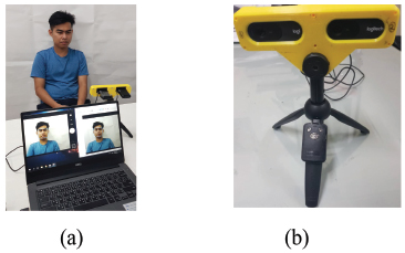
Figure 9 Experimental setup (a) person model and (b) Logitech C270 HD Vid 720P camera.
| (18) |
| (19) |
Table 1 shows a comparison of the results from separated 3D features and 2D features. Table 2 shows the result of the hybrid feature obtained from the combination of the 3D feature and 2D feature. Alignments of the 3D facial features of some facial samples are demonstrated in Figure 10, whereas the 2D facial feature registration of some facial samples is show in Figure 11.
6.2.3 Hybrid facial feature
The cost function for hybrid facial feature is defined as
| (20) |
where α is the weighting factor. The value is between 0 and 1, and the increased value of α result in an increased factor of the 3D facial features and vice versa. The optimization values of α are shown in Table 2. The optimal α is at 0.3, where it achieves the best accuracy, sensitivity, and specificity of 99.78%, 80.41%, and 98.98%, respectively.
Table 1 The face recognition with 3D facial features and 2D facial features
| Results | 3D feature | 2D feature |
| Accuracy | 80.55% | 95.99% |
| Sensitivity | 65.98% | 95.88% |
| Specificity | 80.70% | 95.99% |
Table 2 The face recognition with hybrid feature different weighting factor (α)
| α | Accuracy | Sensitivity | Specificity |
| 0.1 | 99.72% | 73.20 | 97.54% |
| 0.2 | 99.77% | 77.32% | 98.41% |
| 0.3 | 99.78% | 80.41% | 98.98% |
| 0.4 | 99.76% | 88.66% | 99.87% |
| 0.5 | 99.21% | 88.66% | 99.32% |
| 0.6 | 96.64% | 91.75% | 96.69% |
| 0.7 | 89.65% | 94.85% | 89.59% |
| 0.8 | 75.25% | 95.88% | 75.03% |
| 0.9 | 60.13% | 59.73% | 68.03% |
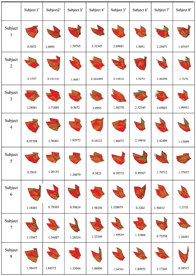
Figure 10 Alignment of 3D facial features with reference against query and error between 3D facial features.
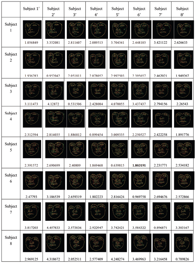
Figure 11 Registration of 2D facial features with reference against query and distance map error.
7 Discussion
In this section, we discuss the parameters, 3D facial features, data acquisition, and performance.
7.1 Parameter α
According to proposed hybrid scheme of facial identification, the cost function is defined by Eq. (20). The experimental results demonstrate the effects and performance of the system. In this case, there is a significant change in lighting conditions, as it may decrease and hence increase the weight of the 2D facial features. The 2D facial features are based on the edged image, which is immune to changes in lighting conditions. On the other hand, in the case where there is a problem of transformation change, e.g., the person head is tilted, it may result in an increased value of α. Consequently, the optimization of α is needed but it is dependent upon data acquisition condition.
7.2 3D Facial Features
The 3D facial features are based on the absolute affine invariance, which is the ratio of two pyramidal volumes. The effect of geometric transformation is cancelled out according to Eq. (3). Hence, the 3D facial feature alignment is not required. For an excellent presentation, however, the 3D facial features in Figure 9 are aligned using the transformation matrix estimate from the 3D landmark points. The cost function is based on the 3D feature after the alignment.
7.3 Data Acquisition
The 3D landmark acquisition is based on the DLT and hence requires camera calibration. After the camera calibration, the camera orientation should be fixed. Any disturbance to the 3D landmark acquisition would result in calibration of the two cameras.
7.4 Performance
The hybrid facial feature with 0.3 can achieve the performance of personal identification with an accuracy of 99.78%. The sensitivity is not as good as accuracy. This fact reflects the noticeable false positive error.
8 Conclusion
In this paper, the hybrid feature algorithm was proposed for person identification based on facial image with the 2D and 3D facial features. In the 3D facial features, two USB cameras are installed on the rail in arbitrary orientation to take two facial images. The 3D Dlib facial landmarks are extracted using a direct linear transform. A sequence of pyramidal volume constructed from a series of four landmark points is obtained and used to derive a sequence of absolute affine invariance to serve as 3D facial features. The 2D facial features are constructed from the edge image of the area of interest, which is the area confined with the 2D Dlib facial landmarks. The combination of the 2D and 3D facial features is used in the cost function for person identification. The advantages of the proposed hybrid feature for person identification system are as follows. First, the system is invariant to affine transformation as the facial features are based on geometric invariance. Second, the system is immune to changes in the light condition as the 2D features are based on edge image, which is known to be robust to lighting conditions. Third, the processing time is quick as the 3D acquisition system does not use a 3D scanner. Fourth, the hybrid system is based on a hierarchy scheme where the 3D features serve as coarse or global features, whereas the 2D features serve as excellent or local features. Finally, our system is affordable as it used only two USB cameras, whereas the previous work exploited a 3D laser scanner. The performance of the proposed system has been tested with 80 persons and achieved an accuracy of 99.78%.
References
[1] G. Shalini, M. Mia, and B. Alan, “Anthropometric 3D Face Recognition,” International Journal of Computer Vision, 90:331–349, 2010.
[2] S.Z. Li and A.K. Jain, “Handbook of Face Recognition,” Springer, 2011.
[3] A. Andrea, N. Michele, R. Daniel, and S. Gabriele, “2D and 3D Face Recognition: A Survey,” Pattern Recognition Letters, 28:1885–1906, 2007.
[4] S. Takeda, T. Terada, and M. Tsukamoto, “Implicit context awareness by face recognition,” Journal of Mobile Multimedia, Vol. 8, No. 2, pp. 132–148, 2012.
[5] P. Dedkova and S. Popelka, “Virtual 3d restoration of an extinct village and its eye-tracking assessment,” Journal of Mobile Multimedia, Vol. 11, No.3&4, pp. 181–192, 2015.
[6] A. Basiri, S. Marsh, T. Moore, and P. Amirian, “Automatic detection of points of interest using spatio-termporal data mining,” Journal of Mobile Multimedia, Vol. 11, No.3&4, pp. 193–204, 2015.
[7] V.C. Kagawade and S.A. Angadi. “Multi-directional local gradient descriptor: A new feature descriptor for face recognition,” Image and Vision Computing, 83:39–50, 2019.
[8] B.P. Rinky, P. Mondal, K. Manikantan, and S. RamaChandran, “DWT based Feature Extraction using Edge Tracked Scale Normalization for Enhanced Face Recognition,” Procedia Technology, 6:344–353, 2012.
[9] A. Juhong and C. Pintavirooj, “Face recognition based on facial landmark detection,” Biomedical Engineering International Conference, 1–4, 2017.
[10] T. Ozseven and M. Dugenci, “Face recognition by distance and slope between facial landmarks,” International Artificial Intelligence and Data Processing Symposium, 1–4, 2017.
[11] Y. Martínez-Díaz, N. Hernández, R.J. Biscay, L. Chang, H. Mendez-Vazquez, and L. E. Sucar, “On Fisher vector encoding of binary features for video face recognition,” Journal of Visual Communication, and Image Representation, 51:155–161, 2018.
[12] Z. Wang and X. Sun, “Multiple kernel local Fisher discriminant analysis for face recognition,” Signal Processing, 93:1496–1509, 2013.
[13] E. Vezzetti, F. Marcolin, and G. Fracastoro, “3D face recognition: An automatic strategy based on geometrical descriptors and landmarks,” Robotics and Autonomous Systems, 62:1768–1776, 2014.
[14] H. Drira, B. Ben Amor, A. Srivastava, M. Daoudi and R. Slama, “3D Face Recognition under Expressions Occlusions, and Pose Variations,” IEEE Transactions on Pattern Analysis and Machine Intelligence, 35:2270–2283, 2013.
[15] S. Soltanpour, B. Boufama, and Q.M. Jonathan, “A survey of local feature methods for 3D face recognition,” Pattern Recognition, 72:391–406, 2017.
[16] S. Anping, X. Guoliang, D. Xuehai, S. Jiaxin, X. Gang, Z. Wu, “Assessment for facial nerve paralysis based on facial asymmetry,” Phys. Eng. Sci. Med, 40(4): 851–860, 2017.
[17] A. Tabatabaei Balaei, K. Sutherland, P. Cistulli, and P. de Chazal, “Automatic detection of obstructive sleep apnoea using facial images,” International Symposium on Biomedical Imaging, 215–218, 2017.
[18] B. Johnston, A. McEwan, and P. de Chazal, “Semi-automated nasal PAP mask sizing using facial photographs,” IEEE Engineering in Medicine and Biology Society, 1214–1217, 2017.
[19] Y. Cohn, J. Tian, and T. Kanade, “Recognizing action units for facial expression analysis,” IEEE Trans. Pattern Anal, 23(2):97–114, 2001.
[20] K. Liu, A. Weissenfeld, J. Ostermann, and X. Luo, “Robust AAM building for morphing in an image-based facial animation system,” Int. Conf. on Multimedia and Expo, 933–936, 2008.
[21] U. Park and AK. Jain, “3D face reconstruction from stereo images,” Workshop on Video Processing for Security, 41–41, 2006.
[22] AA. Salah, N. Alyüz, and L. Akarun. Registration of 3D face scans with average face models. Electron. Imag., 17(1), 2008.
[23] N. Pears, T. Heseltine, and M. Romero, “From 3D point clouds to pose-normalised depth maps,” Comput. Vis, 89(2):152–176, 2010.
[24] A. Lanitis, CJ. Taylor, and TF. Cootes, “Automatic face idenitification system using flexible appearance models,” Image Vis. Comput,13(5):393–401, 1995.
[25] L. Wiskott, JM. Fellous, N. Kruger, and C. von der Malsburg, “Face recognition by elastic bunch graph,” IEEE Trans. Pattern Anal. Mach. Intell, 7:775–779, 1997.
[26] F. Dornaika and F. Davoine, “Online appearance-based face and facial feature tracking,” Pattern Recognition, 814–817, 2004.
[27] J. Cohn, A. Zlochower, JJJ. Lien, and T. Kanade, “Feature-point tracking by optical flow discriminates subtle differences in facial expression,” Automatic Face and Gesture Recognition, 396–401, 1998.
[28] H. ßnar Akakßn and B. Sankur, “Analysis of head and facial gestures using facial landmark trajectories,” Biometric ID Management and Multimodal Communication, 105–113, 2009.
[29] V. Kazemi and J. Sullivan, “One millisecond face alignment with an ensemble of regression trees,” IEEE Conference on Computer Vision and Pattern Recognition, 1867–1874, 2014.
[30] C. Pintavirooj, F. S. Cohen and W. Iampa, “Fingerprint Verification and Identification Based on Local Geometric Invariants Constructed from Minutiae Points and Augmented With Global Directional Filter Bank Features,” IEICE Transactions on Information and Systems, 97(6):1599–1613, 2014.
[31] Dlib c++ Library. (n.d.). Retrieved Nov 17, 2019, from Dlib c++ Library: http://dlib.net/
[32] Z. Yang and F.S. Cohen, “Image registration and object recognition using affine invariants and convex hulls,” IEEE Trans. Image Process, 8(7):934–946, 1999.
[33] T. Chaichana, M. Sangworasil, C. Pintavirooj, S. Aootaphao, “Acclerate a Dlt Motion Capture System with Quad-Tree Searching Scheme,” International Symposium on Communications and Information Technology, 2006.
Biographies

Boonchana Purahong received his M.Eng. degree in information engineering from the King Mongkut’s Institute of Technology Ladkrabang, Bangkok, Thailand. He has joined the department of computer engineering, faculty of engineering, King Mongkut’s Institute of Technology Ladkrabang, Thailand. He is currently an associate professor and interested in pattern recognition and image processing.

Vanvisa Chutchavong received her Ph.D. degree in electrical engineering from the King Mongkut’s Institute of Technology Ladkrabang, Bangkok, Thailand. She has joined the department of computer engineering, faculty of engineering, King Mongkut’s Institute of Technology Ladkrabang, Thailand. She is currently an associate professor and interested in the filter circuit.

Hisayuki Aoyama received his Ph.D. degree in informatics and engineering from the Tokyo Institute of Technology, Tokyo, Japan. Currently, he is working as a professor in the Department of Mechanical Engineering and Intelligent Systems, Graduate School of Informatics and Engineering. He is interested in micro/precision engineering and micrometrology as well as its industrial and biomedical applications.

Chuchart Pintavirooj received his B.Sc. and M.Sc. degrees from the Mahidol University, Bangkok, Thailand in 1985 and 1989, respectively. In 1995, he received another master’s degree in biomedical engineering from the Worcester Polytechnic Institute, MA, USA. In 2000, he earned a Ph.D. degree in biomedical engineering from the Drexel University, Philadelphia, USA. He joined the Department of Biomedical Engineering, Faculty of Engineering, King Mongkut’s Institute of Technology Ladkrabang, Bangkok, Thailand. He is currently an associate professor. His research interests include image reconstruction, image classification, and image restoration.
Journal of Mobile Multimedia, Vol. 16_1-2, 245–266.
doi: 10.13052/jmm1550-4646.161212
© 2020 River Publishers