Improved Next-Generation Radio Access Networks Using a Centralized Opto-Electronic Oscillator
Mehmet Alp Ilgaz*, Kristjan Vuk Baliž and Boštjan Batagelj
Trzaska cesta 25, Faculty of Electrical Engineering, University of Ljubljana, Slovenia
E-mail: mehmet.ilgaz@fe.uni-lj.si; kristjan.vuk-baliz@fe.uni-lj.si; bostjan.batagelj@fe.uni-lj.si
*Corresponding Author
Received 30 November 2021; Accepted 20 January 2022; Publication 05 April 2022
Abstract
Next-generation 5G and 6G radio access networks (RANs) require millimetre-wave (mm-W) oscillators to generate extremely low phase-noise signals for the frequency up-conversion and down-conversion in radio units (RUs). The opto-electronic oscillator (OEO) is an outstanding candidate for generating a high-purity mm-W signal in a centralized radio access network (C-RAN) where the distributed base-stations are dislocated from the digital units (DUs) and there are only RUs on the remote side. In this paper we propose placing an OEO in the central-office, while distributing its signal from there to multiple RU base-stations through the mobile front-haul network using a radio-over-fibre (RoF) transmission approach. This new approach was used in experiments that proved the smaller degradation of the phase noise compared to a degradation of 6 dB for the well-known frequency-doubling electrical oscillator in the RU. In addition, we present the signal-strength degradation due to fibre dispersion in mm-W signal distribution, as well as the challenges in long-term stability and multimode operation. We propose solutions to overcome these drawbacks and make our new approach useful for a centralized carrier signal distribution in next-generation RANs.
Keywords: 5G radio access network, opto-electronic oscillator, chromatic dispersion, optical front haul, phase noise.
List of Notations and Abbreviations
| CPRI | Common public radio interface |
| CU | Central unit |
| CW | Continuous wave |
| C-RAN | Centralized radio access network |
| DU | Distribution unit |
| D-RAN | Distributed radio access network |
| EDFA | Erbium-doped fibre amplifier |
| FSR | Free spectral range |
| GHz | Gigahertz |
| LO | Local oscillator |
| MHz | Megahertz |
| mm-W | Millimetre wave |
| MZM | Mach-Zehnder modulator |
| ODN | Optical distribution network |
| OEO | Opto-electronic oscillator |
| PIC | Photonics integrated chip |
| RAN | Radio access network |
| RF | Radio frequency |
| RoF | Radio-over-fibre |
| RU | Radio unit |
| SSB | Single-side band |
| SMF | Single-mode fibre |
| SMSR | Side-mode suppression ratio |
| SSA | Signal-source analyser |
| VNA | Vector-network analyser |
| 5G | Fifth generation |
| 6G | Sixth generation |
1 Introduction
The steady increase in the volume of data transmitted over public mobile networks [1] due to new services based on multimedia communications requires an update to a new technological generation that will have more of the electromagnetic spectrum available and use it more efficiently. With the long-term evolution (LTE) technology increasingly crowding the radio-frequency spectrum with machine-to-machine (M2M) communication [2], 5G and 6G must use the spectrum more effectively [3], as well as operating in new frequency bands. Millimetre-wave (mm-W) signals are expected to be used in the next-generation 5G and 6G RANs, while micro-wave passband frequencies are used in the current 4G RANs. In Figure 1, the frequency-spectrum allocation for various wireless technologies is shown, including micro-waves and mm-Ws, which relate to the range between 30 GHz and 300 GHz. This higher mm-W frequency bandwidth has its own unique challenges [4], such as their generation in low-noise oscillators and the transmission of such high-bandwidth signals to the base-stations, which consist of a radio receiver/transmitter and serve as the hub of the mobile network.

Figure 1 Coverage of the micro-wave and millimetre-wave bands in the RF spectrum.
Radio-over-Fibre (RoF) [5, 6] is one of the promising alternative solutions for the transmission of a high-bandwidth analogue signal from a digital unit (DU) to the base-station, containing only the radio unit (RU) of a centralized radio access network (C-RAN) [7]. It uses low-loss and broadband optical fibre [8] for the analogue transmission, as opposed to digital transmission, where the standardized common public radio interface (CPRI) [9, 10] is used. Apart from the advantage of there being no bandwidth increase due to the signal’s conversion to digital form, RoF also makes it possible to establish the communication without a local oscillator (LO) in each RU’s base-station, as shown in Figure 2.
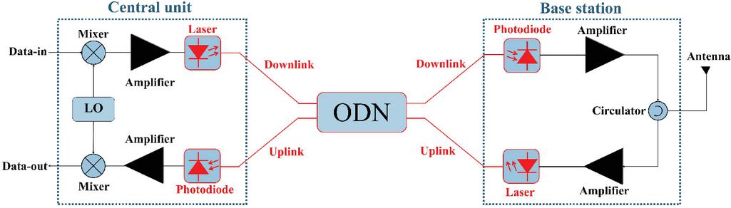
Figure 2 Radio-over-fibre approach to next-generation 5G and 6G RAN front hauls.
In the well-known approach shown in Figure 2, the LO is in the central-office and the broadband data signal is, after the up-conversion, transmitted to the base-station via an optical distribution network (ODN). While the ODN itself relaxes the requirement for the number of LOs needed, there are open issues with the generation of the low-noise carrier signal.
In contrast to RoF, in the currently used topology of the 4G distributed radio access network (D-RAN), each base-station requires a LO for the frequency up-conversion and down-conversion of the data signal [11]. Thus, the synchronization mechanism in current mobile and wireless front-haul networks is more complex and comes with other challenges, such as temperature stabilization of the LO in each base-station.
Several different approaches to carrier-signal distribution in RANs have been presented in [12–15], but all of them suffer from increased complexity and signal-performance degradation. For example, the solution proposed in [15] uses an electrical oscillator at the central-office and an optical fibre to distribute the signal to the remote sites, but requires an additional high-speed converter from the electrical to the optical signal at the central location. Therefore, we propose a new, alternative approach to distributing the carrier signal from the central LO without an additional electrical-to-optical conversion.
The well-known electrical oscillators have the disadvantage that their phase noise is multiplied by the square of the frequency-multiplication factor N [16].
| (1) |
This means that the phase noise is increased by a factor of four (6 dB) as the frequency is doubled [17]. Such phase-noise degradation has a negative impact on the performance of next-generation 5G and 6G RANs, limiting the system data rates and the spectral efficiency. It is well known that the state-of-the-art technology with electrical oscillators does not perform well in the mm-W range.
Probably the best alternative to an electrical oscillator in this regard is the opto-electronic oscillator (OEO), a well-known way to generate a low-phase-noise signal in the micro-wave and mm-W ranges. To eliminate the increase in phase noise by 6 dB at each frequency doubling, in this research we propose the use of a low-phase-noise oscillator and a novel signal distribution. The centrally generated low phase noise is, without an electro-optical conversion, distributed from the central-office, where the OEO would be located in a controlled environment.
The main aim of this paper is to perform an experiment on the distribution of mm-W signals from the central unit to the base-station over an optical distribution network and to show that the low phase noise is not increased by more than 6 dB with a 20-km distribution fibre. This has not been tested before. In addition, this paper addresses new challenges in mm-W distribution over optical fibre and presents a universal solution for improved, next-generation RANs using a centralized OEO.
The paper is organized as follows. In the next section, the working principle of the OEO is described briefly as well as how the next-generation RAN can benefit from employing an OEO in the central-office. In the third section, the challenges of centralized carrier-signal distribution are discussed, and solutions are presented. In the fourth section a universal solution is proposed for the centralized carrier-signal distribution. The conclusion section is dedicated to summarizing the research and suggesting future work.
2 Improving Next-Generation RANs with An Opto-Electronic Oscillator
2.1 The Opto-Electronic Oscillator
The OEO consists of an optical resonator with electrical feedback components. The typical configuration for a single-loop OEO is shown in Figure 3. It contains optical and opto-electronic devices such as a laser diode, an electro-optic modulator, an optical fibre and a photodiode, while an electrical bandpass filter and an electrical amplifier are cascaded in the feedback loop of the oscillator. The electrical amplifier is used to compensate for the optical and electrical losses, whereas the electrical bandpass filter is included in the loop to determine the oscillation frequency. When the Barkhausan conditions are met, the OEO begins to oscillate due to the noise power that is present. One of the main benefits of the OEO is its ability to provide optical and electrical outputs simultaneously without requiring any additional conversion. In developing our new approach for distributing the oscillator signal, we will use the direct optical output of an OEO and distribute the oscillator signal in the optical domain without requiring electro-optical conversion.

Figure 3 Single-loop OEO with electrical feedback components.
Therefore, the OEO is one of the best candidates for providing a carrier signal from the central-office to each base-station [18, 19]. It can generate a signal with ultra-low phase noise in the micro-wave and mm-W ranges. The lowest phase noise achieved with an OEO is 163 dBc/Hz at a 6-kHz offset from the carrier signal [20]. In addition, an OEO in the W-band was recently reported [21]. The phase-noise performance that is so good in the OEO is achieved by using a long delay line in the oscillator loop. The quality factor of the OEO is described as follows:
| (2) |
where Q is the quality factor, L is the length of the optical fibre, is the speed of light in a vacuum, f is the frequency and n is the fibre’s refractive index.
2.2 New Micro-wave Prototype of the Opto-electronic Oscillator in a RAN
In this subsection of the paper we report on our experimental work carried out to examine the new possibility of centralized carrier-signal generation using an OEO and its distribution to a remote base-station. The micro-wave OEO is placed in the central-office and its signal is distributed to the base-station via an optical distribution network (ODN). The aim of this experiment was to evaluate the phase-noise degradation of the carrier signal received at the base-station. The experimental setup shown in Figure 4 consists of a central unit, an ODN, and a base-station. The central unit employs a single-loop OEO with a 1550-nm laser having a Mach-Zehnder modulator (MZM), 15 km of single-mode fibre (SMF), an optical divider, a photodiode with a bandwidth of 11.5 GHz, an electrical amplifier, and an electrical bandpass filter with a main mode of 10.5 GHz. The ODN has an erbium-doped fibre amplifier (EDFA), an optical splitter, and a 20-km SMF. The base-station has a photodiode with a bandwidth of 11.5 GHz and a signal-source analyser (SSA) for measuring the phase noise.

Figure 4 Prototype implementation of a micro-wave OEO in a RAN.
The OEO prototype was constructed for a micro-wave frequency of 10.5 GHz because of the availability of suitable components and the necessary measurement equipment to evaluate its performance, including the phase-noise profile. In any case, the micro-wave results should be valid for mm-Ws, since the phase-noise characteristics of the OEO are independent of the operating frequency [22]. In our experiment the optical distance between the central-office and the base-station is varied from 10 km to 20 km, since the maximum geographical distance in a 5G RAN is not expected to exceed 20 km. The phase-noise measurements are shown in the graph in Figure 5.
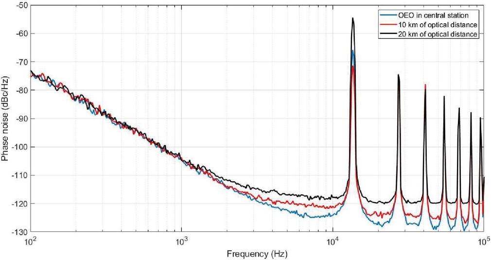
Figure 5 Phase-noise comparison of the OEO in the central-office and its distribution via the ODN, where the optical distances are 10 km and 20 km.
As can be seen from Figure 5, the phase-noise degradation of the OEO signal is measured to be about 4 dB, at an offset of 1 kHz and 6 dB at 10 kHz from the carrier signal. This degradation of the phase noise is due to the noise profile of the EDFA, linear Rayleigh scattering, and non-linear phenomenon in the optical fibre [19]. However, the OEO has a stable phase-noise characteristic with the operating carrier frequency. In other words, the OEO has a phase noise characteristic independent of the operating frequency. This can be considered as one of the main advantages of the proposed idea. On the other hand, the phase noise degrades by 6 dB for each doubling of the frequency if electric oscillators were used. Therefore, the use of an OEO in the RAN should be reasonable for the generation of mm-W signals. Since the degradation of the phase noise is small, these preliminary results can be considered as a good reference point for the final prototype of a centralized OEO for a 5G RAN.
3 Possible Challenges of the Centralized OEO Signal’s Distribution via An ODN
In this section of the paper the possible challenges of the mm-W OEO signal’s distribution in next-generation RANs are discussed. The dispersion penalty, the side-mode suppression ratio (SMSR) and long-term stability are the main anticipated challenges.
3.1 Dispersion Penalty in the C-Band
The chromatic dispersion is dominant in the intensity-modulated optical links, where its value is around 16–17 ps/(nm.km) at 1550 nm (C-band) for standard single-mode optical fibres. The dispersion penalty is defined in Equation (3) [23].
| (3) |
where is the velocity of light in a vacuum, is the fibre-dispersion coefficient, is the wavelength of the optical carrier, and is the modulation frequency.
Since the chromatic dispersion is very dominant for mm-W signals, the dispersion penalty should be overcome in an ODN, distributing the central OEO’s signal. One promising solution is to employ a tuneable dispersion-compensation module (TDCM) in each base-station [18]. Figure 6 shows an experimental study with a mm-W signal of frequencies up to 45 GHz being distributed over an optical fibre of 20 km. The experimental setup shown in Figure 6 is formed by an analogue optical link, a TDCM, and vector network analyser (VNA). The VNA is used to provide the continuous micro-wave and mm-W carrier signals up to 45 GHz. The analogue optical link is composed of a 1550-nm continuous-wave (CW) laser with a MZM, a 20-km SMF, and a photodiode.
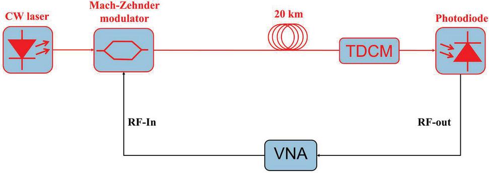
Figure 6 Experimental setup for a dispersion-penalty measurement.
The experiment was carried out with both the TDCM excluded (blue line) and included (red line) at the receiving end. The experimental results are given in Figure 7.
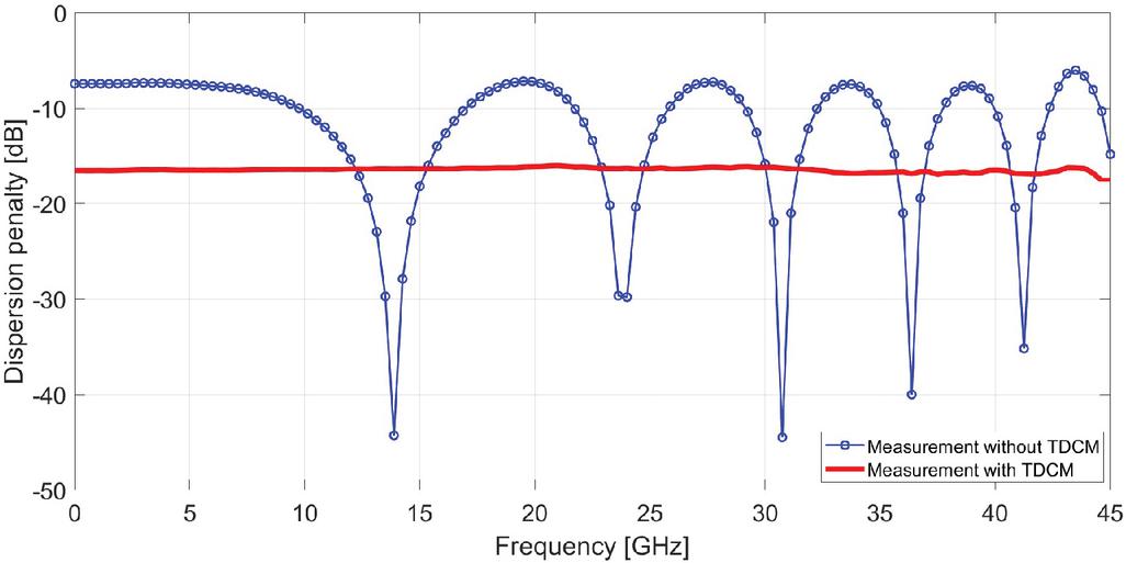
Figure 7 Dispersion-penalty measurements with and without the TDCM where the RF signal is transmitted with an optical delay line.
Based on the measured data presented in Figure 7, the TDCM could be an effective solution to avoid the dispersion penalty. The results support the idea that the dispersion penalty can be avoided if the base-station has a TDCM. The TDCM should be tuned to the actual optical distance between the CU and the base-station. Since each base-station has a different optical distance to the CU, it would be nice to have a self-acting system. This can be achieved by using a PID controller and an electrical power meter [18]. The electrical power meter is used to measure the RF output power of the photodiode in the base-station, and the PID controller is used to tune the TDCM to achieve the maximum output RF power measured by the power meter.
Since the solution using the TDCM might increase the complexity of the base-stations of next-generation RANs, a further improvement can be made by applying single-side-band (SSB) modulation, which is another approach to avoiding the dispersion penalty in the mm-W range. The SSB modulation can be achieved by including a dual-drive Mach-Zehnder modulator (MZM) [24] in the OEO’s loop, or placing an optical filter [25] at the optical output of the OEO’s loop or by applying a phase-shift method [26].
3.2 Long-term Stability
The long-term stability (i.e., the frequency drift) is another critical challenge influencing the OEO’s performance in a RAN. The temperature dependence of the optical fibre and the electrical bandpass filter are the main reasons for the frequency drifting in the OEO. The temperature variations during the day can cause a change in the oscillator’s frequency. For instance, the free-running OEO has a frequency drift of 8 ppm/K [27]. The frequency drift can have negative consequences for the up- and down-conversion of the frequency, which could result in missing the key target points of next-generation RANs. Therefore, the central-office of the RAN should be temperature stabilized. Moreover, the distributed signal’s frequency at the base-station might be influenced by a variation of the ambient temperature. Therefore, certain parts of the ODN and the base-stations should be temperature stabilized. For better long-term stability of the OEO, additional techniques such as a feedback-control loop [28] could be combined with the oscillator.
3.3 Multimode Operation
Multimode operation is another crucial criterion for evaluating the performance of high-frequency oscillators. The OEO does include an electrical bandpass filter to choose the main oscillation frequency and eliminate the other modes in the RF spectrum. However, due to the practical limitations of the electrical bandpass filter’s design and construction, other (side) modes are only attenuated to a limited degree and are still visible in the RF spectrum. This could lead to a mode hopping of the oscillator due to a frequency drift. If the mode hopping problem is not properly addressed, the OEO could start oscillating at a different side-mode frequency [28]. Therefore, the side modes should be eliminated with additional techniques. A quality multiplier is one of the best candidates for improving the SMSR [29]. With this approach a 20-dB improvement of the SMSR was achieved for a 3-GHz OEO.
The OEO employs a long optical fibre in order to have a long delay that provides a high Q, lowering the phase-noise characteristics. On the other hand, having a long delay line reduces the free spectral range (FSR), which causes the side modes to come closer to the main oscillation mode. This makes it more difficult for the electrical bandpass filter to suppress the side modes. Thus, the SMSR is lowered if the optical delay length is increased. The trade-off between the SMSR and the phase noise can be solved (or the optimal solution can be found) with the help of an adjustable OEO configuration with a selectable delay-line length and electrical bandpass filter. An OEO based on optical fibre path selector [30] could be temporarily established in every C-RAN as a verification setup to find the optimal delay-line length. This also helps in selecting the best electrical bandpass filters to optimize the SMSR and the phase noise. Once the optimal choice is made, the C-RAN can be constructed accordingly, i.e., with the chosen fixed delay-line length and an electrical filter.
4 Improving a Next-Generation Radio Access Network by Employing a Wideband Frequency-Tuneable Opto-Electronic Oscillator
In this section of the paper we propose the final implementation of the OEO in next-generation RANs. Yielding the preliminary results, we considered the centralized carrier-signal generation based on a micro-wave single-loop OEO and its distribution with an ODN. The phase-noise degradation presented in Figure 5 speaks in favour of the centralized signal generation with an OEO in next-generation 5G and 6G RANs. However, for a universal solution, the single-loop OEO would not be the best candidate. First, the single-loop OEO employs an electrical bandpass filter that is only tuneable over a narrow range of a few MHz. Since there are different proposals on the operating frequency of the carrier signal, a wideband frequency-tuneable OEO could be the right candidate. Wideband-tuneable OEOs [31–33] have tuneable micro-wave resonators and/or tuneable micro-wave photonic filters to adjust the central operating frequency. They can be adjusted from a few GHz to tens of GHz with stable phase-noise characteristics. As an example, in [31] a wideband-tuneable OEO based on a dispersion-compensation fibre is introduced. The reported phase-noise characteristic is less than -110 dBc/Hz at a 10-kHz offset from the carrier frequency between 3 GHz and 42 GHz. Finally, the universal solution is presented in Figure 8 and includes a wideband-tuneable OEO in the central unit of a next-generation RAN.
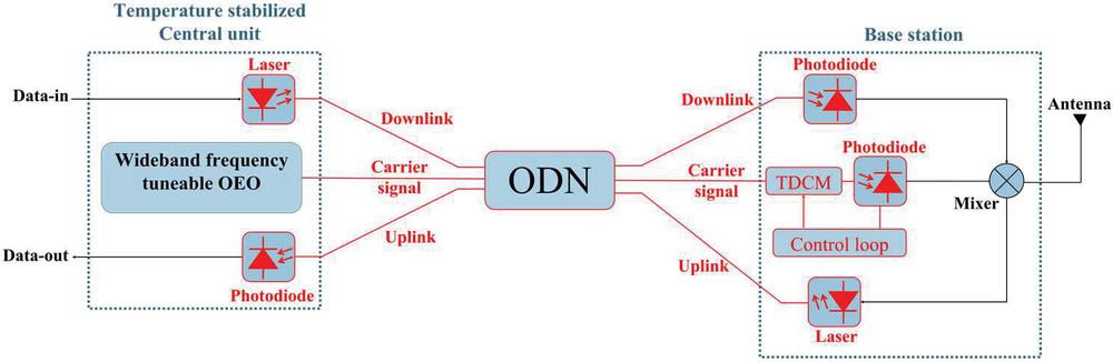
Figure 8 Central carrier-signal distribution of the OEO via an ODN by having a wideband OEO in the central-office of a 5G RAN.
Namely, the wideband-tuneable OEO is proposed for the CU of a RAN. The main carrier signal is generated by the wideband-tuneable OEO and distributed via an ODN. Each OEO is tuned in terms of frequency according to the requirements of the C-RAN and/or the region/country, since some countries would like to have both sub-6 GHz and mm-W for 5G RAN. The CU should be in a temperature-stabilized environment. The purpose of the temperature stabilization is to improve the long-term stability of the carrier signal. The replacement of the oscillator in the CU provides another advantage of lowering the electrical power consumption. With the proposed idea, shown in Figure 8, only the CU requires temperature stabilization, which is an environment-friendly solution compared to the temperature stabilization of each base-station (if the LO was to be employed in the base-station). The TDCM is employed in each base-station to compensate for the chromatic dispersion in the C-Band. The automatic control loop is preferred so as to provide self-tuning of the system.
For future research, integrated micro-wave photonics would be beneficial for a 6G RAN improvement. The integrated OEO was introduced in 2017 [34]. This is the first implementation of a fully integrated OEO on a photonic integrated chip (PIC). Unfortunately, with the current state of the art, there is still no wideband-tuneable, fully integrated OEO, but it is likely to be possible in the coming years. Thus, we believe that in a 6G RAN, a fully integrated, wideband OEO will be introduced, which will decrease the size of the CU.
5 Conclusion
In this study an improvement to next-generation 5G and 6G RANs is proposed by employing a centralized signal generation with an OEO. The carrier signal is distributed from the CU to multiple base-stations using an ODN. This decreases the total number of oscillators in the RAN and thus simplifies the base-stations. In addition, the electrical power consumption of the RAN might be reduced, which can be considered as an additional benefit to the environment. Furthermore, unlike electrical oscillators such as quartz resonators (their phase noise becomes significantly degraded in the mm-W region), an OEO features stable phase-noise characteristics that are independent of the frequency.
On the other hand, the distribution of the OEO signal via an ODN has possible challenges to overcome. One of the main challenges is the dispersion-penalty limitation in the C-Band. The dispersion penalty can be avoided by applying a SSB modulation. Alternatively, a tuneable dispersion-compensation module (TDCM) can be used to compensate for the chromatic dispersion in the C-Band.
The preliminary results of the micro-wave OEO signal distribution in the RAN are presented here. The phase-noise degradation measured for the micro-wave OEO could be acceptable. Because of the phase-noise stability of the OEO we expect a similar degree of degradation with the mm-W OEO.
The selection of the carrier frequency would be another challenge for a centralized OEO’s signal distribution. Since the operating frequency changes from country to country, a wideband-tuneable OEO is a good candidate for a universal solution. In the literature it has already been shown that wideband frequency-tuneable OEOs operating from micro-waves to mm-W exhibit a stable or low degradation of the phase-noise characteristics. Therefore, the wideband OEO could contribute to an improvement of next-generation RANs.
Future work may be devoted to a deeper investigation of the phase-noise degradation in the RAN. The degradation of the phase noise may be caused by Rayleigh scattering, the non-linear properties of the optical fibre, and the noise profile of the EDFA. The characteristics of each component in the RAN should be studied to develop an idea for better stabilization to minimize the phase-noise degradation. In addition, the integrated micro-wave photonics would also be helpful to improve the expectations of 6G RAN. The wideband-integrated OEO could be implemented in a next-generation 6G RAN for optimal performance.
Acknowledgements
The work presented in this article was carried out within the FiWiN5G Innovative Training Network, which received funding from the European Union’s Horizon 2020 Research and Innovation Programme 2014–2018 under the Marie Skłodowska-Curie Action grant agreement No. 642355. The authors also acknowledge the financial support from the Slovenian Research Agency under grant J2-3048 and research core funding No. P2-0246.
References
[1] IMT traffic estimates for the years 2020 to 2030. ITU, Switzerland, Rep. M.2370-0, Jul., 2015. [Online]. https://www.itu.int/dms\_pub/itu-r/opb/rep/R-REP-M.2370-2015-PDF-E.pdf
[2] Ouaissa, M., and A. Rhattoy. 2018. New Method Based on Priority of Heterogeneous Traffic for Scheduling Techniques in M2M Communications over LTE Networks. Int. J. Intell. Eng. 116:209–219.
[3] Nidhi, A. M., and R. Prasad. 2021. Spectrum Sharing and Dynamic Spectrum Management Techniques in 5G and Beyond Networks: A Survey. J. Mob. Multimed. 17: 65–78.
[4] Lopez, A. V., A. Chervyakov, G. Chance, S. Verma, and Y. Tang. 2019. Opportunities and Challenges of mmWave NR. IEEE Wirel. Commun. 26: 4–6.
[5] Radio-over-fibre (RoF) technologies and their applications, ITU-T Series G: Transmission systems and media, digital systems and networks, Supplement 55, (07/2015)
[6] Batagelj, B., L. Pavlovic, L. Naglic, and S. Tomazic. 2011.Convergence of Fixed and Mobile Networks by Radio over Fibre Technology. Info. MIDEM 41: 144–149.
[7] K. Tanaka and A. Agata, ‘Next-generation optical access networks for C-RAN’, Optical Fiber Communications Conference and Exhibition (OFC), USA, pp. 1–3, Jun., 2015.
[8] Batagelj, B., V. Janyani, and S. Tomazic. 2014. Research Challenges in Optical Communications Towards 2020 and Beyond. Infor. MIDEM 44: 177–184.
[9] Common Public Radio Interface (CPRI); Interface Specification, CPRI Specification V7.0 (2015-10-09).
[10] Common Public Radio Interface: eCPRI Interface Specification, eCPRI Specification V2.0 (2019-05-10).
[11] Sadjina, S., R. S. Kanumalli, A. Gebhard, K. Dufrêne, M. Huemer, and H. Pretl. 2018. A Mixed-Signal Circuit Technique for Cancellation of Interferers Modulated by LO Phase-Noise in 4G/5G CA Transceivers. IEEE Trans. Circuits Syst. I Regul. Pap. 65: 3745–3755.
[12] Ye, C., L. Zhang, M. Zhu, J. Yu, S. He, and G. Chang. 2012. A Bidirectional 60-GHz Wireless-Over-Fiber Transport System With Centralized Local Oscillator Service Delivered to Mobile Terminals and Base Stations. IEEE Photonics Technol. Lett. 24: 1984–1987.
[13] Z. Samoud, A. Hraghi, and M. Menif,‘A performance comparison between lumped, distributed and optical phase locked local oscillator used in the photonic generation of millimeter-wave signals for radio over fiber systems ’, Proc. SPIE 11031, Integrated Optics: Design, Devices, Systems, and Applications V, 110311A, Czech Republic, Apr., 2019.
[14] A. Qasim, T. Mehmood, U. Ali, Q. U. Khan, and S. Ghafoor, ‘Dual-ring radio over fiber system with centralized light sources and local oscillator for millimeter-wave transmission’, International Multi-topic Conference (INMIC), pp. 1–5, Pakistan, Nov., 2017
[15] T. Marozsak, T. Berceli, G. Jaro, A. Zolomy, A. Hilt, S. Mihaly, E. Udvary, and Z. Varga, ‘A new optical distribution approach for millimetre wave radio’, International Topical Meeting on Microwave Photonics, pp. 63–66, USA, Aug., 1998.
[16] M. Vidmar, ‘Noise in Radio/Optical Communications’, Proc. IBIC’18, pp. 1–5, China, Sep., 2018.
[17] Z., Ali, F. Athley, J. Medbo, U. Gustavsson, G. Durisi, and X. Chen. 2018. Chapter 4 – Mathematical Modeling of Hardware Impairments. In 5G Physical Layer, Principles, Models and Technology Components, A. Zaidi, F. Athley, J. Medbo, U. Gustavsson, G. Durisi, and X. Chen eds. Academic Press, pp. 87–118.
[18] Ilgaz, M. A., K.V. Baliz, and B. Batagelj. 2020. A Flexible Approach to Combating Chromatic Dispersion in a Centralized 5G Network. Opto-Electron. Rev. 28: 35–42.
[19] Ilgaz, M. A., A. Lavric, and B. Batagelj. 2021. Phase-Noise Degradation of an Optically Distributed Local Oscillator in a Radio Access Network. Radioengineering. 30: 10–15.
[20] D. Eliyahu, D. Seidel, and L. Maleki, ‘Phase noise of a high performance OEO and an ultra low noise floor cross-correlation microwave photonic homodyne system’, IEEE International Frequency Control Symposium, pp. 811–814, United States of America, Sept., 2008.
[21] Hasanuzzaman, G. K. M., S. Iezekiel, and A. Kanno. 2020. W-Band Optoelectronic Oscillator. IEEE Photonics Technol. Lett. 32: 771–774.
[22] Yao, X. S. and L. Maleki. 1996. Optoelectronic microwave oscillator. J. Opt. Soc. Am. B 13:1725–1735.
[23] Schmuck, H. 1995. Comparison of optical millimetre-wave system concepts with regard to chromatic dispersion. Electron. Lett. 31:1848–1849.
[24] Smith, G. H., D. Novak, and Z. Ahmed. 1997. Overcoming chromatic-dispersion effects in fiber-wireless systems incorporating external modulators. IEEE Trans. Microw. Theory Tech. 45:1410–1415.
[25] F. Falconi, C. Porzi, S. Melo, A. Nottola, S. Tirelli, G. B. Preve, M. Sorel, and A. Bogoni, ‘Wideband Single-Sideband Suppressed-Carrier Modulation with Silicon Photonics Optical Filters’, International Topical Meeting on Microwave Photonics (MWP), pp. 1–4, Canada, Nov., 2019.
[26] Loayssa, A., D. Benito, and M. J. Garde. 2001. Single-sideband suppressed-carrier modulation using a single-electrode electrooptic modulator. IEEE Photon. Technol. Lett. 13: 869–871.
[27] D. Eliyahu, K. Sariri, A. Kamran, and M. Tokhmakhian, ‘Improving short and long term frequency stability of the opto-electronic oscillator’, Proceedings of the 2002 IEEE International Frequency Control Symposium and PDA Exhibition, pp. 580–583, United States of America, May, 2002.
[28] Bogataj, L., M. Vidmar, and B. Batagelj. 2014. A Feedback Control Loop for Frequency Stabilization in an Opto-Electronic Oscillator. J. Light. Technol. 32: 3690–3694.
[29] Bogataj, L., M. Vidmar, and B. Batagelj. 2016. Opto-Electronic Oscillator With Quality Multiplier. IEEE Trans. Microw. Theory Tech. 64: 663–668.
[30] Ilgaz, M.A., A. Lavric, T. Odedeyi, I. Darwazeh, B. Batagelj. 2020. Adjustable testing setup for a single-loop optoelectronic oscillator with an electrical bandpass filter. Turk. J. Electr. Eng. Comput. Sci. 28: 1293–1302.
[31] J. Wo, A. Wang, J. Zhang, D. Zhang, Y. Wang, P. Du, W. Cong, and L. Yu, ‘Wideband tunable microwave generation using a dispersion compensated optoelectronic oscillator’, Opto-Electronics and Communications Conference (OECC) and Photonics Global Conference (PGC), pp. 1–2, Singapore, Aug., 2017.
[32] Teng, C., X. Zou, P. Li, W. Pan and L. Yan. 2020. Wideband Frequency-Tunable Parity-Time Symmetric Optoelectronic Oscillator Based on Hybrid Phase and Intensity Modulations. J. Light. Technol. 38:5406–5411.
[33] Wang, Y., X. Jin, Y. Zhu, X. Zhang, S. Zheng and H. Chi. 2015. A Wideband Tunable Optoelectronic Oscillator Based on a Spectral-Subtraction-Induced MPF. IEEE Photon. Technol. Lett. 27: 947–950.
[34] J. Tang, T. Hao, W. Li, N. Zhu, M. Li, D. Domenech, R. Banos, P. Munoz, and J. Capmany, ‘An integrated optoelectronic oscillator’, International Topical Meeting on Microwave Photonics (MWP), pp. 1–4, China, Oct., 2017.
Biographies

Mehmet Alp Ilgaz received a bachelor degree in Electrical and Electronics Engineering from Yeditepe University in 2012 and a master’s degree in Electronics Engineering at the University of Bologna in 2015. He received his PhD from the University of Ljubljana in 2020 for Opto-electronic Oscillators in Radio Access Networks. His research interests include radio-frequency communications, opto-electronics, and integrated optics.

Kristjan Vuk Baliž received his master’s degree from the Faculty of Electrical Engineering, University of Ljubljana, Slovenia, in 2019. He is currently employed as an assistant teacher at the Faculty of Electrical Engineering in Ljubljana. His research interests include microwave photonics, electromagnetic radiation and wave propagation in telecommunications and numerical analysis of electromagnetic phenomena inside waveguide structures.

Boštjan Batagelj received his PhD from the University of Ljubljana in 2003 for work on optical-fiber non-linearity measurements by four-wave mixing. Currently, he is an associate professor at the University of Ljubljana, Faculty of Electrical Engineering and a member of the international organizations IEEE and OSA. As a researcher he works in the Radiation and Optics Laboratory in the Information and Communications Technology Department. His current research interests include work on the physical layer of optical transport and optical access networks, including the convergence with radio systems and components. He is named as an inventor on ten patents.
Journal of Mobile Multimedia, Vol. 18_5, 1425–1444.
doi: 10.13052/jmm1550-4646.1855
© 2022 River Publishers