Blending Real and Virtual Objects in Augmented Reality Environments
Lidiane Teixeira Pereira, Jairo Francisco de Souza and Rodrigo Luis de Souza da Silva*
Computer Science Department, Federal University of Juiz de Fora, Brazil*
E-mail: lidianepereira@ice.ufjf.br; jairo.souza@ice.ufjf.br; rodrigoluis@gmail.com
*Corresponding Author
Received 05 January 2022; Accepted 25 March 2022; Publication 05 July 2022
Abstract
Although Augmented Reality applications are becoming increasingly popular, the lack of visual realism in rendering still remains an open problem due to its computational cost. Physically-based algorithms can generate renderings with a high degree of photorealism, and they are becoming popular after the recent development of hardware accelerators. This work shows how to integrate Augmented Reality frameworks with ray tracing frameworks to create scenes with high-quality, real-time reflections and refractions, with emphasis on the blending of virtual objects to the real environment. To support the interaction between real and virtual elements, a textured cube using images from the real environment must be provided. Our framework does not add processing overhead to the application when comparing the use of the proposed middleware to the use of ray tracing frameworks alone. We will show that with our approach, photorealistic augmented reality rendering can be achieved in real time without the use of any special equipment.
Keywords: Augmented reality, photorealism, ray tracing.
1 Introduction
Despite the popularization of Augmented Reality (AR), some old problems related to this technology persist, such as photorealistic rendering, as pointed out by [1]. The lack of realism in rendering can cause a substantial negative impact on visualization in several types of applications in which, ideally, virtual objects should be indistinguishable from real objects. The field addressing this problem is renderization in augmented reality, which is also growing recently. Only at International Symposium on Mixed and augmented reality (ISMAR), works on this topic corresponded to 12.5% of the total papers between 2008 and 2017 against 1.9% in the previous decade [2]. However, there is a small number of works addressing photorealism in AR, unlike photorealism in Virtual Reality (VR), such as the work by [3] that assesses the impact of visual realism in terms of presence in a virtual environment or the work by [4] that studies the impact of the rendering quality of the virtual environment when performing simulated tasks within it.
Many of the techniques aiming to increase the quality of the rendered image in AR are based on rasterization and, sometimes, fail to correctly simulate the reflection of the light on specular or transparent surfaces. A better rendering can be produced when realistic interactions between surfaces and light are perceived. Close and medium-range reflections are essential for a realistic representation of virtual objects in this context [5]. A perfect blend between virtual and real objects should include the following aspects: real lights should illuminate virtual objects; virtual objects must cast shadows on the real environment; reflections and refractions must be rendered correctly; and occlusions between real and virtual object must be handled correctly [6].
Physically-based rendering techniques such as ray tracing (RT) and path tracing can produce results with a high level of visual realism for specular and transparent surfaces. These techniques are widely used by the film industry for offline rendering [7]. Due to its computational cost, only after the development of graphics cards equipped with hardware acceleration and modern ray tracing frameworks, this technology has become viable for real-time rendering and popular in the gaming industry. Nowadays, these frameworks can even generate images in Full HD at 60 fps [8].
Since AR applications render virtual elements in real-time [9], it was impossible to integrate ray tracing with AR until recently since the processing was very time-consuming and made real-time unfeasible. With the possibility of using ray tracing for real-time rendering in several graphic applications, it also became possible to integrate it with AR frameworks. Through ray tracing algorithms, virtual elements could be rendered more visually realistic and similar to real elements. Through the integration between Augmented Reality and ray tracing, it would be possible to increase the visual photorealism of AR applications.
In a previous work, we proposed the ARRay-Tracing middleware core features to integrate Augmented Reality and ray tracing [10]. We now present a huge leap forward towards a better integration between virtual and real objects. We also extend our previous work by introducing the middleware usage with two different modern ray tracing frameworks, Optix1 and VKRay,2 combined with the Augmented Reality framework ARToolkitX.3 The main contributions of this article are (i) an extended version of the framework adding the ability to receive images of the real environment to allow better blending between real and virtual objects and (ii) the demonstration of the proposed modularity through the use of two distinct ray tracing frameworks.
This work is organized as follows: Section 2 presents the related work. In Section 3, we present the concepts that support the construction of the the middleware. Section 4 presents the extended version of our middleware and workflow, while Section 5 presents the results. Finally, Section 7 present our concluding remarks.
2 Related Work
Over the years, several techniques have been used to increase the visual realism of Augmented Reality applications, but there is a lack of works addressing ray tracing algorithms [5]. This section presents a discussion on ray tracing articles related to this work.
The article [11] presented a method for interactive illumination of virtual objects under time-varying lighting in augmented reality applications and introduced a graphics rendering pipeline based on a real-time ray tracing paradigm. Using a ray tracer previously developed by some of the authors in association with an augmented reality framework, the proposed pipeline was capable of providing high-quality rendering with real-time interaction between virtual and real objects, such as occlusions, soft shadows, and reflections. The tests presented in this work show that their proposed solution got a maximum value of 74 fps for the simplest scenario, where there was no shadow and using a single primary ray. With the insertion of the shadows, the value obtained for the same scenario decreased to 40 fps.
In [12] an algorithm based on irradiance caching and Differential Rendering to produce an augmented reality application for realistic interior design was presented. Their algorithm runs at interactive frame rates and produces a high-quality result of diffuse light transport. Also, the proposal combines ray tracing and rasterization to achieve high-quality results, preserving interactivity. The authors used the Optix framework and ray tracing to calculate direct illumination by the camera. The tests presented in this work show that their solution achieved 31 fps.
The authors in [13] presented a solution to get close and medium-range glossy reflections in smooth surfaces for Mixed Reality applications. They used a combination of Ray Tracing with a partial 3D reconstruction of the environment obtained through an RGB-D camera. They also created an environment map with the RGB image from the same RGB-D camera. As a limitation of the work, they point out that the approach does not support estimating arbitrary light sources. So, they assumed the light as a white area illuminating the scene from the top. Also, there was no material properties estimation for the real objects in the scene. The solution was coded in C using a graphics engine developed in their research group. The final system achieved 10 fps.
The authors in [14] presented a system that uses AR to generate photorealistic images capturing the context from the user’s environment to recreate a composite scene using an offline rendering engine. Despite achieving interesting visual results, the system requires a remote rendering service to generate photorealistic content and cannot be executed in real time.
Finally in [15] a system that captures the existing physical scene illumination was presented, applying it to the rendering of virtual objects added to a scene for augmented reality applications. With a 360 camera, the system estimates the direct light position. It also estimates the indirect illumination and builds an environment map. Assuming previously known geometry of the real environment, they used GLSL shaders to render visually coherent virtual elements in the scene. Better results were achieved for shadows than for reflections and refractions. The system uses Vuforia as AR framework and Unity for rendering, achieving 60 fps.
This work proposes the real-time integration between ray tracing and Augmented Reality through an extended version of the Array-Tracing middleware. This extended version allows the use of images of the real environment to allow a better blending between virtual and real objects. Unlike other works in the literature, the integration between ray tracing and Augmented Reality frameworks is performed in a modular way. This way, it allows the use of modern Augmented Reality and ray tracing frameworks, choosing the ones that best suit the application. In order to test the integration, we created an AR application to visualize scenes with shadows, reflections, and refractions using two ray tracing frameworks, Optix and VKRay, combined with the ARToolkitX framework. Using the Array-Tracing, it was possible to achieve a frame rate of around 30 fps for scenes with less complex geometry and materials. The frame rate decreased to around 6 fps for more complex scenes, either using the middleware or only ray tracing framework, without AR integration.
3 Fundamentals
This section briefly presents basic concepts about the theoretical foundations that better contextualize our proposal, that is, Augmented Reality, image compositing and ray tracing.
3.1 Augmented Reality
Augmented reality is a technology and methodology that supplements reality by inserting virtual elements into the real environment combining them with real elements [1]. On the Reality-Virtuality Continuum proposed by [16], it is situated as a part of Mixed Reality (MR) in which most of the elements that make up the environment are real elements, as shown by Figure 1. Thus, even with virtual elements, the user still has the most robust perception of experiencing the real environment in which he is inserted, different from Virtual Reality, in which the user experiences an environment predominantly virtual.
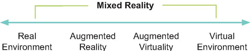
Figure 1 Reality-Virtuality Continuum adapted from [16].
Regarding Mixed Reality, there is no single definition of what it is. According to [17], it depends on the context. In this article, MR is considered the entire Reality-Virtuality Continuum, encompassing both AR and VR.
Augmented reality is not just limited to augment sight. It can also be applied to augment hearing, touching, and smelling. A definition that comprises any AR system, regardless of the sense involved, was presented by [9]. According to his definition, an AR system combines real and virtual elements in the real environment, runs interactively and in real-time, and registers real and virtual objects to each other in three dimensions. Despite AR being capable of involving several senses, AR systems that augment sight are more common in practice.
3.2 Image Compositing
Digital image compositing is a method of combining two or more source images into a final image. This combination is made by evaluating the contribution of each pixel from each original image. Let , , and be the color components of images , , and the of the composition. The Equation (1) gives the composition of images and , where and are the fractions of images and that prevail in the final composition, whose value is given according to the binary operation performed between the two source images. For the operation, for example, equals , and equals [18].
| (1) |
When blending two source images, it’s more useful to be able to select an object or subregion from image A and a subregion from image B to produce the output composite. To distinguish an arbitrary subregion in an image, we can vary the weighting function for each pixel in the image. As pointed by [19], the OpenGL provides this weighted per-pixel merge capability through the framebuffer blending operation. In framebuffer blending the weights are stored as part of the images themselves. Since the alpha values are most often used as the weights than R, G or B values, framebuffer blending is often called alpha-blending. In OpenGL, to composite a geometry against a background image, we can load the background image into the framebuffer, then render the geometry on top of it with blending enabled. So, we set the source and destination blend factors to GL_SRC_ALPHA and GL_ONE_MINUS_SRC_ALPHA, respectively, and assign 1.0 for the of the pixels corresponding to the geometry when they are sent to the OpenGL pipeline.
3.3 Ray Tracing
According to Glassner, ray tracing is an image synthesis technique whereby a 2D image of a 3D world is created [20]. Unlike rasterization, which is an object-order technique where for each object in the world, the rasterization finds and updates all the pixels influenced by it, and draws them accordingly, ray tracing is image-order rendering. Thus, a ray tracing algorithm performs an iteration over the pixels and, for each pixel, finds all the objects that influence it and computes their value.
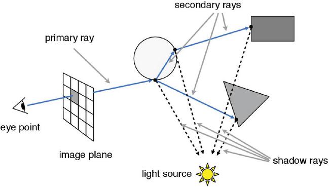
Figure 2 Recursive ray tracing schema.5
Despite having a simple logic, ray tracing algorithms have a high computational cost, which is why their use in real-time applications was impractical for many years. As pointed by [21], a basic ray tracing algorithm has three main parts: (i) ray generation, where the observer’s point of view is defined, and from which the ray will be shot towards the pixels in the scene; (ii) the computation of the ray intersections, through which the first geometry of the scene reached by the ray is obtained and secondary rays shooting; and (iii) shading, where a lighting model is used to compute the pixel color based on the result of the intersections. Algorithm 1, adapted from [22], presents the basic structure of a simple ray tracer algorithm, and Figure 2 illustrates a ray traversal.
Algorithm 1 Recursive ray tracing [22]
for each pixel (, ) do
= ray from eyepoint through pixel
image[, ] = raytrace()
end for
The ray’s origin is calculated using camera coordinates. In computer gra-phics, we can define a camera from three coordinates: (i) the eye, which determines the location where the camera is positioned; (ii) the view, or look at, direction in which it points; and (iii) the up, which determines the direction that points upwards from the camera. Let be the vector in the up direction, perpendicular to , and be the vector in the view direction. We obtain the coordinates of the origin from which the rays are shooted using the Equations (2) and (3).
| (2) | ||
| (3) |
4 The Extended Array-Tracing Middleware
We proposed the ARRay-Tracing as a middleware to integrate AR frameworks with ray tracing frameworks in a modularized way. That is, it allows users to choose which framework to use, according to their demand. This modularity is possible based on basic premises of AR frameworks and ray tracing rendering. The first, the premise that every AR system and every ray tracing system define a virtual camera with the same set of coordinates, and so, it is possible to map the coordinates of the AR framework camera to the ray tracer camera coordinates. And second, the premise that a video-based AR framework uses an image overlay to combine virtual and real elements in a scene. Therefore, it is possible to combine the final ray tracer image with the video frame obtained by the physical camera using the same technique.
The ARRay-Tracing module is responsible for two central operations: mapping the camera coordinates from the augmented reality framework to the ray tracing framework, and the image composition. The geometric reconstruction of the real environment and the lighting conditions detection of the real environment are not included in the scope of this work and, so far, are not supported by ARRay-Tracing. Figure 3 shows the extended middleware workflow, with the addition of the environment textures.
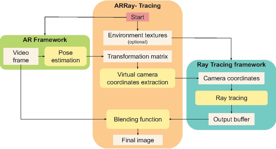
Figure 3 The ARRay-Tracing workflow.
In ARRay-Tracing middleware, the first step to integrate the two frameworks is mapping the AR camera to the ray tracing camera. Fiducial marker-based augmented reality frameworks estimate the real camera position and orientation (pose), processing the video frames to get the marker position and orientation. Frameworks based on the ARToolkit, like the ARToolkitX used in this work, give us the camera pose, in the marker’s coordinate system, by the inversion of the marker’s transformation matrix, resulting in the camera pose matrix. In this work, we used an AR framework based on fiducial markers. However, other AR frameworks can be used, as the type of marker, fiducial or natural, does not change how we extract coordinates from the camera’s transformation matrix. Let be a homogeneous matrix of the marker transformation obtained by the AR framework in the marker’s coordinate system, in a format like shown by Equation (4).
| (4) |
Sometimes, the coordinate system of the marker may not be the same as the world coordinate system in ray tracing frameworks. Figure 4 shows the marker coordinate system and the world coordinate systems for the two ray tracing frameworks covered by this work. It is possible to observe that the marker coordinate system from AR framework is the same used in the world of the Optix framework but differs from VKRay framework.
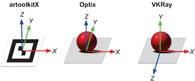
Figure 4 The coordinate systems of the marker in ARToolkitX framework, and of the world in Optix and VKRay frameworks.
As the position and orientation of the camera are defined in the ray tracing frameworks considering their world coordinates, if the coordinate systems are different, we first convert the matrix to the ray tracing framework coordinate system and then invert this matrix to get the camera pose matrix . To accomplish this, we proposed the use of predefined profiles and rotation parameters, considering that with two rotations, at maximum, the coordinate systems can be matched. When running the code, the user has the option to pass as parameter two profiles ids, one for the AR framework and one for the ray tracing framework; the first rotation degree followed by the coordinates of rotation axis; and, the second rotation degree followed by the coordinates of second rotation axis. Thus, when the user informs the rotation parameters, the middleware calculates the rotation matrix by which the camera pose matrix is multiplied. Figure 5 shows the usage help message with the explanation about the parameters. When using Optix, no conversion is required. When using the VKRay, we apply a rotation of around the x-axis passing the respective parameters “-ar 1 -rt 2 -g 90 -x 1 -y 0 -z 0” in the execution.
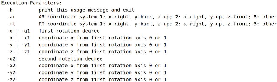
Figure 5 The usage help message explaining the profile’s parameters.
After obtaining the matrix in the ray tracing world coordinate system, by inverting this matrix we get the camera pose matrix as shown by the Equation (5).
| (5) |
From matrix, the ARRay-Tracing extracts the camera coordinates (eye, look at, and up) from AR framework, according to Equations (6), (7), and (8).
| (6) | |
| (7) | |
| (8) |
Ray tracing frameworks define their cameras using these same three coordinates eye, look at and up. Therefore, ARRay-Tracing assigns to these three variables the values extracted from matrix. Into the ray tracing framework, this values are passed to ray generation shader, which uses them to calculate the rays origin. Then, the ray traversal is performed and generates the output buffer. The ray traversal is computed and the ray generation shader writes the pixels color result in the output buffer according to the returned values by closest hit and miss shader. In this step, we assign zero to the alpha component of all pixels that did not intersect any ray, that is, we assign 0 to the fourth component of pixel color in the miss shader. This way, we get a transparent image in regions where there are no models to render.
The synchronization between the frameworks is done using a semaphore since the execution takes place in the same thread, and the framebuffer is accessed to render the image captured by the AR framework and to render the image generated by the ray tracing framework. The ray tracing framework only starts the ray tracing after the assignment of camera coordinate values, and ARRay-Tracing obtains these values after the AR framework captures and processes a video frame. Finally, the middleware only performs the image composition after the complete rendering of the framebuffer by the ray tracer.
Finally, ARRay-Tracing combines the video frame with the output image of the ray tracer through the OpenGL’s alpha blending using as blend factors GL_SRC_ALPHA and GL_ONE_MINUS_SRC_ALPHA, generating the final image to be rendered on the screen. In this process, a final image is composed by two source images, and , where is the real-world image captured by the camera, and is the virtual image generated by a ray tracing framework. This composition uses the operation, as the Equation (9), where , , and are the color components of images , , and the , and represents each image’s pixels.
| (9) |
The middleware allows modularity since any frameworks that fit the following restrictions can be used: in the AR framework, it is possible to extract the camera coordinates (eye, look at, and up) and the video frame; in the ray tracing framework, it is possible to get the output buffer with an alpha value equal to zero for pixels that do not correspond to any geometry present in the scene.
4.1 Time Complexity
The AR frameworks based on ARToolkit, like ARToolkitX, execute a detection algorithm having a complexity order of , where is the number of markers being tracked [23]. In our test scenario, we used only one marker.
A naive ray tracing implementation has a complexity order of , where and are, respectively, the width and height in pixels of the rendered image, and is the number of objects, or polygons in a scene. Modern ray tracing frameworks such as Optix and VKRay in turn use structures of type Bounding Volume Hierarchies to optimize the interceptions calculation. In this approach, instead of enclosing each object in a box, a group of objects, sufficiently close to each other, are bounded by a single box. So, the complexity order is , where is the number of boxes [24].
The ARRay-Tracing middleware integrates an AR framework and a ray tracing framework mapping the camera coordinates and performing an image composition. The camera mapping is an operation where the coordinates are extracted from the camera pose matrix according to Equations (6), (7), and (8), and assigned to their corresponding variables in ray tracing framework. So, this operation has a complexity order of . The image composition consists of, for each pixel of the image, performing a linear combination of the values of two source pixels. So, this operation has a complexity order of , where is the width and is the height in pixels of the rendered image. Therefore, the ARRay-Tracing middleware has the complexity order of the image composition, that is, . Thus, as expected, the ray tracing framework have dominance in complexity order.
5 Results
To test our middleware we chose ARToolkitX as the AR framework because it is a continuation of the classic ARToolkit, and which works very well with fiducial markers. Optix was identified as a possible ray tracing framework for use in our application through a review of photorealism trends in Mixed Reality [5]. Like ARToolkitX, it works with the OpenGL graphical API,6 which would facilitate the integration process. The VKRay, in turn, works with the Vulkan graphical API.7 However, it is possible to establish interoperability between this framework and the OpenGL by using specific extensions. Therefore, we chose to switch between two modern real-time ray tracing frameworks to test the modularity of our middleware.
The implementation is similar for both versions. We mapped the camera coordinates extracted via the ARToolkitX to the camera’s coordinates of the Optix and the VKRay. We then performed ray tracing on each of framework according to the examples available in each SDK. For the final composition of the images, we used the OpenGL’s alpha blending in both versions because the ARToolkitX and the Optix render the final image through it and, with the interoperability extension, we were able to create a texture in the OpenGL from the VKRay’s output buffer.
We performed the tests on a desktop with an AMD Ryzen 5 3600 processor; 16GB DDDR4 3600Mhz RAM; GTX 1060 6Gb, graphic driver version 455.46.04; Microsoft LifeCam Cinema webcam, and Ubuntu 18.04.5 LTS operating system.
5.1 Qualitative Analysis
For the tests, we selected some models from the Stanford repository to be visualized with different materials: Stanford Bunny, Lucy, Dragon, and Happy Buddha.8 We also used the Utah Teapot model, and built a scene using cuboids and a sphere. Table 1 shows the number of faces of the models used. We only used materials and shaders available in the examples and tutorials of the two SDKs, therefore we did not compare the visual results obtained in the two versions of the application since the visual results are different.
Table 1 Face counting of the models used
| Model | Faces |
| Bunny | 4.968 |
| Utah Teapot | 126.048 |
| Lucy | 448.880 |
| Dragon | 871.306 |
| Happy Buddha | 1.087.451 |
The complexity of rendered scenes depends on the computational cost of shading for each material type and is proportional to the number of pixels the geometry occupies in the render window. Shine materials have a low computational cost in shading, while reflective or refractive materials have a higher computational cost. We initially rendered less complex scenes in both frameworks to assess whether a satisfactory frame rate for real-time, around 30 fps, was achieved. Later, only for the Optix framework, scenes of greater complexity were generated to evaluate the interaction between real and virtual elements, without the obligation to obtain a frame rate greater than or equal to 30 fps.
The initial scenes, shown in Figures 6 and 7, were rendered in an 800600 pixels window. In the closest hit shader, the alpha value of 1.0 was assigned to all pixels that had some intersection and matched some geometry. Therefore, during the image composition step, the framebuffer generated by the ray tracer had only two alpha values, equal to 1.0, for the pixels with the virtual elements’ geometry, and an alpha equal to 0, assigned in the miss shader, for the pixels that did not correspond to any geometry.
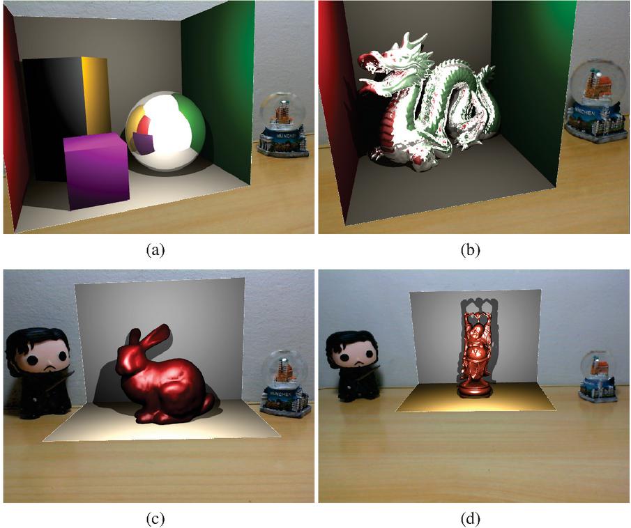
Figure 6 VKRay tests. In (a) Cuboids and sphere, (b) Dragon model, (c) Bunny and (d) Happy Buddah.
Figure 6 shows four scenes rendered using VKRay. In all VKRay scenes, lighting is provided by a point light source with varying intensity and white color. For the scene in Figures 6.a and 6.b, the diffuse material was used for cuboids and the surroundings, which simulates a Cornell box, while a reflective material was used for the sphere and the Dragon model. In the sphere, it is possible to see the reflection of the surrounding virtual elements and the reflection of a white area that corresponds to the background color of the empty part of the world. On the Dragon model, we can also observe the reflection of the surrounding virtual surfaces and the white area corresponding to the empty part of the world, just like in the sphere from Figure 6.a. It is important to emphasize that the Cornell box was inserted in these scenes so that the reflection of the surrounding virtual elements could be perceived, since in these examples there is no interaction between real and virtual elements.
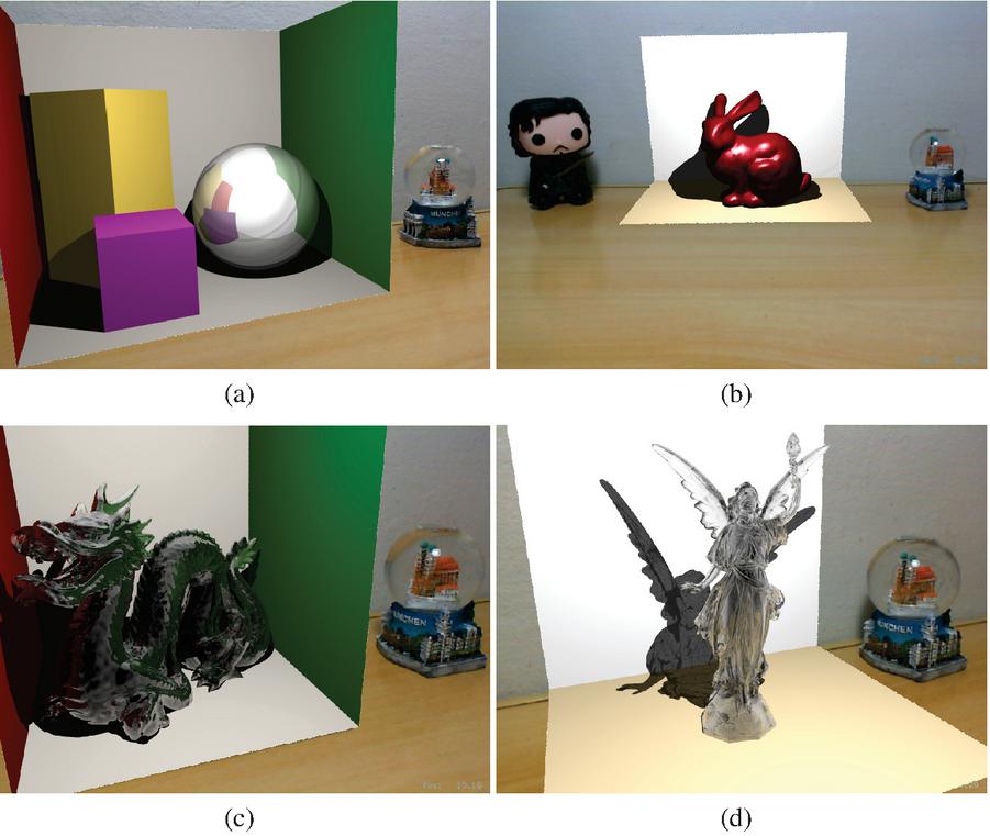
Figure 7 Optix preliminary tests. In (a) Cuboids and sphere, (b) Bunny, (c) Dragon and (d) Lucy. Figures (c) and (d) were rendered using materials which simulate glass.
For the scene in Figures 6.c and 6.d, we placed two planes to simulate the geometry of the real environment and enable the visualization of shadows. In both planes, diffuse material was used. For the Bunny and Happy Buddha model, specular materials were used. Considering that in VKRay, the point light was positioned to approximate the real lighting position, in 6.c, it is possible to notice that shadows were cast in similar directions for the Bunny and the Jon Snow real toy figure.
The scenes using Optix were created based on the examples available on the framework’s SDK. Diffuse, specular, reflective and glass materials were extracted from these examples. Figure 7 show four scenes rendered using Optix. In Figure 7.a, a diffuse material was used in the planes forming the Cornell box and also in the cuboids. The sphere was rendered using a reflexive material, and it is possible to see reflected on its surface the surrounding elements, including the empty world in white. In Figure 7.b, the Bunny model was rendered using a specular material. The planes replicating the real wall and table were rendered using a diffuse material.
The Dragon and the Lucy models in Figure 7.c and 7.d were rendered using solid glass materials. The Dragon is a denser model and consequently, it is not possible to visualize the refraction in most of its body. It can only be seen in the less dense parts, such as the horns. The reflection, in turn, is noticeable throughout the entire length of the Lucy model, facilitating the visualization of refraction, especially in the wings. Lucy is a less dense model using solid glass material, so shadows cast by the model is lighter than the shadows cast by solid material models.
5.2 Blending Real and Virtual Objects
When blending real and virtual objects using ray tracing into an augmented reality application, reflective and refractive materials become a challenge. In order to obtain a photorealistic visualization on the surfaces of objects made of reflective materials, we must be able to see the reflection of real objects around them. For refractive objects, we must perceive the elements behind them through their surface.
In order to be able to perceive the interaction between real and virtual elements, it is necessary to replicate, at some level, the real environment in the virtual environment. In this work, we proposed to insert a textured box in the virtual world whose surfaces were textured with images of the real environment. Thus, the proposed solution applies to a controlled environment, where the positioning of the real elements and the images of the environment are previously known. The box was a cube measuring 220 mm on each face, positioned around the geometry of interest. Each face was textured with a previously captured image of the environment (Figure 8).
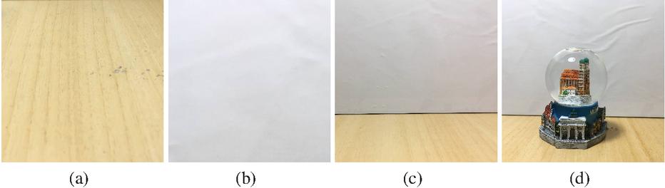
Figure 8 Textures used in the box composed by the floor (a), ceiling (b), empty side walls (c), and snow globe in front a wall (d).
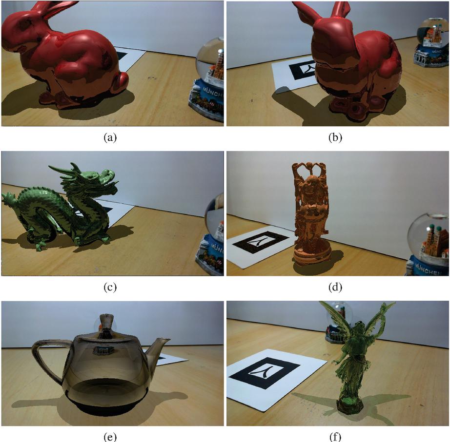
Figure 9 Final images with an improved blending between virtual objects and the environment. We rendered the Bunny model in (a) and (b), Dragon (c), Happy Buddah (d), Utah teapot (e) and Lucy (f).
Using the Optix framework, we applied this solution to render the scenes shown in Figure 9. The scenes were rendered in a window of 1280 720 pixels. To obtain only the virtual geometry of interest in the final image, we used the any hit shader to check if the pixel represented a shadow region on a textured box’s area during the ray traversal. If so, we assign an alpha value between 0 and 1 to that pixel. For the remaining pixels of the textured box, corresponding to a region not being shadowed by other geometry, we assigned a value of 0 to alpha in the closest hit shader. For pixels referring to the geometry of interest an alpha equals to 1 was assigned. Thus, in the framebuffer generated by the ray tracer, three distinct alpha values were presented, the value 0 for pixels that did not correspond to the geometry of interest, nor the shadow region; a value between 0 and 1 for pixels that matched a shadow region, we used 0.6 for opaque geometry shadow and 0.3 for translucent geometry shadow; and the value 1 for pixels corresponding to the geometry of interest.
In Figure 9.a the Bunny model was rendered with a reflexive material and it is possible to see the snow globe reflected in it’s surface. Figure 9.b shows the same model in another point of view. Figure 9.c the Dragon model was rendered with a reflexive material. Since it does not have a smooth surface, we see a blurred reflected snow globe on it’s surface, mainly a blue region. Figure 9.d shows the Happy Buddah model rendered with a reflective surface. The reflection of the snow globe can be perceived by small blue areas along its surface. Figure 9.e the Utah teapot model was rendered with a glass material. In the scene we can see the snow globe texture through the teapot body. Finally, in Figure 9.e, the Lucy model was rendered with a glass material. It is possible to perceive the refraction of the snow globe through the colors in Lucy’s left wing.
6 Quantitative Analysis
We observed that using the ARRay-Tracing, the maximum frame rate was 30 fps for all scenes. This maximum value is due to the limitation in the camera’s capture capacity. For the pixel format used by ARToolkitX, the camera we used in the tests captures a maximum of 30 fps. Some scenes that rendered more complex models with specific materials of bigger computational cost calculation, like the reflective material in VKRay or the glass material in Optix, had a higher frame rate when the camera was away from the object, decreasing as the camera approached the object, as expected, since the number of intersections calculations increases as the camera moves closer to the models and the amount of detail increases.
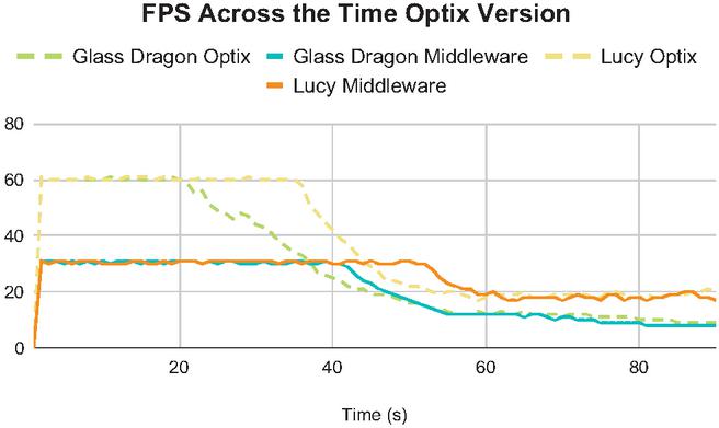
Figure 10 Frame rate across the time Optix version.
In order to verify with practical examples that the impacts of the camera capture limitation is lower than ray tracing when rendering more complex scenes, we tested bringing the camera closer to the marker and recording the frame rate during this approximation. In these tests, we initially recorded the camera’s position and orientation using the ARRay-Tracing version considering one record per frame, and then consumed this data using Optix and VKRay versions to repeat the same camera movement.
Figure 10 shows that the application with pure Optix initially reaches a higher frame rate, around 60 fps, while ARRay-Tracing is limited to 30 fps for both scenes. As the camera approaches the rendered model, the frame rate drops in both versions and starts to tend towards the same value for each scene.
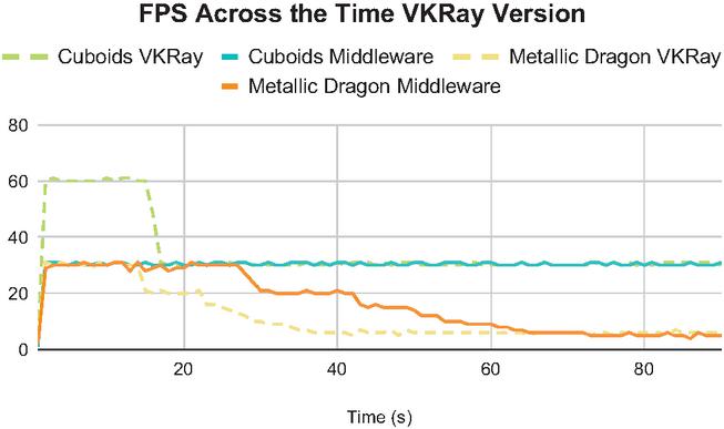
Figure 11 Frame rate across the time VKRay version.
In Figure 11, two slightly different scenarios are shown. In the first scene, the cuboids, the frame rate starts higher on VKRay, around 60 fps, while the ARRay-Tracing is limited to 30, as a result of the limitation of the camera that captures at most 30 frames per second. However, being a less computationally costly rendering scene, the frame rate with the camera near the models is still relatively high, staying close to 30 fps in VKRay and holding constant in ARRay-Tracing. In the second scene, the metallic dragon, as it is computationally more expensive, the frame rate is already limited to 30 fps for both VKRay and ARRay-Tracing. As the camera approaches the model, the frame rate similarly decreases and converges to the same value for both cases.
7 Conclusion
In this work, we proposed an extended version of the ARRay-Tracing, a middleware to integrate augmented reality and ray tracing frameworks in a modularized way. As the middleware works with camera mapping and image composition, any framework can be used with it as long as, for AR, it is possible to obtain the camera’s coordinates: eye, look at, and up; and for ray tracing, it is possible to manipulate the image generated by the method execution.
We also present an evaluation of middleware using two different ray tracing frameworks, Optix and VKRay, integrated with the ARToolkitX augmented reality framework. We could conclude that ARRay-Tracing does not add processing overhead to the application through the evaluation comparing the use of middleware to the use of only ray tracing frameworks, in Figures 10 and 11, as was expected since ray tracing has the biggest complexity order in the whole process. The frame rate values obtained are inversely proportional to the complexity of the rendered models and materials. Due to the camera used and the ARToolkitX settings in the test environment, we identified the 30 fps limit for applications using the middleware. This maximum value is likewise obtained in applications using only the AR framework and is also considered the threshold to classify an application as real-time.
Through this work, we achieved photorealistic visual effects in AR applications using the ARRay-Tracing middleware for controlled environment applications, where it is possible to simulate the real environment through a box built using real images as textures. For more complex scenes where the frame rate is less than 10 fps, AR’s real-time interactivity principle is violated. Therefore, integration is satisfactory only in applications with less complex geometries and materials. Also, ARRay-Tracing did not include methods for reconstructing the geometry and lighting of the real environment, thus, geometry positioning and lightning conditions are arbitrarily defined. Consequently, real and virtual elements seem visually different, and there is no proper occlusion between them. Many AR applications are developed for the mobile platform, but since real-time ray tracing is unfeasible in this platform, ARRay-Tracing was proposed for desktop-based applications.
As future work, it would be interesting to add the integration with methods to reconstruct geometry and lightning of the physical environment to the middleware. This way, it would be possible to recreate the same lighting conditions in ray tracing frameworks, and the virtual models would be visually more similar to real objects.
Footnotes
*This study was financed in part by the Coordenação de Aperfeiçoamento de Pessoal de Nível Superior – Brasil (CAPES) – Finance Code 001
1https://developer.nvidia.com/optix; accessed on 04/01/2022
2https://developer.nvidia.com/blog/whats-new-in-nvidia-vkray/; accessed on 04/01/2022
3http://www.ARToolkitX.org/; accessed on 04/01/2022
4https://cs184.eecs.berkeley.edu/sp18/lecture/ray-intro; accessed on 04/01/2022
5https://www.opengl.org/; accessed on 04/01/2022
6https://www.vulkan.org/; accessed on 04/01/2022
7http://graphics.stanford.edu/data/3Dscanrep/; accessed on 04/01/2022
References
[1] Ronald T. Azuma, Yohan Baillot, Reinhold Behringer, Steven K. Feiner, Simon Julier, and Blair MacIntyre. Recent advances in augmented reality. IEEE Computer Graphics and Applications, 21(6):34–47, 2001.
[2] Kangsoo Kim, Mark Billinghurst, Gerd Bruder, Henry Been-Lirn Duh, and Gregory F. Welch. Revisiting trends in augmented reality research: A review of the 2nd decade of ismar (2008–2017). IEEE Transactions on Visualization and Computer Graphics, 24(11):2947–2962, 2018.
[3] Insu Yu, Jesper Mortensen, Pankaj Khanna, Bernhard Spanlang, and Mel Slater. Visual realism enhances realistic response in an immersive virtual environment – part 2. IEEE Computer Graphics and Applications, 32(6):36–45, 2012.
[4] Cha Lee, Gustavo A. Rincon, Greg Meyer, Tobias Höllerer, and Doug A. Bowman. The effects of visual realism on search tasks in mixed reality simulation. IEEE Transactions on Visualization and Computer Graphics, 19(4):547–556, 2013.
[5] Lidiane Teixeira Pereira, Wellingston Cataldo Roberti Junior, and Rodrigo Luis de Souza da Silva. Photorealism in mixed reality: A systematic literature review. International Journal of Virtual Reality, 21(1):15–29, 2021.
[6] Aleksander Yacovenco and Rodrigo Luis de Souza da Silva. Towards photorealism in augmented reality–a brief review on the main requirements. Relatórios Técnicos do DCC/UFJF, 2022.
[7] Alexander. Keller, Luca Fascione, M. Fajardo, Iliyan Georgiev, Per H. Christensen, Johannes Hanika, Christian Eisenacher, and Greg Boyd Nichols. The path tracing revolution in the movie industry. In ACM SIGGRAPH 2015 Courses, SIGGRAPH ’15, New York, NY, USA, 2015. Association for Computing Machinery.
[8] Alexander Keller, Timo Viitanen, Colin Barré-Brisebois, Christoph Schied, and Morgan McGuire. Are we done with ray tracing? In ACM SIGGRAPH 2019 Courses, SIGGRAPH ’19, New York, NY, USA, 2019. Association for Computing Machinery.
[9] Ronald T. Azuma. A Survey of Augmented Reality. Presence: Teleoperators and Virtual Environments, 6(4):355–385, 08 1997.
[10] Lidiane Teixeira Pereira, Wellingston Cataldo Junior, Jairo Francisco de Souza, and Rodrigo Luis de Souza da Silva. Array-tracing-a middleware to provide ray tracing capabilities to augmented reality libraries. In 2020 22nd Symposium on Virtual and Augmented Reality (SVR), pages 391–397. IEEE, 2020.
[11] Artur Lira dos Santos, Diego Lemos, Jorge Eduardo Falcão Lindoso, and Veronica Teichrieb. Real time ray tracing for augmented reality. In 2012 14th Symposium on Virtual and Augmented Reality, pages 131–140. IEEE, 2012.
[12] Peter Kán and Hannes Kaufmann. Differential irradiance caching for fast high-quality light transport between virtual and real worlds. In 2013 IEEE International Symposium on Mixed and Augmented Reality (ISMAR), pages 133–141. IEEE, 2013.
[13] Tobias Schwandt and Wolfgang Broll. A single camera image based approach for glossy reflections in mixed reality applications. In 2016 IEEE International Symposium on Mixed and Augmented Reality (ISMAR), pages 37–43. IEEE, 2016.
[14] Christian Vazquez, Nicole Tan, and Shrenik Sadalgi. Fused photo: Augmented reality staging for photorealistic visualization in online home retail. In Extended Abstracts of the 2021 CHI Conference on Human Factors in Computing Systems, pages 1–7, 2021.
[15] A’aeshah Alhakamy and Mihran Tuceryan. Cubemap360: Interactive global illumination for augmented reality in dynamic environment. In 2019 SoutheastCon, pages 1–8, 2019.
[16] Paul Milgram and Fumio Kishino. A taxonomy of mixed reality visual displays. IEICE TRANSACTIONS on Information and Systems, 77(12):1321–1329, 1994.
[17] Maximilian Speicher, Brian D Hall, and Michael Nebeling. What is mixed reality? In Proceedings of the 2019 CHI conference on human factors in computing systems, pages 1–15, 2019.
[18] Thomas Porter and Tom Duff. Compositing digital images. In Proceedings of the 11th Annual Conference on Computer Graphics and Interactive Techniques, SIGGRAPH ’84, page 253–259, New York, NY, USA, 1984. Association for Computing Machinery.
[19] Tom McReynolds and David Blythe. Advanced graphics programming using OpenGL. Elsevier, 2005.
[20] Andrew S Glassner. An introduction to ray tracing. Morgan Kaufmann, 1989.
[21] Steve Marschner and Peter Shirley. Fundamentals of computer graphics. CRC Press, 2018.
[22] John F Hughes, Andries Van Dam, Morgan McGuire, James D Foley, David Sklar, Steven K Feiner, and Kurt Akeley. Computer graphics: principles and practice. Pearson Education, 2014.
[23] Wnêiton Gomes, Celso Camilo, Leonardo Lima, Alexandre Cardoso, Edgard Lamounier Jr, and Keiji Yamanaka. Artificial neural networks to recognize artoolkit markers. In International Conference on Artificial Intelligence and Pattern Recognition, pages 464–469, 01 2007.
[24] Héctor Antonio Villa Martınez. Accelerating algorithms for ray tracing. Technical report, Department of Computer Science, University of Sonora, 2006.
Biographies

Lidiane Teixeira Pereira holds a Master’s degree in Computer Science from the Federal University of Juiz de Fora, the same institution where she received her Bachelor’s degree in Computer Science. Throughout her undergraduate and master’s degrees, she participated in research projects on Virtual and Augmented Reality.
Jairo Francisco de Souza holds a Ph.D. (2012) in Informatics from the Pontifical Catholic University of Rio de Janeiro, Brazil. Jairo Souza is a full professor in Information Retrieval and Natural Language Processing, member of LApIC research group at Federal University of Juiz de Fora, Brazil. He has worked on several research projects funded by the Brazilian National Research and Educational Network (RNP), Coordination for the Improvement of Higher Education Personnel (CAPES), National Council for Scientific and Technological Development (CNPq), and others. His research interests are knowledge representation, semantic web, information integration, and natural language processing.

Rodrigo Luis de Souza da Silva is an Associate Professor in the Department of Computer Science at Federal University of Juiz de Fora. He has a B.S. in Computer Science from the Catholic University of Petropolis (1999), M.S. in Computer Science from Federal University of Rio de Janeiro (2002), Ph.D. in Civil Engineering from Federal University of Rio de Janeiro (2006) and a postdoc in Computer Science from the National Laboratory for Scientific Computing (2008). His main research interests are Augmented Reality, Virtual Reality, Scientific Visualization and Computer Graphics.
Journal of Mobile Multimedia, Vol. 18_6, 1633–1658.
doi: 10.13052/jmm1550-4646.1868
© 2022 River Publishers