Range and Capacity Considerations for Terahertz-Systems for 6G Mobile and Wireless Communication
Werner Mohr
Consultant, Lecturer at Technical University Berlin, Germany
E-mail: mohr_werner@t-online.de
Received 30 April 2022; Accepted 31 May 2022; Publication 20 September 2022
Abstract
Discussions on research directions towards systems beyond 5G/6G have started. One of the potential elements of future mobile and wireless systems are new radio systems in the (sub)-Terahertz domain above 100 GHz for communication and sensing purposes. This paper is investigating potentially available frequency bands based on the ITU Radio Regulation, basic propagation conditions above 100 GHz including the different additional path loss contributions on top of distance dependent path loss such as atmospheric and rain attenuation, foliage and wall penetration loss. The impact on system performance like range and channel capacity is considered under idealized conditions at Shannon limit and demonstrated by indoor and outdoor, uplink and downlink scenarios. Radiation limits based on internationally accepted regulations are taken into account in scenarios, where humans are directly involved in the communication. In other scenarios less stringent requirements apply. The main purpose of this paper is to get an understanding from a system perspective of the relation between achievable data throughput versus range and system bandwidth for different propagation conditions and carrier frequency ranges and to investigate basic physical limits. This understanding helps in the identification of use cases, applications and economic considerations on system deployment.
Keywords: Sub-Terahertz radio systems, frequency bands, radio propagation, radiation limits, system capacity versus range, sensing applications.
1 Introduction
In the scientific and industrial research community research activities have started to investigate the further development of systems beyond 5G or 6G. Part of this discussion is the exploration of new frequency bands in the sub-Terahertz domain above 100 GHz for mobile and wireless communication. Potential technical KPIs for such systems are currently under discussion mainly in the scientific community with respect to the envisaged usage of future systems, cost implications, business cases and technical feasibility. For the time being no KPIs (Key Performance Indicator) are globally agreed for the evolution of current communication systems towards 6G. The EU EMPOWER project developed a first proposal of radio-related KPIs for future systems [1], which are also used in the Networld2020 Strategic Research and Innovation Agenda [2]. The envisaged frequency spectrum is considered in several steps 250 GHz, 500 GHz and 1000 GHz with carrier bandwidth between 0.5 to 10 GHz and associated very high peak and user data rates significantly exceeding today’s systems. It is expected that such wide frequency bands could be made available in the sub-Terahertz frequency range. These examples in [1] present a suggestion for network KPIs for the short-, medium- and long-term evolution of 5G. Such KPIs are under investigation and need to fit to requirements of industry and will be regularly updated based on state-of-the art findings. ITU-R WP5D (International Telecommunication Union, Radio Sector, Working Party 5D) started in February 2020 a “Technology Trend Report”, which should lead to an update of the “IMT Visions” Recommendation for systems beyond 5G including globally accepted technical KPIs [3]. WP5D started the work on the revised IMT Vision Recommendation in June 2021 which should be finalized and approved prior to WRC 2023 (World Radiocommunications Conference).
2 Potential Frequency Bands
The currently available ITU-R Radio Regulation [4] from 2020 is limited to frequency bands up to 275 GHz. The potential availability of bands below 275 GHz needs to be checked with [4] in Vol I. In the frequency range from 100 GHz to 275 GHz the following bands have a mobile allocation in all regions with certain restrictions besides allocations also to other services: 102–105 GHz, 105–109.5 GHz, 111.8–114.25 GHz, 122.25–123 GHz, 130–134 GHz, 141–148.5 GHz, 151.5–155.5 GHz, 155.5–158.5 GHz, 158.5–164 GHz, 167–174.5 GHz, 174.5–174.8 GHz, 191.8–200 GHz, 209–217 GHz, 217–226 GHz, 231.5–232 GHz, 232–235 GHz, 238–240 GHz, 240–241 GHz, 252–265 GHz and 265–275 GHz. Therefore, these bands cannot be regarded as directly available for mobile and wireless applications. Resonance and absorption effects of atmospheric attenuation at 120 GHz and 184 GHz (c.f. Section 3.4) are avoided for mobile allocations.
According to [4, Vol I, p. 185] there is currently no allocation in the frequency range 275 to 3000 GHz. However, the footnote 5.564A in [4, Vol I, p. 185] opens options for land mobile and fixed service applications for the following bands: 275–296 GHz, 306–313 GHz, 318–333 GHz and 356–450 GHz. The absorption/resonance peaks of atmospheric attenuation at 324 GHz in the band 318–333 GHz and at 380 GHz in the band 356–450 GHz do not allow the full use of these bands. According to footnote 5.564A the additional bands “296–306 GHz, 313–318 GHz and 333–356 GHz may only be used by fixed and land mobile service applications when specific conditions to ensure the protection of Earth exploration-satellite service (passive) applications are determined”.
On the other hand, according to footnote 5.565 in [1, Vol I, p. 186] several scattered bands are identified for passive service applications (Figure 1), where an opening is also given for active services such as mobile communications:
• Radio astronomy service: 275–323 GHz, 327–371 GHz, 388–424 GHz, 426–442 GHz, 453–510 GHz, 623–711 GHz, 795–909 GHz and 926–945 GHz;
• Earth exploration-satellite service (passive) and space research service (passive): 275–286 GHz, 296–306 GHz, 313–356 GHz, 361–365 GHz, 369–392 GHz, 397–399 GHz, 409–411 GHz, 416–434 GHz, 439–467 GHz, 477–502 GHz, 523–527 GHz, 538–581 GHz, 611–630 GHz, 634–654 GHz, 657–692 GHz, 713–718 GHz, 729–733 GHz, 750–754 GHz, 771–776 GHz, 823–846 GHz, 850–854 GHz, 857–862 GHz, 866–882 GHz, 905–928 GHz, 951–956 GHz, 968–973 GHz and 985–990 GHz.
With respect to Figure 1 only parts of the upper sub-Terahertz domain 500 GHz (white parts without radio astronomy, earth exploration and space research) can potentially be used as consecutive bands for communication purposes: 510–523 GHz, 527–538 GHz, 581–611 GHz, 711–713 GHz, 718–729 GHz, 733–750 GHz, 754–771 GHz, 776–795 GHz, 945–951 GHz, 956–968 GHz, 973–985 GHz and 990–1000 GHz.
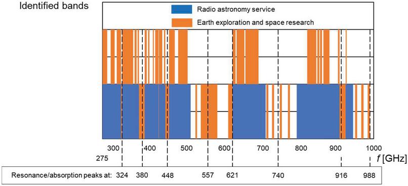
Figure 1 Identified bands in the frequency range 275–1000 GHz including resonance/absorption peaks of atmospheric attenuation (c.f. Section 3.4).
According to [5] the bands 116–123 GHz, 174.8–182 GHz, 185–190 GHz and 244–246 GHz are proposed by FCC as unlicensed spectrum [6], which is different from [4].
3 Propagation Conditions
3.1 Near- and Far-field Considerations
In the sub-Terahertz domain, the wavelength is very small. At exemplary frequency ranges outside of resonance/absorption effects of atmospheric attenuation corresponds to
• 0.1224 cm at 245 GHz,
• 0.0563 cm at 515 GHz and
• 0.0385 cm at 780 GHz.
The distance r between the mobile device transmitter and humans as well as the expected achievable range are short. Therefore, near-field (Rayleigh distance r) and far field (Fraunhofer region r r) conditions need to be considered with [7, p. 302] and [8, p. N2], which are related to the maximum general aperture size D of the transmit antenna, the wavelength and the distance r:
| (1) | ||
| (2) |
The transition between both regions is the Fresnel Region r for . With increasing antenna gain and also decreasing wavelength the near- and far-field regions are increasing significantly.
Handheld devices are used very close to the human head with distances in the order of a few cm. Such devices are usually using antennas with low gain with a maximum aperture size of D (5 assumed). Tablets and laptop type devices are used with a wider distance of 30 to 50 cm with higher gain antennas. Here an aperture size of 20 is assumed (Table 1).
Table 1 Near- and far-field conditions for handheld devices, tablets and laptops
| Handheld, D 5 | Tablet, Laptop, D 20 | |||||
| f [GHz] | 245 | 515 | 780 | 245 | 515 | 780 |
| Near-field r [cm] | 0.85 | 0.40 | 0.27 | 6.79 | 3.23 | 2.13 |
| Far-field r [cm] | 6.12 | 2.91 | 1.92 | 97.92 | 46.64 | 30.80 |
It is expected that sub-Terahertz radio systems are mainly used for point-to-point connections. Therefore, depending on the used frequency band a handheld device with D 5 would be operated in the far-field and a tablet or laptop with D 20 in the Fresnel region with the minimum assumed distance r 10 cm (c.f. Section 4). If also the tablet and laptop should be operated under far-field conditions the maximum antenna size is limited to D 6.39 0.782 cm at 245 GHz to D 11.4 0.439 cm at 780 GHz.
At the base station/access point an antenna size (assumption parabolic antenna) with diameter D 0.3 m is assumed in the following. The near- and far-field conditions are summarized in Table 2 as well as the ideal antenna gain G with efficiency . This aperture size is electrically very big compared to . Therefore, the far-field from the base station/access point will only be reached at long distance r. In most cases, the downlink is operated in the Fresnel Region. In the near-field and Fresnel region the transmit antenna does not appear at the receiver location as a point source and the effective base station antenna gain is smaller than under far-field conditions. However, in the following all range calculations are done under the assumption of far-field conditions as best-case.
Table 2 Near- and far-field conditions for base station/access point
| Base Station/Access Point, | |||
| D 0.3 m | |||
| f [GHz] | 245 | 515 | 780 |
| Near-field r [m] | 2.91 | 4.29 | 5.19 |
| Far-field r [m] | 147.0 | 309.0 | 468.0 |
| G [dB] | 57.7 | 64.5 | 67.8 |
3.2 Fresnel Zone
According to [9, p. 97] the nearly undisturbed line-of-sight (LOS) propagation is ensured, if the first Fresnel zone k 1 is free of obstacles. The Fresnel-ellipsoid k is defined, if the difference between the direct path and the path along this ellipsoid has a difference k/2. Obstacles may approach the direct line as close as R with the path length r between transmitter and obstacle location and r between the obstacle location and the receiver
| (3) |
At 245 GHz and r r 100 m the radius of the first ellipsoid R results in 0.247 m. That means that obstacles can be very close to the direct propagation path. With reduced distance r the radius R is decreasing and with increasing frequency f also decreasing.
3.3 Path Loss and Free Space Propagation
Shadowing results in statistical fluctuations of the received power according to a log-normal distribution and thereby in a significantly higher path loss L versus radio range r compared to free space propagation [10, p. 104]. These fluctuations correspond to slow fading along the propagation path with a correlation length related to the size of, e.g., buildings (). r is a reference distance, n corresponds to the path loss coefficient depending on the environment and X to a zero mean Gaussian process in [dB] with standard deviation .
| (4) |
Due to the high overall path loss in the sub-Terahertz domain only free space or line-of-sight (LOS) propagation scenarios with L are assumed as best-case and the impact of multipath propagation according to, e.g., a Rayleigh or Rice distribution is not considered.
| (5) |
Under these best-case conditions, no fading margin and outage probability at cell border are taken into account in link-budget calculations. The assumed free first Fresnel zone (Section 3.2) justifies the approach of free space propagation. The propagation behavior at millimeter wave frequencies is described, e.g., in [11] to [16]. In addition to free space propagation in Equation (5) other attenuation components have to be considered in the sub-Terahertz domain:
• atmospheric path loss due to water vapor, oxygen, other gases L,
• rain (and mist and fog) attenuation L,
• foliage attenuation L and
• wall penetration loss (not considered, because indoor-to-outdoor penetration is not feasible without repeaters in the sub-Terahertz domain).
with the overall path loss in [dB] for outdoor applications with the first three components:
| (6) |
In indoor scenarios it is assumed that no attenuation due to rain and foliage is considered. Only the additional atmospheric attenuation plays a role. In air-conditioned rooms a lower atmospheric attenuation may be achieved by reducing the humidity.
| (7) |
3.4 Atmospheric Path Loss
With increasing carrier frequency atmospheric attenuation is increasing too. Above 20 GHz at specific frequencies resonance/absorption effects of certain gases (water vapor HO and Oxygen O) in the atmosphere increase the attenuation [5], [8, pp. H12 and H30], [17, 18] and [19]. The actual attenuation values in [dB/km] increase with humidity. Above the resonance(absorption peak at 324 GHz the attenuation is above 10 dB/km and above 450 GHz the attenuation is above 100 dB/km for higher humidity. Selected parameters L for the system capacity versus range calculations are summarized in Table 3.
3.5 Rain Attenuation
Climatic impacts such as high humidity, rain and snow result in additional slowly time varying attenuation. The additional rain attenuation L can be calculated according to CCIR-recommendation [17, pp. 91], [20] and [21, pp. 2–68]:
| (8) |
r corresponds to the distance between the antennas in [km] and R to the rain rate in [mm/h], which happens in more than p 0.01% of all cases within a year. a and b are frequency dependent and provided between 1 to 400 GHz for horizontal and vertical polarization in [20] and [21, pp. 2–70]. For changing rain probabilities p in the range 0.001% p 1 % the additional attenuation can be scaled as:
| (9) |
The rain intensity depends on the region in the world, which is subdivided into 5 regions [17, Figure 12]. In the following it is assumed to use an expected rain intensity, which is exceeded in more than p 0.001 % (corresponding to 5 nines availability) of all cases within a year. At higher frequencies rain attenuation has a significant impact for outdoor propagation, which could be bigger than the atmospheric attenuation. Above about 100 GHz the rain attenuation is becoming rather flat with a plateau with an attenuation of a few percent below the maximum [22, 23] and [24]. Values for rain attenuation are selected for p 0.001 % for high reliable links at 245, 515 and 780 GHz for regions 1, 3 and 5 (Table 3).
3.6 Foliage Loss
Foliage provides a significant attenuation at millimeter wave and sub-Terahertz frequency ranges. The empirical model as developed by CCIR Rpt 236-2 shows the relation between the frequency f in [MHz] within 200 MHz f 95000 MHz, the depth of foliage transversed in [m] with m [25].
| (10) |
It can be expected that this attenuation is not decreasing beyond 95 GHz. The evaluation of Equation (10) shows a significant impact of foliage on the additional path loss. Therefore, propagation through vegetation should be avoided, because the link will be interrupted except for very short distance 5 m. In the following no foliage is taken into account.
3.7 Link Budget
With respect to the high overall path loss only LOS scenarios are considered. In the simplified link budget for the minimum necessary received power P, no diversity gain, handover gain, fading margin and co-channel interference margin, foliage and wall penetration loss are taken into account. A realization loss M (cable losses between antennas and transmitter and receiver, losses due to diplexers/switches/filters, de-adjustment of antennas, non-ideal synchronization, altering etc.) is added. P follows with the transmit power P, the gain of transmit antenna G, receive antenna G and the distance r. It can also be expressed by the minimum necessary signal/noise-ratio S/N, the thermal noise power density N, receiver noise figure F [8, p. Q9]. and system bandwidth W:
| (11) |
It depends on the carrier frequency and the distance, which path loss component L, L and L is dominating the overall path loss. For short range the contribution from the Friis formula in Equation (5) is dominating for the investigated frequency range. With increasing frequency, the impact of atmospheric attenuation is growing, where the impact of rain attenuation is in between. The product of transmit power P and transmitter antenna gain G can be replaced by the Equivalent Isotropic Radiated Power . The base station and mobile terminal antenna aperture size depend on the formfactor of these devices. Parabolic antennas with a diameter of d 0.02 m (tablet), 0.1 m (laptop) and 0.3 m (base station) are selected in the following. In the sub-Terahertz domain this results in high antenna gain and high directivity with very narrow beam-width [8, pp. N8].
4 Radiation Limits
In application scenarios, where human beings are directly involved, limits of radiated electromagnetic power need to be respected. In the frequency range 2 GHz f 300 GHz the radiation limits of electromagnetic power are given as [26] (no additional safety factors):
| (12) |
In the following it is assumed that these limits also apply in the sub-Terahertz frequency range up to 1000 GHz. The reference distance r is selected as
• end devices (tablets and laptops) used very closely by humans: r 0.1 m
• access points or base stations: r 1.0 m.
Due to the small wavelength in the sub-Terahertz domain and with increasing antenna gain users at the reference distance are operated in the near-field or Fresnel region (Section 3.1). According to [26] the same radiation limits can be assumed in this region as in the far-field. As worst-case assumption Equation (12) is regarded valid also under near-field conditions, because the effective near-field antenna gain is smaller than the far-field antenna gain. With the radiation limit in Equation (12) the maximum allowed EIRP follows at the reference distance:
| (13) |
• end device:
• access point / base station: .
If several transmitters are close to humans, the aggregated radiation density is relevant.
5 Link Capacity Versus Range
Under idealized conditions as described above the minimum received power P provides the maximum possible Shannon channel capacity C [27, pp. 568], where co-channel interference is not considered. In this sense C is interpreted as the peak data rate of the radio system in a noise limited environment. With Equation (11) it follows in the linear scale:
| (14) |
C depends on the receive antenna gain G and the range r for a given EIRP according to Equation (13) as well as atmospheric and rain attenuation and realization loss. For a required channel capacity C a maximum range follows. With increasing co-channel interference and non-LOS propagation conditions the range and/or channel capacity is reduced. Table 3 is summarizing the specific selected parameters for SISO transmission at Shannon limit.
In the Figures 2 to 5 the achievable channel capacity C in [Gbps] is shown for the scenarios downlink indoor, uplink indoor, downlink outdoor and uplink outdoor and an exemplary carrier bandwidth of W 10 GHz versus range r for 245, 515 and 780 GHz between absorption/resonance peaks for the basic parameters in Table 3. Rather pessimistic values especially for rain attenuation are selected, because future systems need to work in all regions of the world. In less humid regions wider range is possible.
Table 3 Selected parameters for range and throughput calculations at the Shannon limit
| Parameter | Values | |||
| f | 245 GHz | 515 GHz | 780 GHz | |
| G [dB] | Downlink: | |||
| Tablet, d 0.02 m | 34.2 | 40.7 | 44.3 | |
| Laptop, d 0.1 m | 48.2 | 54.6 | 58.3 | |
| Uplink: | ||||
| Base station, d 0.3 m | 57.7 | 64.5 | 67.8 | |
| EIRP [dBm] | Downlink | 51 dBm 125.7 W | ||
| Uplink | 31 dBm 1.257 W | |||
| L [dB/km] | 15 g/m water vapor density (245 GHz) 80% humidity (515 GHz and 780 GHz) | 6.3 to 10 8 (average) | 240 | 260 |
| L [dB/km] | Region 1 | 58.11 | 51.57 | 51.57 |
| Region 3 | 36.06 | 31.10 | 31.10 | |
| Region 5 | 19.19 | 17.18 | 17.18 | |
| M [dB] | Realization loss | 2 | 2 | 2 |
| N [dBm/Hz] | 290 K noise temperature | 174 | 174 | 174 |
| F [dB] | Noise Figure | 2 to 5 | 2 to 5 | 2 to 5 |
| W [GHz] | Parameter within the following limits: | 0 to 140 | 0 to 109 | 0 to 150 |
| The maximum bandwidth is limited by | 1 GHz | 1 GHz | 1 GHz | |
| the difference between adjacent | 10 GHz | 10 GHz | 10 GHz | |
| resonance/absorption peaks. | 100 GHz | 100 GHz | 100 GHz | |
| 140 GHz | 109 GHz | 150 GHz | ||
For very high signal/noise-ratios very high spectral efficiency values are theoretically feasible according to Equation (14). However, in practical systems the modulation order is limited. It is assumed that the maximum spectral efficiency S for a roll-off factor r 0 is limited to 10 bit/s/Hz, which corresponds to 1024 available signal elements (1024QAM). The maximum available bandwidth W around the selected frequencies in Table 3 is limited by the bandwidth between absorption/resonance peaks of atmospheric attenuation.
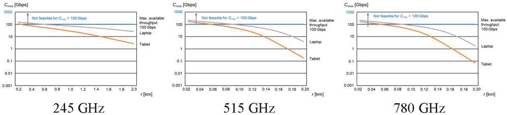
Figure 2 Downlink indoor transmission: Shannon channel capacity C [Gbps] versus range r, atmospheric attenuation for higher water vapor density (15 g/m) at 245 GHz and 80 % humidity at 515 and 780 GHz, for tablets and laptops, F 2 dB and W 10 GHz.
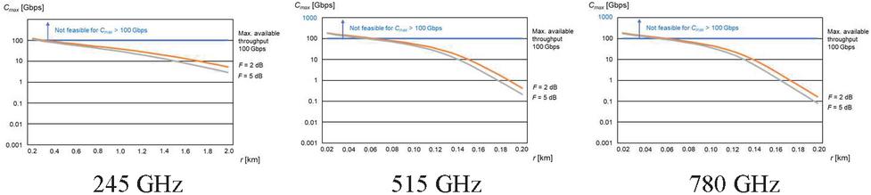
Figure 3 Uplink indoor transmission: Shannon channel capacity C [Gbps] versus range r, atmospheric attenuation for higher water vapor density (15 g/m) at 245 GHz and 80 % humidity at 515 and 780 GHz, for base stations, F 2 dB and 5 dB and W 10 GHz.
5.1 Indoor Scenario
In the 245 GHz frequency range reasonable radio range is feasible. However, the range is dropping fast with increasing frequency and bandwidth. More than 100 Gbps can be achieved up to around 200 m range. In the 515 and 780 GHz frequency range the achievable range for an aggregated throughput of 100 Gbps is limited to about 40 to 50 m. The throughput is dropping very fast with increasing range due to the high atmospheric attenuation. For practical applications the frequency range below 320 GHz is reasonable. Above 324 GHz (absorption/resonance peak) the atmospheric attenuation is increasing significantly, where only very short-range applications are envisaged. The achievable range in uplink and downlink are similar for the selected antenna configuration.
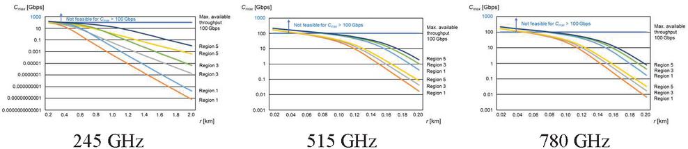
Figure 4 Downlink outdoor transmission: Shannon channel capacity C [Gbps] versus range r, atmospheric attenuation for higher water vapor density (15 g/m) at 245 GHz and 80 % humidity at 515 and 780 GHz, rain attenuation for regions 1, 3 and 5 (p 0.001 %), for tablets (lower curve per region) and laptops (upper curve per region), F 2 dB and W 10 GHz.
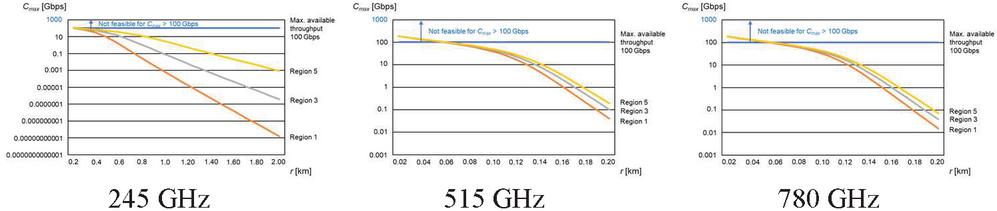
Figure 5 Uplink outdoor transmission: Shannon channel capacity C [Mbps] versus range r, atmospheric attenuation for higher water vapor density (15 g/m) at 245 GHz and 80 % humidity at 515 and 780 GHz, rain attenuation for regions 1, 3 and 5 (p 0.001 %), for base stations, F 2 dB and W 10 GHz.
5.2 Outdoor Scenario
In the 245 GHz frequency range reasonable radio range is feasible. However, depending on the device type in downlink and rain conditions the range is dropping fast with increasing frequency and bandwidth. More than 100 Gbps can be achieved for less than 200 m range. In the 515 and 780 GHz frequency range the achievable range for an aggregated throughput of 100 Gbps is limited to less than 40 to 50 m. The throughput is dropping very fast with increasing range due to the high atmospheric and rain attenuation. Beyond r 40 to 50 m the capacity is decreasing much faster than in the indoor scenario due to additional rain attenuation. For practical applications the frequency range below 320 GHz is reasonable. Above 324 GHz (absorption/resonance peak) the atmospheric attenuation in addition to rain attenuation is increasing significantly, where only very short-range applications are envisaged. Uplink and downlink range are similar for the selected antenna configuration.
6 Coherence Time of the Radio Channel
The time variance of the radio channel is described by the Doppler spread B or maximum Doppler frequency f and coherence time T [10, pp. 165]. During the time window T the radio channel impulse response stays nearly unchanged. The Doppler spread is a measure for the spectral broadening of a sinusoidal tone of carrier frequency f between the lower f – f and the upper limit f + f. f depends on the relative velocity v between receiver and transmitter, the angle of arrival of the received waves, the wavelength and the speed of light c. Depending of the type of the Doppler spectrum the coherence time is varying quite significantly, which follows from the spectral distribution of the received power versus angle of arrival. In [10, pp. 165], [28, pp. 30] and [29, pp. 119] simplified formulas are presented. A compromise description is expressed in [10, p. 166] for practical applications:
| (15) |
Figure 6 presents the coherence time versus mobile speed in the range up to 500 km/h and carrier frequency f (245/515/780 GHz).
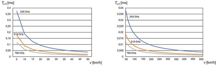
Figure 6 Expected coherence time T versus mobile speed v [km/h] and carrier frequency f as parameter.
The radio channel is only stationary for rather low carrier frequencies and mobile speed. In the case of very high carrier frequencies in the sub-Terahertz domain channel estimation has to be updated very fast and/or the mobile speed has to be reduced significantly. However, due to the low achievable range especially in outdoor scenarios sub-Terahertz systems will not be the preferred option for fast moving devices. Therefore, the sub-Terahertz frequency bands can reasonably only be applied for short range applications and low mobile speed (pedestrian speed). In the case of pedestrian speed systems up to 780 GHz may be applied with a coherence time in the order to 100 s. This will have an impact on the design of frame structures and the physical layer.
7 Means for Range Extension by Keeping Radiation Limits
The achievable radio range r in Equation (14) is limited by the maximum allowed EIRP according to Section 4. With higher base station antenna locations (Figure 7) h h – h an exclusion zone r for humans close to the base station can be avoided by ensuring the radiation limits. Figure 7 shows the geometry between transmitter and receiver. The following conditions need to be considered for downlink and uplink:
• Downlink: From the base station to the human the distance r’ is relevant to ensure that the radiation limits are ensured. The base station antenna height h is influencing r’ and r’, i.e., for higher base station antenna height the range r’ can be increased with increased transmit power P or EIRP by keeping the radiation limits for smaller distance r. In addition to the distance r’ also the antenna elevation diagram G() is influencing the radiation density at the human. For simplicity reasons the elevation directivity diagram of the Hertz-dipole is considered [7, p. 243].
• Uplink: From the mobile station to the base station the minimum distance r 0.1 m is assumed (c.f. Section 4). The base station antenna height has no influence on the radiation limits from the mobile station to the human.
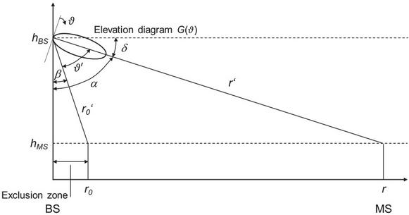
Figure 7 Propagation scenario between base station or access point and mobile station by considering the exclusion zone r for humans based on radiation limits.
Based on these conditions only the downlink is investigated, because the mobile station transmit power is limited due to the low distance r to the user. The atmospheric, rain and foliage attenuation components can be neglected for the short distance of a few meters between the human and the base station antenna compared to the free space path loss (Equation (5)). However, these attenuation components need to be taken into account for the propagation path between the base station and mobile station due to the bigger distance.
With Equation (13) and the geometry in Figure 7, the down tilt angle and the assumed elevation directivity antenna diagram the maximum allowed EIRP is derived as:
| (16) |
With increasing distance (exclusion zone) r the distance r’ between the base station and the human and also the effective antenna gain is increasing. Therefore, there is a minimum of EIRP. With respect to the rather short achievable range of sub-Terahertz-systems and low antenna height it is recommended not to apply down tilt antennas, i.e., . Figure 8 shows the evaluation of Equation (16). In the case of the antenna elevation diagram of a Hertz-dipole the minimum of EIRP is achieved for r/h 1:
| (17) |
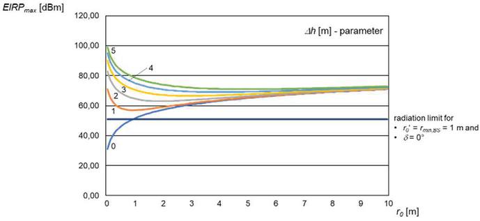
Figure 8 Maximum allowed EIRP versus exclusion zone r with the difference in antenna heigh h as parameter and down tilt angle .
This provides the design criterion for EIRP for a given difference in antenna height h, which allows to avoid any exclusion zone (r 0 m). The maximum allowed EIRP is increasing quadratically with h. With the increased EIRP compared to the reference in Section 4 for r 1 m and h 0 m
| (18) |
the radio range is increasing from r’ to r” towards cell edge. For additional atmospheric and rain attenuation components the relative range extension r”/ r’ follows from zero search of
| (19) |
r”/r’ is decreasing with range r’. If EIRP is increased by 20 dB compared to the radiation limit in Equation (13) for h 5 m, the radio range is increased to r”. For free space propagation this corresponds to a gain in range independent of r’ and with the parameters at f 245 GHz for atmospheric and rain attenuation (region 1) in Table 3 for r’ 0.1 km in r”/r’ 6.2 (indoor) and r”/r’ 2.7 (outdoor).
8 Remote Sensing Applications Based on Radar Concepts
Sensing applications are based on the concept of active Radars. Under the condition of radiation limits the achievable range and/or system throughput is rather limited even under idealized LOS propagation conditions. In the case that transmitter and receiver are at the same location, the monostatic Radar equation applies [8, pp. S1], which is extended by atmospheric and rain attenuation:
| (20) |
The scattering area or Radar cross section depends on the illuminated area. Under LOS conditions without atmospheric and rain attenuation the received power is decreasing with r, which is much faster than for communication systems. The reason is that the reflected waves at the scattering area correspond to spherical waves. When also additional atmospheric and rain attenuation are considered, there is a further significant impact on the achievable range r in the sub-Terahertz domain. With respect to the already very short range for communication systems in the sub-Terahertz domain the achievable range for remote sensing applications will be much shorter especially if radiation limits need to be considered.
9 Conclusions
Sub-Terahertz radio systems are considered as part of beyond 5G/6G systems. Currently, challenging technical requirements are discussed in terms of carrier frequency, very wide bandwidth and extremely high throughput. According to the ITU Radio Regulation there is an opportunity in the sub-Terahertz domain to identify significantly wider contiguous frequency bands in future WRCs in discussion with other service communities (radio astronomy, earth exploration satellites).
In the case that humans are involved in use cases and applications regulated radiation limits of electromagnetic power need to be respected, which is limiting the achievable range. Due to the short range and high base station transmit antenna gain sub-Terahertz systems are mainly operated under near field or Fresnel region conditions. Mobile devices with lower antenna gain may be operated under far-field conditions.
The overall effective path loss is significantly affected by free space propagation (first Fresnel zone is usually free of obstacles), atmospheric attenuation, rain attenuation and foliage loss, which should be avoided in practical deployment scenarios. Wall penetration loss scenarios are not considered, because communication is not possible without repeaters. The system performance in terms of capacity versus range is much better for indoor scenarios due to additional rain attenuation in outdoor scenarios. Atmospheric attenuation can only be avoided in the vacuum, e.g., for inter-satellite links or air-conditioned rooms. For carrier frequencies below around 300 GHz rather high data throughput for a radio range of up to about 200 m is feasible even under radiation limits. This range is decreasing, if further safety factors are applied to radiation limits. Above 324 GHz the atmospheric attenuation is growing fast. Higher base station antenna locations can increase range reasonably in downlink. In the uplink the range or data throughput are limited by the radiation limits and short distance to humans.
The significant range limitations need to be considered for the definition of use cases and applications especially for high throughput systems and where radiation limits must be respected to avoid health effects at humans. For backhaul and fronthaul systems or microwave links less stringent requirement on radiation limits apply, if no humans are involved in the radio path such as cable replacements in data centers, backhaul links and for inter-satellite links in the vacuum due to good propagation conditions.
References
[1] EMPOWER project: HORIZON 2020 ICT, Deliverable 2.2: First Technology roadmap for advanced wireless. https://ec.europa.eu/research/participants/documents/downloadPublic?documentIds=080166e5c8cbd3de\&appId=PPGMS.
[2] Networld2020 European Technology Platform: Strategic Research and Innovation Agenda (SRIA) 2021 – 2027, September 2020, based on EU EMPOWER project. https://bscw.5g-ppp.eu/pub/bscw.cgi/d367342/Networld2020\%20SRIA\%202020\%20Final\%20Version\%202.2\%20.pdf.
[3] ITU-R: IMT Vision – Framework and overall objectives of the future development of IMT for 2020 and beyond. Recommendation ITU-R M.2083-0 (09/2015), https://www.itu.int/dms\_pubrec/itu-r/rec/m/R-REC-M.2083-0-201509-I!!PDF-E.pdf.
[4] ITU: Radio Regulations Edition 2020, Vol. I to Vol. IV. https://www.itu.int/dms\_pub/itu-r/opb/reg/R-REG-RR-2020-ZPF-E.zip.
[5] Rappaport, T.S., Xing, Y., Kanhere, O., Ju, S., Madanayake, A., Mandal, S., Alkhateeb, A., and G.C. Trichopoulos: Wireless Communications and Applications Above 100 GHz: Opportunities and Challenges for 6G and Beyond. IEEE Access, Vol. 7, 2019, pp. 7829, https://ieeexplore.ieee.org/stamp/stamp.jsp?tp=\&arnumber=8732419.
[6] FCC: Notice of Proposed Rulemaking. Document FCC 18-21, February 2018.
[7] Zinke, O. and H. Brunswig: Lehrbuch der Hochfrequenztechnik. Vol. I, p. 258, Springer-Verlag, Berlin, Heidelberg, New York, 2nd Edition, 1973.
[8] Meinke/Gundlach: Taschenbach der Hochfrequenztechnik. Berlin: Springer-Verlag 1986.
[9] Geng, N. and W. Wiesbeck: Planungsmethoden für die Mobilkommunikation. Springer Verlag, Berlin, 1998.
[10] Rappaport T.S.: Wireless Communications – Principles & Practice. New Jersey: Prentice Hall 1996.
[11] Federal Communications Commission: Millimeter Wave Propagation: Spectrum Management Implications. Office of Engineering and Technology, New Technology Development Division, Bulletin Number 70, July 1997.
[12] Kukshya, V.: Wideband Terrestrial Path Loss Measurement Results for Characterization of Pico-cell Radio Links at 38 GHz and 60 GHz Bands of Frequencies. Thesis submitted to the Faculty of Virginia Polytechnic Institute and State University, Blacksburg, Virginia, June 19, 2001.
[13] Meng, Y. S. and Y. H. Lee: Investigations of Foliage Effect of Modern Wireless Communication Systems: A Review. Progress in Electromagnetics Research. Vol. 105, 313–332, 2010.
[14] Rappaport, T. S., Y. Qiao, J. I. Tamir, J. N. Murdock and E. Ben-Dor: Cellular Broadband Millimeter Wave Propagation and Angle of Arrival for Adaptive Beam Steering Systems. IEEE Radio and Wireless Symposium (RWS), Santa Clara, CA, January 15-18, 2012, pp. 151.
[15] Geng, S., J. Kivinen, X. Zhao, and P. Vainikainen: Millimeter-Wave Propagation Channel Characterization for Short-Range Wireless Communications. IEEE Transactions on Vehicular Technology, Vol. 58, No. 1, January 2009, pp. 3.
[16] ITU-R: Propagation data and prediction methods for the planning of indoor radiocommunication systems and radio local area networks in the frequency range 900 MHz to 100 GHz. Recommendation ITU-R P.1238-7, P Series Radiowave propagation, (02/2012).
[17] Brodhage, H. and W. Hormuth: Planung und Berechnung von Richtfunkverbindungen. 10th updated edition, Siemens AG, Berlin – Munich, 1977.
[18] Slocum, D.M., Slingerland E.J., Giles, R.H., Goyette, T.M.: Atmospheric absorption of terahertz radiation and water vapor continuum effects. Journal of Quantitative Spectroscopy & Radiative Transfer, 2013, http://dx.doi.org/10.1016/j.jqsrt.2013.04.022.
[19] Sayed Amir Hoseini, A.A.: A Theoretical Study of the Effect of Molecular Absorption and Re-radiation on Millimeter Wave and Terahertz Wireless Networking. PhD Thesis, University of New South Wales, Australia, November 2017.
[20] ITU-CCIR: CCIR Rep. 721-1, Recommendations and Reports of the CCIR, 1982, XV Plenary Assembly, Geneva 1982, Vol. 5.
[21] Jung, V. and H.-J. Warnecke: Handbuch für die Telekommunikation. Springer Verlag, Berlin, second edition, 2002.
[22] Rappaport, T.S., Sun, S., Mayzus, R, Zhao, H., Azar, Y., Wang, K., Wong, G. N., Schulz, J. K., Samimi, M. and F. Gutierrez, Jr.: Millimeter wave mobile communications for 5G cellular: It will work! IEEE Access, Vol. 1, pp. 335–349, May 2013.
[23] Rappaport, T.S., Murdock, J.N. and F. Gutierrez, Jr.: State of the art in 60-GHz integrated circuits and systems for wireless communications. Proceedings of the IEEE, Vol. 99, no. 8, pp. 1390–1436, Aug. 2011.
[24] Qingling, Z. and J. Li: Rain attenuation in millimeter wave ranges. Proceedings 7th International Symposium of Antennas, Propagation and EM Theory (ISAPE), October 2006, pp. 1–4.
[25] Federal Communications Commission: Millimeter Wave Propagation: Spectrum Management Implications. Office of Engineering and Technology, New Technology Development Division, Bulletin Number 70, July 1997.
[26] ICNIRP: ICNIRP Guidelines for limiting exposure to electromagnetic fields (100 kHz to 300 GHz). ICNIRP publication 2020.
[27] Thomas, J.B.: An Introduction to Statistical Communication Theory. John Wiley & Sons, New York, 1969, pp. 568.
[28] Tse, D. and P. Viswanath: Fundamentals of Wireless Communication. Cambridge University Press, Cambridge, 2005.
[29] Steele, R.: Mobile radio communications. Pentech Press Publishers, London and IEEE Press, New York, 1994.
Biography
Werner Mohr was graduated from the University of Hannover, Germany, with the Master Degree in electrical engineering in 1981 and with the Ph.D. degree in 1987.
Dr. Werner Mohr joined Siemens AG, Mobile Network Division in Munich, Germany in 1991. He was involved in several EU funded projects and ETSI standardization groups on UMTS and systems beyond 3G. Werner Mohr coordinated several EU and Eureka Celtic funded projects on 3G (FRAMES project), LTE and IMT-Advanced radio interface (WINNER I, II and WINNER+ projects), which developed the basic concepts for future radio standards. Since April 2007 he was with Nokia Solutions and Networks (now Nokia) in Munich Germany, where he was Head of Research Alliances. In addition, he was chairperson of the NetWorld2020 European Technology Platform until December 2016. Werner Mohr was Chair of the Board of the 5G Infrastructure Association in 5G PPP of the EU Commission from its launch until December 2016. He was chair of the “Wireless World Research Forum – WWRF” from its launch in August 2001 up to December 2003. Werner Mohr was member of the board of ITG in VDE from 2006 to 2014. He is co-author of a book on “Third Generation Mobile Communication Systems”, a book on ”Radio Technologies and Concepts for IMT-Advanced” and a book “Mobile and Wireless Communications for IMT-Advanced and Beyond”. In December 2016 Werner Mohr received the IEEE Communications Society Award for Public Service in the Field of Telecommunications and in November 2018 he received the VDE ITG Fellowship 2018. In May 2019 Werner Mohr received the WWRF Fellowship.
In March 2021 he retired from Nokia and is now active as consultant and lecturer at TU Berlin, Germany.
Journal of Mobile Multimedia, Vol. 19_1, 215–238.
doi: 10.13052/jmm1550-4646.19111
© 2022 River Publishers