Massively Flexible Mobile Systems
André Perdigão1, 2,*, José Quevedo1, Daniel Corujo1, 2 and Rui L. Aguiar1, 2
1Instituto de Telecomunicações, Aveiro, Portugal
2University of Aveiro, Aveiro, Portugal
E-mail: andreperdigao@ua.pt
*Corresponding Author
Received 19 March 2024; Accepted 02 December 2024
Abstract
5G network is expected to provide mMTC (massive Machine Type Communications or massive Internet of Things [mIoT]) slices in the near future, coinciding with expectations for a significant increase in the IoT global market. Many new IoT use cases are anticipated to be deployed using 5G which requires mMTC performance. Release 17 introduces several mMTC features. However, as of release 19, 3GPP does not claim full support of mMTC slices.
Even if 5G cannot fully support mMTC network slices yet, several network features are already standardized and included in commercial-graded 5G networks. These features allow for the reconfiguration of the network to provide communication performance close to what is provided in mMTC slices. This paper analyzes and evaluates several of these features, demonstrating that current 5G networks are already capable of supporting some of the mMTC use cases expected to be deployed in the future.
Keywords: 5G, mMTC, testbed, network slicing, IoT.
1 Introduction
The global IoT (Internet of Things) market has experienced significant growth in recent years, sustaining approximately a 20% increase. Forecasts indicate an expected growth of 19% until 2027 according to IoT Analytics.1 Alongside this market expansion, there has been a notable increase in the number of connected IoT devices, rising around 18-23% annually and predicted to continue growing by 16% until 2027.2 It’s estimated by GSMA3 that the connected IoT devices will reach 39 billion by 2030.
This substantial growth is correlated with the increase in IoT use cases designed, researched, developed, and deployed in recent years. GSMA’s report in [1] presents several impactful use cases across Agriculture, Climate, Health, Humanitarian Assistance, Transport, and Utilities. Additionally, GSMA highlights some technologies that will impact the IoT ecosystem. Since 5G is the most recent and developed technology, it is expected that it will significantly influence the IoT ecosystem in the near future.
5G incorporates a mMTC (massive Machine Type Communication) type of slice, designed to accommodate many end devices transmitting small amounts of data with minimal power consumption. mMTC is fundamental for supporting numerous IoT use cases within the 5G network. The development and standardisation of 5G involves periodic freezing of releases, occurring every one to two years. For instance, Release 15 (R15) concluded its updates in 2019 with support for the eMBB (enhance Mobile Broadband) slice. Following this, Release 16 (R16) finalized updates in 2020 with additional support for URLLC (Ultra Reliable Low Latency Communication) slices. Release 17 (R17) was frozen in 2022 with support to some mMTC features,4 and Release 18 (R18) is projected to be complete in 2024. However, 3GPP until Release 19 has not claimed the complete support of mMTC slices.
Despite the lack of full support for mMTC in the current frozen releases, numerous 5G features and functionalities already facilitate the configuration of the network to support a slice similar to mMTC. Some of the features include BWP (Bandwidth Part) and DRX (Discontinuous Reception) supported since R15, Maximum MIMO (Multi-Input Multi-Output) layers adaptation and Reduced RRM (Radio Resource Management) measurement in idle/inactive state since R16, along with SDT (Small Data Transmission) and RedCap (Reduce Capabilities) introduced in R17, and further RedCap enhancements in R18. Considering these capabilities, this paper introduces several of the available features relevant in the mMTC context in a 5G network, validating some of them using a real-world SA commercial 5G network.
The remaining sections of the document are structured as follows: sec:2-rw offers a brief analysis of the related work; sec:3-mMTCfeatures introduces various 5G features that offer communication capabilities and performance similar to a mMTC slice; sec:4-validation provides a brief overview of the 5G network and details the methodology used to validate the performance impact of several presented features; sec:5-results presents the outcomes obtained from the validation of each 5G feature; sec:6-discussion offers a comprehensive discussion of the results and concludes the document.
2 Related Work
As detailed in [1], various wireless technologies are available to support IoT use cases. Extensive research has been conducted on these technologies. For instance, [2] analyzes the trade-offs among different wireless technologies in Industrial IoT applications. Meanwhile, [3] compares Wi-Fi, Bluetooth, Zigbee, 6LoWPAN, and other proprietary solutions, offering an overview and guidelines on each technology’s functionality and trade-offs. Additionally, [4] evaluates the use of different cellular technologies in IoT, providing insight into their performance. Authors in [5] assess emerging wireless technologies anticipated to impact IoT post-2020.
The range of technologies supporting IoT varies widely. For instance, LTE-M and LoraWAN offer low throughput but cover medium to high distances. Wi-Fi and Bluetooth, on the other hand, are short-range technologies with varying throughput. Satellite technologies provide almost global coverage but with limitations in throughput and device density per square kilometre. Cellular technologies like 2G and 4G offer medium to high coverage with high throughput. However, each technology, as extensively analyzed in the literature, comes with its own limitations, being unable to address all use cases.
5G is renowned for its inherent flexibility with network slicing and its anticipated extensive global coverage. With this, 5G is expected to cater to most use cases, offering support from low to high throughput. It can adapt communication performance reducing end-device power consumption, potentially enabling end devices to operate for over a decade on a single battery charge. Therefore, 5G can serve as a single technology replacement in scenarios with multiple IoT technologies and distinct performance requirements.
Current research exhibits ongoing efforts to explore 5G’s application in deploying IoT use cases. Authors in [6, 7] analyze key enablers and challenges faced by 5G to support IoT use cases. Moreover, [7] provides a performance comparison between eMBB slice, URLLC slice, LTE-M, NB-IoT and an envisioned NR-LiTE.
Despite eMBB slices being supported since R15 and URLLC slices since R16 of the 5G network, there is a knowledge gap of when the 5G network will fully support mMTC slices. Numerous IoT use cases require a high device density, having each device periodically send low amounts of data while being powered by limited power sources like batteries. To support such use cases 5G needs mMTC slices.
Considering this, this paper analyzes 5G features that serve as the foundation for supporting mMTC slices in a 5G network, while providing some scenarios where they can be used. To support the analysis, an evaluation of several features is performed using a real-world commercial graded 5G network. This evaluation demonstrates the performance impact and validates previous claims, showing that 5G networks can already provide performance that resembles the expected performance of mMTC slices.
3 5G mMTC Features
This section introduces several standardized 5G features capable of adjusting network slice performance to resemble an mMTC slice. In an mMTC scenario, the 5G network is expected to support a high device density, providing connectivity to more than a million devices per square kilometre, all while ensuring low power transmission, as most devices are battery-powered. Therefore, the features analyzed focus on enabling higher connection density or reducing end devices’ power consumption. The section begins with a brief description of the 5G features and their effects. Additionally, the section offers an overview of the features available for testing in the used 5G network, along with the existing limitations in terms of 5G modules at the moment.
3.1 mMTC Features
tab: Standardized features presents several of the standardised 5G network features standardized in [8, 9, 10, 11] that approximate communication performance to simulate an mMTC slice. The feature order takes into account their similarity and performance impact. The table includes feature numbering, the feature name, the initial release when it was standardised, a brief description, and a summary of its impact. It’s important to note that even though a feature may have been introduced in early releases, it doesn’t necessarily mean it was fully supported or provides enough configuration granularity in the 5G network to be used in a specific network slice. Some features might affect entire networks or cells in the earlier releases, resulting in configurations that lack the granularity needed to exclusively impact a network slice.
| N. | Feature | Rel. | Description | Impact Summary |
| 1 | RedCap (Reduce Capabilities) | 17 | Usage of end devices with lower capabilities to reduce hardware requirements and energy consumption. | Limited hardware support, reduced energy consumption. |
| 2 | RRM (Radio Resource Management) measurement relaxation | 16 | Reduces requirements for monitoring neighbour cells, saving energy and resources. | Lower energy consumption, reduce signalling overhead. |
| 3 | Idle State | 15 | Allows UE to stay in a lower energy state while retaining control plane session, but releasing user plane session. | Reduce energy consumption, and higher latency for first packet exchanges. |
| 4 | Inactive State | 15 | Intermediate state between idle and connected state; reducing uplink capabilities but maintaining user plane session. | Higher latency of first packets, reduced energy consumption. |
| 5 | Inactivity Timer | 15 | Sets the time for UE to wait since the last user plane exchange before transitioning to the idle or inactive state. | Time and energy spent in the connected state when UE not communicating. |
| 6 | Fast transition out of CONNECTED state | 16 | Allows UEs to quickly transition from connected state to idle or inactive state without waiting for the inactive timer. | Reduce power consumption during state transition. |
| 7 | SDT (Small Data Transmission) | 17 | Enables UEs to transmit or receive small amounts of user plane data in the inactive state. | Reduced energy usage for low-data transmissions. |
| 8 | DRX (Discontinuous Reception) | 15 | Cycles of active and inactive periods for device to monitor PDCCH. | Decreases energy spent on monitoring, increased downlink latency. |
| 9 | Extended DRX in idle/inactive state | 16 | Extends DRX cycle time for idle and inactive states; reducing control plane channel monitoring in these states. | Reduces energy consumption when in an idle or inactive state. |
| 10 | WUS (Wake-Up Signal) | 16 | Signals UE to monitor PDCCH (Physical Downlink Control Channel) only for the WUS signal in each DRX cycle; reducing PDCCH monitoring time. | Decreased energy usage for PDCCH monitoring. |
| 11 | PDCCH monitoring adaptation | 17 | Network informs UEs whether to skip PDCCH monitoring; UEs monitor PDCCH after sending an SR request without response. | Reduced energy spent on PDCCH monitoring. |
| 12 | SR (Scheduling Resource) transmission | 15 | UE request uplink slot via uplink control channels, and the network grants uplink slot for UE to transmit uplink packets. | Efficient uplink resource allocation, higher energy consumption and latency due to control communication. |
| 13 | Configured Grant | 16 | Network reserves slots for device/group uplink transmission, reducing control channel overhead during uplink communication. | Reduced latency, lower energy consumption during uplink. |
| 14 | BWP (Bandwidth Part) | 15 | Divides cell spectrum into bandwidth subsets for UE communication. | Enhanced spectrum utilization, adaptive communication. |
| 15 | BA (Bandwidth Adaptation) | 15 | Permits UEs to transition between active BWPs in the cell depending on communication requirements. | Energy-efficient communication, adaptive bandwidth usage. |
| 16 | Maximum MIMO Layers Adaptation | 16 | Restricts the number of MIMO layers in each BWP, limiting bandwidth and reducing UE energy consumption. | Improved power savings with adaptable MIMO configurations. |
| 17 | MICO (Mobile Initiated Connection Only) | 15 | Only UE can request transition from the idle state to the connected state. | Reduce energy consumption monitoring, limited downlink communication. |
| 18 | Asynchronous Type Communication | 15 | AMF stores session updates until UE re-enters the connected state, and transmits updates upon UE reconnection. | Postpone updates, lower signalling overhead, efficient session context handling. |
| 19 | High Latency Communication | 16 | Stores downlink packets for unreachable UE due to power saving features, forwards stored packets upon UE transition to connected state. | Improved packet delivery, reduced data loss during power-saving states. |
Each of the presented features has a different impact on performance depending on the scenario. Feature-1 limits hardware and software, making these devices unsuitable for use cases demanding higher throughput or when certain features are not supported by RedCap. Feature-2 only impacts static UEs or low-mobility UEs positioned out of the edge of cell coverage. Feature-3 requires UEs to remain inactive for extended periods - ranging from several minutes to hours or even days. Feature-4 also necessitates inactive periods, but for a shorter duration, and when coupled with Feature-7, it’s viable for UEs to transmit small amounts of data without state transition. A good configuration of Features-5 and 6 can optimize the utilization of Features-3 and 4.
Features-8, 9, and 10 trade downlink latency for reduced energy consumption. They are best suited for scenarios where the requirement of downlink latency rounds the order of multiple dozens of milliseconds or higher. Feature-11 is preferable for use cases that demand lower downlink latencies. Feature-12 is more suitable for non-periodic uplink transmissions with high reliability, while Feature-13, in user-specific allocation, is best for periodic transmissions, as UEs need to transmit in all allocated slots, potentially wasting energy and network resources in unused slots. Feature-13 with group allocations may serve for irregular transmissions but carry the risk of collisions, leading to packet loss and reduced reliability.
Features-14, 15, and 16, when used collectively, enhance spectrum resource utilization and make transmission more energy-efficient. Features-17, 18, and 19 are applicable only when there are no downlink latency requirements since packets are delivered to UEs only when they transition to the connected state, reliant on the uplink transmission frequency or the UE’s decision to reconnect to the network.
3.2 Current Landscape
Even if the features presented in the subsection above were already standardized and are present in the 3GPP documentation, not all can be used at the moment, or are not available in all 5G networks, since every 5G network provider takes its own deployment decisions, and may not support all the standardized features. So this subsection discusses the features above supported by the 5GAIner network [12] (a commercial graded SA 5G network available for validating and demonstrating the impact of the above features in vertical-based scenarios) considering its current limitations. Then it discusses the limitations of the currently available 5G modules, which also impact the availability of some of the above features.
3.2.1 5GAIner available features
5GAIner is a commercial-graded SA 5G network, supporting some R17 features, further presented in sec:4.1-5GAIner. Throughout the 5GAIner documentation, the current release deployed in the network supports the following features: RedCap, idle state, inactive state, inactivity timer, fast transition out of CONNECTED state, DRX, SR transmission, configured grant, BWP, BA, Maximum MIMO Layers adaptation, MICO, Asynchronous Type Communication, and High Latency Communication.
Even though the 5GAIner network should ideally support all these features, certain limitations prevent the evaluation of some. Specifically, the features that cannot be evaluated include BWP, BA, Maximum MIMO Layers Adaptation, Asynchronous Type Communication, MICO, and High Latency Communication.
The inability to evaluate BWP, BA, and Maximum MIMO Layers is attributed to spectrum access limitations, as the 5GAIner network uses a 20 MHz spectrum given by a Portuguese operator, to use in this experimental network for research and development of 5G technologies.
As for the other parameters, they are configured on the core, which is compliant with most R17 standards, while the RAN has minimal support for R17 functionalities. Therefore, even after configuring the features on the core, there was no impact on communications. This could be due to a lack of support by the RAN, or since the module used is an engineering sample, it may lack some functionalities necessary to support these features.
3.2.2 Module limitations
R17 5G modules are under development and are projected to reach the commercial stage by the second Quarter of 2024. So at the moment only development stage RedCap R17 5G modules are available. Due to this situation, there is no assurance that the current accessible end devices support all the features presented in this document. Therefore, this validation only provides an early evaluation of the potential performance of some of these features.
4 Validation
To assess the performance impact of the aforementioned features, the 5GAIner network was utilized, which is detailed in the subsequent subsection. This is followed by a subsection explanation of the setups and methodologies employed to evaluate the performance of each 5G feature.
4.1 5GAIner
A comprehensive description of the 5GAIner network is available in [12]. Despite the document illustrating the 5GAIner network while in its R15 form, the description and assessment remain accurate, given the absence of significant changes in the hardware and its baseline performance. 5GAIner is a 5G SA commercial-grade network, which already implements some R17 functionalities, operating within a commercial-graded real-world infrastructure placed over various locations, including the Instituto de Telecomunicações (IT) of Aveiro and the University of Aveiro. This infrastructure primarily serves research purposes, providing a platform for the development, testing, and validation of diverse 5G technologies and use cases.
The 5GAIner infrastructure operates within a reserved band owned by Altice, a major telecommunications operator in Portugal. The current antenna configurations used in the evaluation are detailed in tab:5gainer, offering crucial insights into the obtained network performance.
Table 2 gNodeB technical specifications
| Specification | Values |
| Maximum bandwidth | 20 MHz with 30kHz subcarrier spacing |
| Frequency band | Center frequency of 3790.02 MHz (n78 band) |
| Output power per port | 24 dBm |
| Demultiplexing | TDD |
| DL Modulation | BPSK; QPSK; 16/64/256QAM |
| UL Modulation | BPSK; QPSK; 16/64QAM |
| MIMO | 4T4R |
| Slot assignment | 4 Downlink: 1 Uplink (Slot structure 2) |
4.2 Evaluation Setup and Performance Measurements
To evaluate the performance impact of each 5G feature, it was used the setup depicted in fig: setup. This setup includes a UE, a 5G network, and a server directly connected to the 5G network. The UE consists of a computer serving as an end device. This board connects via Ethernet to a server directly connected to the 5G network. This connection’s sole purpose is to measure network latency. Additionally, the 5G module, which provides 5G connectivity, is connected to a computer (HP Elitebook 645 G6) via a USB digital tester (FNIRSI FNB58) capable of measuring: Voltage, Current, Power, Capacity, and Energy consumed.
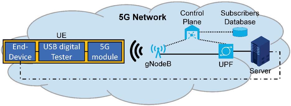
Figure 1 Evaluation setup.
Energy Consumption measurement: is made using the USB digital tester, which provides energy in watts spent by the 5G end device.
Latency measurement: In the uplink scenarios, the server transmits a packet to UE1 via the Ethernet connection, which the UE1 then forwards through the 5G network to the server. Conversely, the downlink measurement is performed in the opposite direction. Latency in milliseconds is calculated by measuring the time difference between the moment packets are sent from the server and their arrival.
Throughput measurement: is obtained using metrics from the 5G RAN, where it is possible to obtain the throughput of each UE every second in Mbps on the RLC layer.
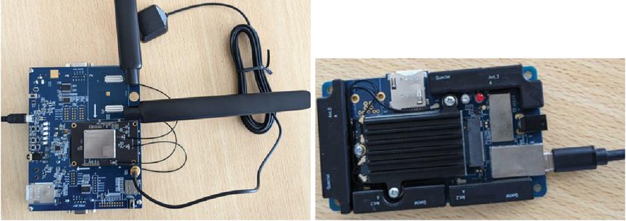
Figure 2 RedCap R17 Engineering sample (left) and R15 (right) 5G modules.
End devices: For most of the measurements, an R17 RedCap 5G module (Quectel 5G RedCap RG255C-GL) in the development stage was used. This module is shown in the left image of fig: 5G modules. Since the module is in the development stage, the current hardware differs from the commercial version, and the module also employs an experimentation board originally designed for a 4G module. This disparity may affect the module’s performance, possibly affecting energy consumption, latency and throughput compared to the future commercial version. Nevertheless, it can demonstrate the expected performance of a RedCap device.
To understand redcap capabilities, it is compared with a commercial version of an R15 5G module (Quectel 5G RM500Q-GL), shown in the right image of fig: 5G modules. As this module is a commercial version, it already demonstrates the complete performance expected from an R15 5G device.
5 Results
This section presents the performance results obtained with each of the different functionalities. This section is divided into subsections analyzing a specific feature or comparing equivalent features with similar functionality, explaining the test performed, presenting the results, and analyzing them.
To obtain the results presented in this section, each evaluation was conducted multiple times verifying its consistency. Then, one of the tests performed was selected to present the results.
5.1 RedCap vs R15
As explained earlier, the RedCap used is not a commercial version, so its performance may differ from the final modules. Since RedCap represents the limitation of the 5G hardware/software of the end device used for communication, this evaluation compares the performance of an R15 5G module against the RedCap device. This comparison provides a reference point and a better understanding of the performance expected from RedCap devices.
To compare the performance of both devices, the default configurations of the 5GAIner network were used, which include an idle state with a 10-second inactivity timer, no DRX, and a configured grant for 250 ms after transmission. Additionally, SR transmission with a period of 20 ms is used if no transmission occurs for more than 250 ms. The comparison involves verifying the maximum throughput, latency, and energy consumption with and without transmission for both devices.
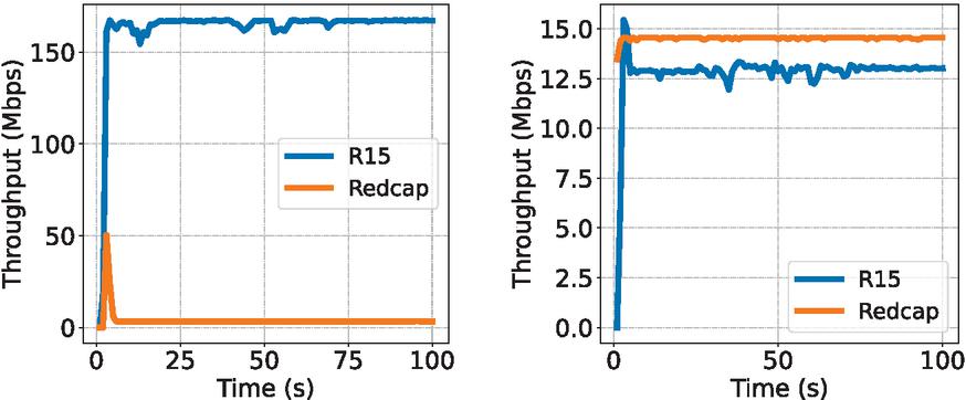
Figure 3 RedCap and R15 modules maximum downlink (left) and uplink (right) throughput.
The maximum throughput obtained for both devices is shown in fig: Throughput. As expected, the RedCap device exhibits more limited throughput due to constraints in antenna number and modulation schemes. Despite the limitations of the RedCap device, downlink results are much lower than expected. The downlink throughput of the redcap device must be much higher than the consistent 3 Mbps obtained throughout most of the test, possibly the 50 Mbps peak seen at the beginning of the test, considering that the module description,5 presents a maximum DL throughput of 150 Mbps. This limitation could be attributed to the limitations of the engineering sample or the experimentation board used.
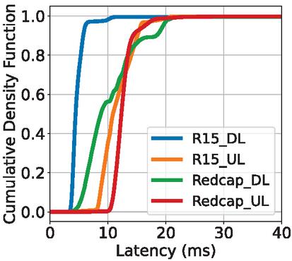
Figure 4 RedCap and R15 modules latency results.
Latency was measured using the setup presented above, with the UE sending 1000 bytes every 10 ms. The results are shown in fig: Latency. Currently, the obtained results indicate that the RedCap has higher latency. While this difference could potentially be reduced in the commercial module, the latency values may remain higher than with non-RedCap devices.
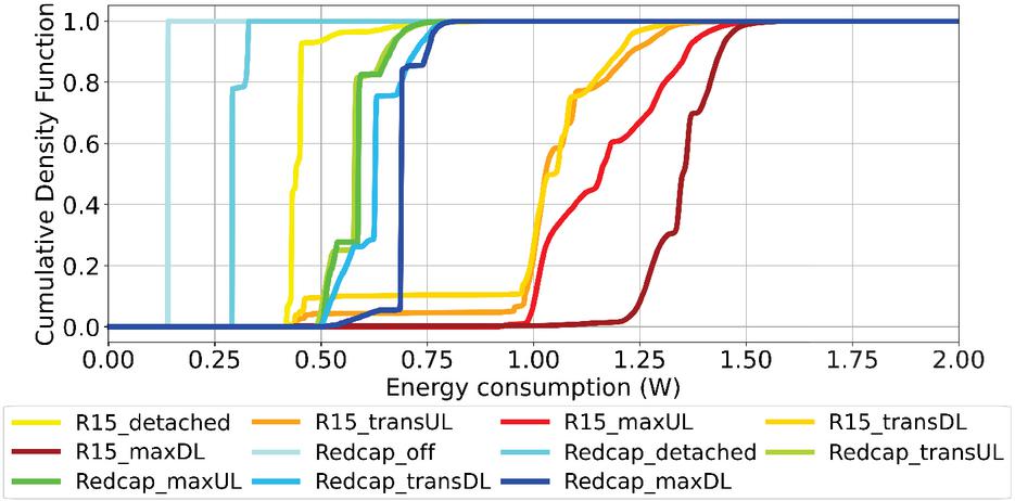
Figure 5 RedCap (left) and R15 (right) modules energy consumption results.
The energy consumption of the modules is shown in fig: Energy Consumption. It is demonstrated that the experimentation board alone consumes at least 0.1W (RedCap_off), a significant portion of the energy consumed by the RedCap device, resulting in significantly poorer results. Despite the increase in energy consumption caused by the evaluation board, the results show that the RedCap device consumes much less energy than a non-RedCap end device. With a commercial version featuring a specialized experimentation board, this energy consumption should be further reduced, thereby minimizing the energy consumption of the RedCap device.
The remaining tests will exclusively utilize the RedCap device since the objective is to measure the impact of the features and not to compare the impact between devices. It’s important to note that the energy consumption results were obtained with the RedCap module, and the higher consumption caused by the experimentation board is consistently observed across all measurements. Therefore, a commercial module will be optimized, resulting in lower values. This optimization will magnify the impact of the observed differences.
5.2 Idle vs Inactive State
To compare the Idle state and Inactive state, the energy consumption of each state was measured, along with the latency of the first packet. This latency measurement evaluates the impact of the transition to the connected state in the transmission.
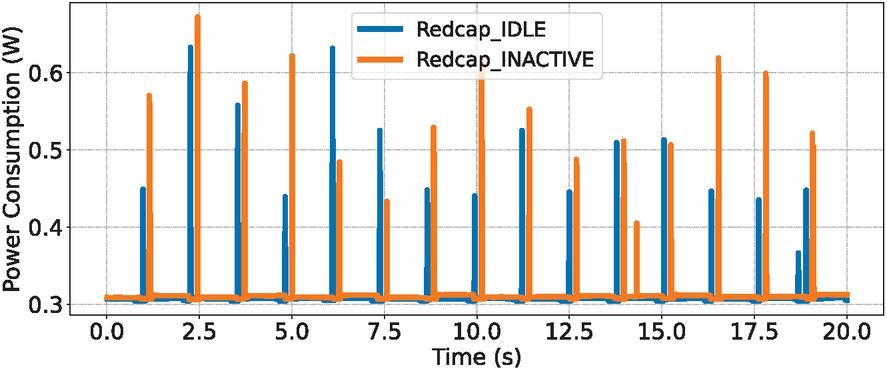
Figure 6 Idle state and Inactive state energy consumption.
The energy consumption results are shown in fig: Idle Inactive Energy, demonstrating the energy consumption while the end device is in each state. The results reveal that the Inactive state exhibits slightly higher energy consumption, with a mean energy consumption of 0.308 W for the idle state and 0.313 W for the inactive state. This is anticipated, as the inactive state maintains the user plane session.
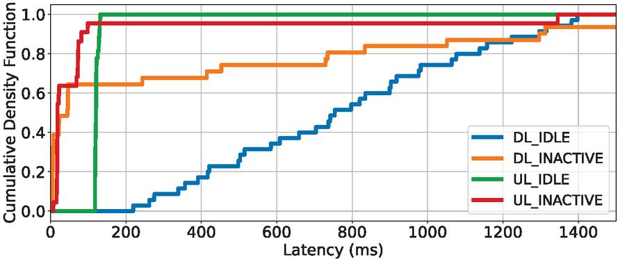
Figure 7 Idle state and inactive state latency results.
The latency results are presented in fig: Idle Inactive Latency. As expected, the inactive state has significantly lower latency compared to the idle state, as it does not require reestablishing the user plane session. This demonstrates that depending on the use case requirements for latency and energy consumption, one state may be better suited than the other.
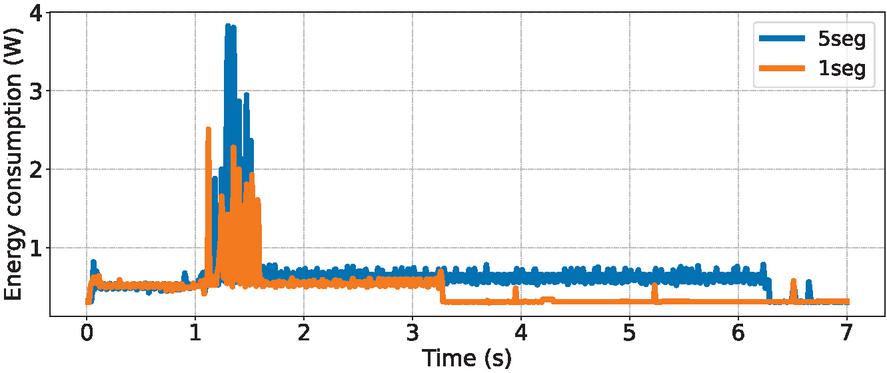
Figure 8 Inactivity timer energy results.
5.3 Inactivity Timer
To assess the impact of the inactivity timer, the duration a UE remains in the connected state was examined when the inactivity timer was set to 1 and 5 seconds. This involved measuring the UE’s energy consumption as it transitioned from the idle state to the connected state and back to the idle state. fig: Inactivity Timer Energy presents the results, indicating that the inactivity timer directly affects the duration the UE remains connected since the last transmission, as evidenced by the energy consumption exceeding 1 W.
5.4 SR Transmission vs Configured Grant
SR transmission and configured grant are two different scheduling mechanisms utilized in a 5G network.6 To compare their performance, packet transmissions of 100 bytes were conducted at various intervals ranging from 10 ms to 12 seconds. SR transmission uses a 40-slot SR period. providing 20 ms between slots for scheduling requests. On the other hand, the configured grant allocates resources for 250 ms after the last UL or DL transmission, after which it defaults to the SR transmission configuration with a 40-slot SR period. Throughout all tests, the inactivity timer is set to 10 seconds.
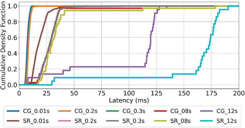
Figure 9 Performance of SR transmission (SR) and Configured Grant (CG) in Latency for different packet intervals.
The latency results are shown in fig: SR_CG Latency. The configured grant exhibits better performance for packet intervals below 250 ms. Between packet intervals of 250 ms and 10 seconds, both mechanisms have similar latency performance. Specifically, SR transmission maintains a latency of around 20 to 40 ms for packet intervals below 10 seconds. However, for packet intervals exceeding the inactivity timer, performance deteriorates significantly due to the state transition effects.
The Energy consumption results are shown in fig: SR_CG Energy Consumption, demonstrating that SR transmission exhibits lower energy consumption for any packet interval compared to the configured grant.
5.5 DRX
To assess the impact of DRX, a comparison was conducted between performance with and without DRX, utilising a 320 ms long cycle and 10 ms on duration, which is a default value pre-configured on the 5GAIner network. Additionally, the impact of DRX was examined with and without transmission (sending a packet every half second). Subsequently, the effect on downlink latency was evaluated across various long-cycle values for DRX.
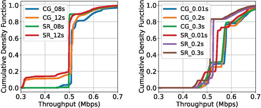
Figure 10 Performance of SR transmission (SR) and Configured Grant (CG) in Energy Consumption for different packet intervals.
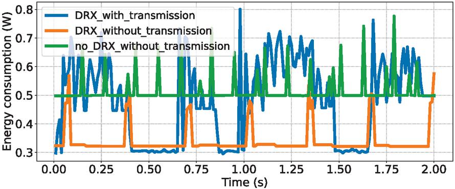
Figure 11 DRX Cycle Energy Consumption with and without transmission.
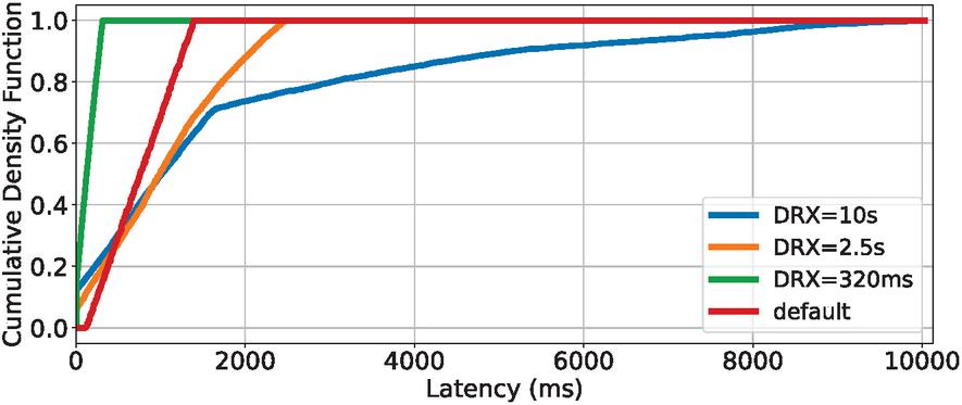
Figure 12 DL Latency impact with different cycles of DRX.
fig: DRX Energy Consumption illustrates the energy consumption when DRX is enabled. As expected, it significantly impacts energy consumption, particularly during periods without transmission.
fig: DRX Latency shows the impact on the downlink latency when transmitting a downlink packet every 5 seconds. It demonstrates that a higher DRX cycle results in higher downlink latency, with the maximum latency close to the value of the DRX cycle.
6 Conclusions
In R17 and earlier releases, 5G networks do not fully support mMTC network slices. However, proper usage of the various network features supported enables the achievement of a communication performance similar to an mMTC slice. As discussed throughout the document and demonstrated in the results, each feature has its advantages and disadvantages. Therefore, it is crucial to consider the requirements and restrictions of the network, device, and use case when deciding which features to enable, ensuring optimal performance in each scenario.
During the evaluation of the RedCap device, the observed downlink throughput was much lower than expected, making it not clear why this happened possibly since in the module description5 the maximum throughput is much higher than the results obtained. This can be due to the device being an engineering sample.
The comparison between the Idle and Inactive states revealed that the inactive state sacrifices a small amount of energy to achieve lower latency, which may be critical in certain use cases. However, it was verified that the inactive state exhibited a significant number of packets with latency much higher than the rest. This discrepancy can be caused by the development-stage end device, which may not fully support certain mechanisms.
The inactive state can be further optimized in terms of latency and energy consumption through the usage of SDT. This includes eliminating the state transition time before each transmission and reducing the energy expended during the transition to the connected state.
The inactivity timer or Fast transition out of the CONNECTED state can be crucial to minimize energy consumption in use cases with infrequent burst transmissions. Scenarios involving sporadic transmission of several packets over dozens of seconds, followed by extended periods of inactivity will need to adjust this timer according to specific requirements, to avoid many transitions between states.
The comparison between the configured grant and SR transmission reveals that in scenarios with periodic transmissions in the order of seconds, a well-optimised SR transmission can ensure the required latency while minimising energy and transmission resource consumption. In this case, a 20 ms SR period was tested. In 5GAIner, the SR period can range from a minimum of 5 ms to a maximum of 80 ms, enabling control over latency even in scenarios with packet intervals in the order of seconds.
However, when configuring the SR period, it’s crucial to consider the number of UEs and transmission frequency. This is because, before transmission, user plane resources need to be requested through the control plane. A lower SR period allows a single UE to consume more control plane resources, potentially limiting the maximum number of connected devices.
While not fully tested in this document, DRX encompasses several parameters, including short cycle, long cycle, and on-duration in each cycle. Therefore, configuring DRX appropriately is important for mMTC slices, as it can significantly affect the energy consumption and latency in the network slice configured. Additionally, WUS adds further functionality to DRX, enhancing configurability and enabling better optimization of this feature.
While the energy results of the various features analyzed may seem insignificant in the tests conducted, the complete difference in the final energy consumption of the end device will be more significant with a commercial RedCap module, unavailable during the tests. This is especially true when considering the combined impact of the various network features.
As demonstrated by the various features discussed and assessed, a 5G network with release 17 or below can achieve performance similar to a mMTC network slice. While there are limitations depending on the available network features, proper configuration of each feature can significantly impact the final performance of the configured network slice.
6.1 mMTC Performance
To determine if the obtained results align with typical mMTC requirements, the main requirements identified in [13, 14, 15] include connection density of up to devices per square kilometre and extremely-low energy consumption ensuring a battery life of up to 10 years. [15] assumes the usage of a battery with an energy capacity of 5Wh, but considering the energy measured in the idle state, this device can’t be charged by a single battery charge for 10 years. However, since significant energy consumption is due to the experimental board, a commercial sample with an optimized experimental board can provide results closer to the required.
The other identified requirements change significantly, with latency varying from dozens of milliseconds to being irrelevant, reliability ranging from 95% to 99.99% or more, and throughput from 5 Mbps to sparse packet transmission, sending a packet each minute, hour, or even more.
Considering these requirements, the obtained values can ensure most of the requirements, with the energy consumption of a 10-year battery life and device connection density the only KPIs not assured.
To better understand energy consumption, a study [16] was referenced, which contains the energy consumption of LoRaWAN and NB-IoT. The idle consumption is 140.35 mW for NB-IoT and 84.14 mW for LoRaWAN. Considering the 300 mW idle consumption for the RedCap, the power consumption still requires some improvement but is not significantly different. Since the experimentation board consumes more than 100 mW, the RedCap consumption in idle is almost the same as these low-power WAN technologies.
Additionally, the transmission peak consumption is 704.46 mW for NB-IoT and 301.1 mW for LoRaWAN, whereas the RedCap medium consumption with maximum transmission is 690 mW for downlink and 580 mW for uplink, demonstrating that it already has lower power consumption than NB-IoT but still requires some improvements to achieve LoRaWAN values. All the RedCap consumption values are based on an engineering sample. Since a commercial sample should be more optimized, it may achieve LoRaWAN power consumption or lower.
Acknowledgment
This work is supported by the European Union’s Horizon Europe research and innovation program through the project IMAGINE-B5G under grant agreement No. 101096452, and partially supported by the European Union / Next Generation EU through Programa de Recuperação e Resiliência (PRR) Project Nr. 29: Route 25 (02/C05-i01.01/2022.PC645463824-00000063).
References
[1] GSMA, “Iot for development: Use cases delivering impact,” 2023.
[2] A. Seferagić, J. Famaey, E. De Poorter, and J. Hoebeke, “Survey on wireless technology trade-offs for the industrial internet of things,” Sensors, vol. 20, no. 2, p. 488, 2020.
[3] G. Reiter, “Wireless connectivity for the internet of things,” Europe, vol. 433, no. 868, p. 466, 2014.
[4] O. Liberg, M. Sundberg, E. Wang, J. Bergman, and J. Sachs, Cellular Internet of things: technologies, standards, and performance. Academic Press, 2017.
[5] W. ABDALLAH, S. MNASRI, N. NASRI, and T. val, “Emergent iot wireless technologies beyond the year 2020: A comprehensive comparative analysis,” in 2020 International Conference on Computing and Information Technology (ICCIT-1441), pp. 1–5, 2020.
[6] K. Shafique, B. A. Khawaja, F. Sabir, S. Qazi, and M. Mustaqim, “Internet of things (iot) for next-generation smart systems: A review of current challenges, future trends and prospects for emerging 5g-iot scenarios,” IEEE Access, vol. 8, pp. 23022–23040, 2020.
[7] N. Varsier, L.-A. Dufrène, M. Dumay, Q. Lampin, and J. Schwoerer, “A 5g new radio for balanced and mixed iot use cases: Challenges and key enablers in fr1 band,” IEEE Communications Magazine, vol. 59, no. 4, pp. 82–87, 2021.
[8] 3GPP, “System architecture for the 5g system (5gs); 23.501 version 17.11.0,” 2023.
[9] 3GPP, “Nr; nr and ng-ran overall description; 38.300 version 17.6.0,” 2023.
[10] 3GPP, “Release 16 description; summary of rel-16 work items 21.916 version 16.2.0,” 2022.
[11] 3GPP, “Nr; physical layer procedures for control 38.213 version 17.7.0,” 2023.
[12] J. Quevedo, A. Perdigão, D. Santos, R. Silva, and R. L. Aguiar, “5gainer: Taking the verticals into the 5g road,” in 2023 Joint European Conference on Networks and Communications & 6G Summit (EuCNC/6G Summit), pp. 514–519, 2023.
[13] S. R. Pokhrel, J. Ding, J. Park, O.-S. Park, and J. Choi, “Towards enabling critical mmtc: A review of urllc within mmtc,” IEEE Access, vol. 8, pp. 131796–131813, 2020.
[14] Y. Liu, B. Clerckx, and P. Popovski, “Network slicing for embb, urllc, and mmtc: An uplink rate-splitting multiple access approach,” IEEE Transactions on Wireless Communications, vol. 23, no. 3, pp. 2140–2152, 2024.
[15] O. Elgarhy, L. Reggiani, M. M. Alam, A. Zoha, R. Ahmad, and A. Kuusik, “Energy efficiency and latency optimization for iot urllc and mmtc use cases,” IEEE Access, vol. 12, pp. 23132–23148, 2024.
[16] K. Mikhaylov, V. Petrov, R. Gupta, M. A. Lema, O. Galinina, S. Andreev, Y. Koucheryavy, M. Valkama, A. Pouttu, and M. Dohler, “Energy efficiency of multi-radio massive machine-type communication (mr-mmtc): Applications, challenges, and solutions,” IEEE Communications Magazine, vol. 57, no. 6, pp. 100–106, 2019.
Biographies

André Perdigão is a PhD student at the Univ. of Aveiro and a researcher at Instituto de Telecomunicações. Working on optimizing industrial communication systems based on 5G. More focused on QoS and slicing, but analysing any functionality of 5G that can be used in I4.0.

José Quevedo received his PhD in Telecommunications from the MAP-tele Doctoral Programme in Telecommunications in 2020. His early research activities were focused on Information-Centric Networking (ICN) approaches for supporting Internet of Things (IoT) scenarios. This work, conducted in the Telecommunications and Networking – Av Group (TN-Av) at Instituto de Telecomunicações (IT-Av) and University of Aveiro (UA), Portugal, has been disseminated in book chapters, conference and journal papers, and as contributions to open-source software. He has been involved in the different stages of several research projects (e.g., H2020 5Growth, H2020 5GASP). He has been further involved in the academy by working as an Invited Adjunct Professor at the University of Aveiro-Águeda School of Technology and Management (ESTGA). Currently, he is the executive manager of the 5GAIner laboratory and a Senior Researcher at IT-Av working in areas related to networking protocols, network programmability and 5G and beyond systems.

Daniel Corujo is an Associate Professor from the University of Aveiro, where he concluded his PhD on Communication Middleware for the Future Mobile Internet, in 2013. He was the coordinator of the Telecommunications and Networking research team at the Instituto de Telecomunicações, in Aveiro, Portugal, a team of over 50 people, from 2017 to 2018. He has been an active researcher and contributor to standardization in the fields of mobility management, through the IETF/IRTF, and Media Independent Handovers, through the IEEE. He has pursued such concepts under the scope of a broad range of EU FP7 research projects since 2007, such as DAIDALOS, OneLab2, 4WARD, MEDIEVAL, OFELIA and 5GROWTH, where he also played key roles from proposal elaboration to task and work package co-leading. He is currently the WP leader in the national 5G Mobilizer project. Parallel to his 13 years of experience in mobility management research, he has been more recently developing work in the areas of 5G, Network Function Virtualization, Software Defined Networking and Information-Centric Networking, deploying new visions and enhancements of such concepts over wireless networks, in national and international research projects. He is Vice-chair for the IEEE ComSoc PT Chapter.

Rui L. Aguiar is currently a Full Professor at Universidade de Aveiro. He was the founder of the ATNOG research group, an advanced telecommunication research group at the Universidade de Aveiro and is currently co-coordinating a research line in Instituto de Telecomunicações, in the area of Networks and Services. He has been an advisor for the Portuguese Secretaria de Estado das Comunicações and a member of the task force for 5G cybersecurity. He is a Chartered Engineer, a Senior Member of IEEE, and a member of ACM. He has served as the Portugal Chapter Chair of IEEE Communications Society and has been serving as Steering Board Chair of Networld Europe, the European ETP representing the telecommunications community, engaged in the discussions of the future European R&D work programmes for telecommunications. As further community engagement, he has served as Technical and General (co)Chair of several conferences (ICNS, ICT, ISCC, Mobiarch, Monami, NTMS, etc). He is a regular keynote speaker in the future of mobile communications and digital society, with dozens of talks across the whole world. He is an associated editor of Wiley’s Emerging Telecommunication Technologies and Springer’s Wireless Networks.
Footnotes
1https://iot-analytics.com/iot-market-size/, February 2023
2https://iot-analytics.com/number-connected-iot-devices/, March 2023
3https://data.gsmaintelligence.com/research/research/research-2023/iot-connections-forecast-to-2030, December 2023
4https://www.ericsson.com/en/reports-and-papers/ericsson-technology-review/articles/5g-evolution-toward-5g-advanced, (March 2024)
5https://www.quectel.com/product/5g-redcap-rg255c-series (March 2024)
6https://www.3gpp.org/technologies/scheduling, (March 2024)
Journal of Mobile Multimedia, Vol. 20_6, 1321–1344.
doi: 10.13052/jmm1550-4646.2066
© 2025 River Publishers