The Investigation of Insulation Performance Evaluation of the Large Electrical Rotating Machine in Frequency Domain
Natthawut Phloymuk, Masaaki Kando and Norasage Pattanadech*
Department of Electrical Engineering, Faculty of Engineering, King Mongkut’s Institute of Technology Ladkrabang, Chalongkrung Road, Ladkrabang, Bangkok, 10520, Thailand
E-mail: phloymuk_natthawut@yahoo.co; masaaki.ka@kmitl.ac.th; norasage.pa@kmitl.ac.th
* Corresponding Author
Received 01 May 2020; Accepted 14 May 2020; Publication 24 July 2020
Abstract
The insulation structure of winding in a large electrical rotating machine consists of epoxy resin and mica material. The insulation structure is composed of many junctions. The insulation problems generate different kinds of signals, such as electromagnetic waves, which may get released from the non-perfect characteristics of the enclosure. This signal may interfere with the functioning of other nearby electronic devices. Therefore, maintaining an excellent condition of the insulation system of the machine is very important. For a condition monitoring of this insulation as proposed in this research, it is taken into consideration the results of the polarization and depolarization current (PDC) measurement of the test sample, and the stator winding rated 13.8 kV was investigated. The experiments were conducted under different thermal stresses, i.e., 25°C (the room temperature) and 100°C (the operation temperature). The test samples were divided into three types: I. haft-overhang, II. overhang and III. full stator bar. From the PDC measurement data record, the complex capacitance and polarization losses (ion migration polarization, slow relaxation polarization and interfacial polarization) were calculated. It was found that the aging of the insulation related to the complex capacitance and polarization losses can be contributed for research in future wireless technology.
Keywords: Condition monitoring, polarization and depolarization current, complex capacitance, polarization losses, frequency domain.
1 Introduction
The reliability of large electrical rotating machine depended upon the efficiency of the insulation system, even if it was solid in the case. Reduced insulation performance and subsequent higher-operating temperatures shorten the lifetime. This parameter is directly related to the lifetime of the machine [1, 2]. Different kinds of signals may be generated due to defects in the insulation process. An electromagnetic wave may also generate and radiate to disturb the operational function of the nearby electronic devices. To overcome the earlier mentioned problem, the insulation process of the machines needs to be monitored and maintained in good condition.
In practice, aging phenomena are rather more complex. This is due to the fact that several different aging factors, i.e., thermal stress, electrical stress and mechanical stress and ambient act on the insulation system either simultaneously or in succession [3] as combined aging or multi-factor aging. Moreover, these various aging phenomena may affect each other thereby exponentially increasing the deterioration process. The combined aging factors may lead to a more weak point in an insulation system.
In this paper, the analysis of experimental data in the time domain for the insulation specimen under the thermal stress (25°C and 100°C) condition has been tested by the polarization and depolarization current (PDC) measurement technique. The data is then calculated to the frequency domain for an analysed aging characteristic of the stator winding insulation.
2 Background Theory
The measurement of the PDC is a diagnostic method in medium- or high-voltage equipment. The charging current (or polarization current) consists of the conduction current and the absorption current.
The conduction current is the current passing through the bulk insulation from the ground (surface of insulation) to a high-voltage conductor. This current depends on two main factors, i.e., the type of bonding material of the insulation system and the contamination on the surface of insulation caused by dust, oil, vapour or ambient temperature.
The absorption current results from molecular and electron drift and current decay overtime when voltage is applied. The amount and character of decay are determined by the type and bonding material condition in the insulation system [4–11].
In describing the depolarization process, the term ‘the depolarization current’ refers only to ‘the absorption current’. The PDCs can be calculated using the following equations:
| (1) |
| (2) |
Equations (1) and (2) are the polarization and depolarization currents, respectively, where IC is the conduction current; IA is the absorption current and tm is the polarization losses consisting of the ion migration polarization t1, the slow relaxation polarization t2 and the interfacial polarization t3.
According to Figure 1, the polarization and depolarization measurement can be estimated from the charging current and discharging current, respectively, during the applied switching of direct current (DC) voltage on the insulation system. The geometric capacitance (C0) can be determined by the integration of the charging current after switching the DC voltage source. For the discharging process of the test object, the properties of the insulation except for the DC resistance (R0) are observed.
3 Experimental Setup
We describe our experimental setup in this section. The test sample was taken from a synchronous machine rated 111.1 MVA and 13.8 kV. The machine has been installed at a hydropower plant and operated in the year 1983. This machine has been in operation for around 230,400 hours. The insulation details of the machine and class F insulation are summarized in Table 1.
The test object is divided into two groups, the first group was tested under the room temperature of 25°C and the second group test specimen was heated at 100°C in a vacuum oven for 24 hours; then, they were tested under the room temperature of 25°C as the same test condition of the first group.
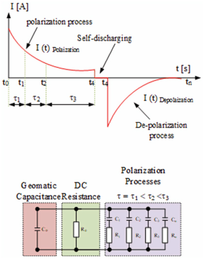
Figure 1 The polarization mechanism in the insulation material and the insulation equivalent circuit.
Table 1 The data of material applied for the stator insulation system
| Sections | Parts | Materials | Limit Temperatures |
| 1 | Conductor layer | Mica type and PET film | 155°C |
| 2 | Slot layer | Mica type and fibreglass | 155°C |
| 3 | Discharge Protection layer | Graphite conductive tape/silicon carbide tape | 155°C |
| 4 | Impregnation layer | Epoxy resin | 170°C |
The ambient relative humidity (RH) was around 60% throughout the testing period. The test sample is detailed in Table 2.
To perform the PDC measurement, a four-step procedure was followed:
Step 1: the remaining current of the stator winding insulation was measured before applying a test voltage into the test object.
Step 2: a DC voltage of 500 volts was applied to the test object for 1,000 seconds for polarization current measurement.
Table 2 The type of test sample under test
| Type I | Haft-Overhang Bar |  |
| Type II | Full Overhang Bar |  |
| Type III | Full Bar |  |
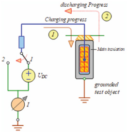
Figure 2 The experimental setup with the test sample for the PDC measurements.
Step 3: after polarization progress had finished the test object was allowed to self-discharge around 100 seconds before starting depolarization current measurement.
Step 4: the test object was short-circuited through the measurement circuit and the depolarization current was measured.
The PDCs were measured and recorded using a dielectric response analyser. The test apparatus is shown in Figure 2.
4 Results
This section presents the results obtained from the PDC measurement of each test object under room and operating temperatures. The experiment was conducted to study the effect of the thermal stress on the insulation system of the stator winding. The results are shown in Figure 3.
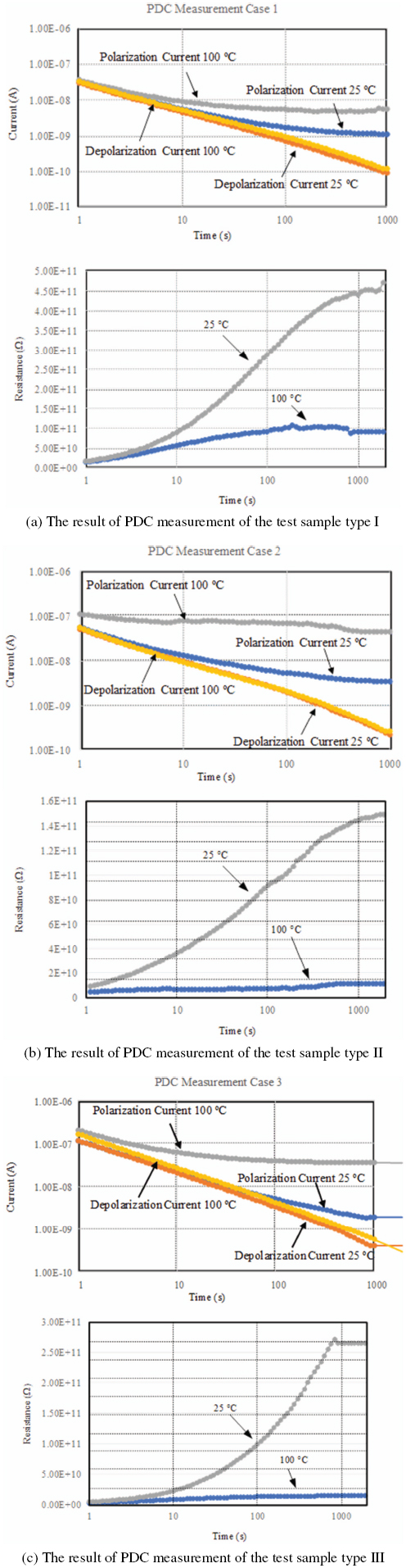
Figure 3 PDC measurement test results.
According to Figure 3, the PDCs of the test specimen without thermal stress measured at 25°C were lower than those of the test specimen subjected to 100°C thermal stress for all the cases. Besides, the resistance of the test specimen without thermal stress measured at 25°C was higher than those of the test specimen subjected to 100°C thermal stress for all the cases. Thermal stress could affect both the chemical and physical properties of the insulation. The chemical degradation would generate the mobility of the ions of the dipole, and the degree of the dipole orientation would be intensive. This was because the moisture was a reaction with the combination of the epoxy, glass and mica materials, which affected the interfacial polarization at the interface barrier within the insulation [12–19].
5 Discussion
The test results in the time domain are converted into the frequency domain for analysis purposes. Fourier transform and a curve fitting technique are used in this process. The Fourier transform is used for the complex capacitance approximation. The complex capacitance included with the real and imaginary capacitances can be calculated in the frequency domain as shown in the following equations:
| (3) |
| (4) |
The complex capacitance is composed of the following main parameters: C′(ω) is a real capacitance in the frequency domain, C″(ω) is an imaginary capacitance in the frequency domain, CGeo is the geometric capacitance and RiCi are the constants from the polarization losses.
According to Figure 4, it is assumed that when ω → 0 or with being a decreasing frequency, the complex capacitor is dominant by the geometric capacitor in an equivalent circuit. On the other hand, when ω → ∞ or with being an increasing frequency, the capacitance value reduces.
Consider the measured current in the time domain according to Equations (1) and (2), thus, the coefficients Ai and the time constants ti can be described with the polarization processes caused by the bulk relaxation insulation system. Different mechanisms were also characterized by the specific time constant, which depended on the stress parameters such as the temperature. The relationship between the charge and the measured current can be described as in the following equations:
| (5) |
| (6) |
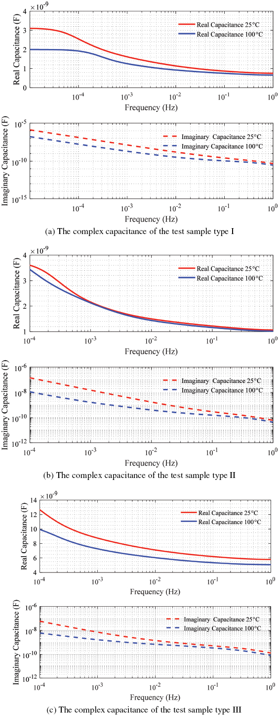
Figure 4 The results of the calculated complex capacitance.
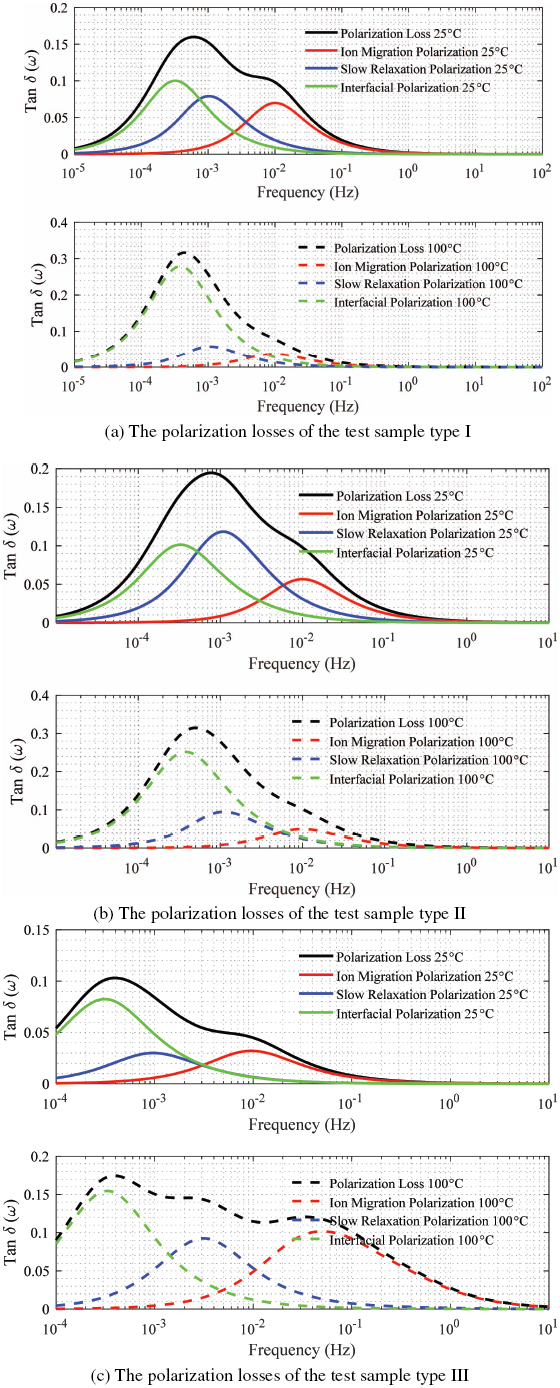
Figure 5 The time constant of test samples.
The time constants can be calculated by the following equation:
| (7) |
The equivalent circuits for modelling the stator winding insulation system have been proposed based on a simple RC model. This model consists of a parallel series of the resistor and capacitor as shown in Figure 1. Each subseries circuit of Ri and Ci represent a relaxation time constant given by ti = RiCi. This model may describe the winding insulation condition [20]. The constants t1, t2 and t3 represent the relaxation time constants of the polarization mechanisms related to the aging process within the insulation.
According to Figure 5, the time constants can be calculated by using a numerical method [21–23]. The results show that the polarization loss and t3 of the test specimen without thermal stress measured at 25°C were lower than those of the test specimen subjected to 100°C thermal stress for all the cases. The polarization loss occurring during the polarization process is caused by collisions and energy dissipation during the repetitive reorientation of the dipoles. Moreover, the t2 and the t1 are dependent on the insulation condition.
6 Conclusion
The insulation of the machine rated of 13.8 kV, which has a service life of more than 230,000 hours was used in the experiment. The experimental results show that the polarization currents changed when the test sample was aged due to the thermal stress. The complex capacitance and the polarization losses of the insulation system were calculated in the frequency domain. It was found that the complex capacitance and polarization losses of the insulation system depended on the insulation condition affected by the thermal stress.
As mentioned earlier, the proposed technique can be utilized for evaluating the condition of the insulation systems, which are beneficial for the maintenance planning of the machines used in industrial sectors, including machines used to support the communication systems. The insulation system of these machines needs to be in a healthy condition, i.e., it should not generate any noise signals to disturb the multimedia communication equipment during operation.
Acknowledgements
This work was supported by the King Mongkut’s Institute of Technology Ladkrabang Research Fund (Academic melting pot program 2018). The authors also gratefully acknowledge the support by the staff at the Dielectric Analytika Laboratory, KMITL.
References
[1] C. Sumereder, R. Woschitz and M. Muhr, “Condition evaluation of generator bars”, International Symposium on Diagnostics for Electric Machine, Power Electronics and Drives, Vienna, Austria, September, 2005
[2] C. Sumereder, R. Woschitz and M. Muhr, “Polarization-depolarization measurements at insulation systems for rotating machines”, International Symposium on Electrical Insulating Materials, Kitakyushu, Japan, June, 2005
[3] Supatra A. Bhumiwat, “On-site non-destructive dielectric response diagnosis of rotating machines”, “IEEE Transaction on Dielectric and Electrical Insulation Volume 17(5), pp. 1453–1460, October, 2010
[4] E. David, G. C. Stone, M. Sasic, “Dielectric response of machine insulation extracted from DC ramp test on individual stator bars”, IEEE Electrical Insulation Conference (EIC), Baltimore, USA, August, 2017
[5] P. G. S. Kumar, K. Kalyan Kumar, “Condition assessment program on aged high voltage insulation of in-service turbine generator”, International Conference on Control Communication and Computing India (ICCC), Trivandrum, India, March, 2016
[6] T. K. Saha, P. Purkait, “Investigation of polarization and depolarization current measurements for the assessment of oil-paper insulation of aged transformers”, IEEE Transactions on Dielectrics and Electrical Insulation Volume 11(1), pp. 144–154, February, 2004
[7] S. Daisy Flora, J. Sundara Rajan,. “Assessment of paper-oil insulation under copper corrosion using polarization and depolarization current measurements”, IEEE Transactions on Dielectrics and Electrical Insulation Volume. 23(3), pp. 1523–1533, August, 2016
[8] Anuradha Kumar and Satish M. Mahajan, “Time domain spectroscopy measurements for the insulation diagnosis of a current transformer”, IEEE Transactions on Dielectrics and Electrical Insulation Volume. 18(5), pp. 1803–1811, October, 2011
[9] Jing Xu and Bo Gao, “Research of aging status assessment of large generator winding insulation by polarization and depolarization current”, IEEE International Conference on High Voltage Engineering and Application (ICHVE), Chengdu, China, September, 2016
[10] E. Sacher, “Dielectric Properties of Polyimide Film. II. DC Properties”, IEEE Transactions on Electrical Insulation Volume EI-14(2), pp. 85–93, April, 1979
[11] Eric David, Reza Soltani and Laurent Lamarre, “PDC measurements to assess machine insulation”, IEEE Transactions on Dielectrics and Electrical Insulation Volume 17(5), pp. 1461–1469, October, 2010
[12] Reza Soltani, Eric David and Laurent Lamarre, “Impact of humidity on dielectric response of rotating machines insulation system” IEEE Transactions on Dielectrics and Electrical Insulation Volume 17(5), pp. 1479–146, October, 2010
[13] T. K. Saha, P. Purkait, “Understanding the impacts of moisture and thermal ageing on transformer’s insulation by dielectric response and molecular weight measurements”, IEEE Transactions on Dielectrics and Electrical Insulation Volume 15(2), pp. 568–582, April, 2008
[14] Reza Soltani, Eric David and Laurent Lamarre, “Impact of humidity on dielectric response of rotating machines insulation system”, IEEE Transactions on Dielectrics and Electrical Insulation Volume 17(5), pp. 1479–1488, October, 2010
[15] Z. Wang, Z. D. Jia, M. H. Fang and Y. S. Li, Z. C. Guan, “Moisture absorption, desorption, and moisture-induced electrical performances of high-temperature vulcanized silicone rubber”, IEEE Transactions on Dielectrics and Electrical Insulation Volume 23(1), pp. 410–417, March, 2016
[16] I. Fofana, H. Hemmatjou and F. Meghnefi, “Effect of thermal transient on the polarization and depolarization current measurements”, IEEE Transactions on Dielectrics and Electrical Insulation Volume 18(2), pp. 513–520, March, 2011
[17] Laurent Lamarre and Eric David, “Temperature dependence of the resistance of modern epoxy mica insulation of HV rotating machines”, IEEE Transactions on Dielectrics and Electrical Insulation Volume 15(5), pp. 1305–1312, October, 2008
[18] E. David, L. Lamarre and D. N. Nguyen, “Measurements of polarization/depolarization currents for modern epoxy-mica bars in different conditions”, Electrical Insulation Conference and Electrical Manufacturing Expo, Nashville, USA, October, 2007
[19] R. Neagu and E. R. Neagu “Analysis of relaxation parameters and their distributions using fractional polarization thermally stimulated discharge currents”, IEEE Transactions on Dielectrics and Electrical Insulation Volume 11(2), pp. 242–248, June, 2004
[20] G. Yianakopoulos, J. Vanderschueren, J. Niezette and A. Thielen, “Influence of physical aging processes on electrical properties of amorphous polymers”, IEEE Transactions on Electrical Insulation Volume 25(4), pp. 693–701, August, 1990
[21] Yasuhiro Matsuda, Yoshihiro Saito and Shigeru Tasaka, “Dipole polarization formed on surface of polypropylene electrets”, IEEE Transactions on Dielectrics and Electrical Insulation Volume 17(4), pp. 1015– 1020, August, 2010
[22] Bjoern Martin, Herbert Kliem, “Non-exponential polarization currents in solid electrolytes”, IEEE Transactions on Dielectrics and Electrical Insulation Volume 22(1), pp. 503–508, February, 2015
[23] Mahdi Shadmand, Hassan Moazami Goudarzi and Sedigheh Kazemi, “PDC characteristics of modern stator insulation systems”, IEEE 11th International Conference on the Properties and Applications of Dielectric Materials (ICPADM), Sydney, Australia, October, 2015
Biographies

Natthawut Phloymuk was born June 7, 1985. He graduated electrical engineering from the King Mongkut’s University of Technology North Bangkok. His employment experience ABB company, General Electric Company (GE) and Siemens Company. His special field of large machinery (motor, generator, wind turbine and gas turbine system). He is interest in research field of high voltage insulation characteristics and condition monitoring of large rotating machine. Currently, he is Ph.D. student at the Electrical Engineering Department, Faculty of Engineering, King Mongkut’s Institute of Technology Ladkrabang, Bangkok, Thailand.
Masaaki Kando (Fellow IEEJ, Life member IEEE) graduated from the Tokai University, Japan with M.Eng. degree in 1973. He joined the academic staff as an assistant professor of the Department of Electrical Engineering, Tokai University in 1973, lecturer in 1978, associate professor in 1985 and professor in 1992. He was awarded the Doctor of Engineer degree by the Nagoya University in 1991. He received the title of professor emeritus from the Tokai University in 2011. He is also an IEEE Life Member, IEEJ Fellow and IEEJ Life Member in 2014. He supported Malaysia – Japan Higher Education Program as an expert and lecturer under Malaysia Government, and other Asian universities (Thailand, Cambodia and Laos) in high-voltage engineering. Currently, he is a visiting professor of the KMITL in Thailand.

Norasage Pattanadech received his B.Eng and M.Eng degrees in electrical engineering from the King Mongkut’s Institute of Technology Ladkrabang in 1998 and Chulalongkom University, Thailand in 2002, respectively. He is also awarded a Ph.D. degree by the Institute of High Voltage Engineering and System Management, Graz University of Technology, Austria in 2013. Currently, he works as an associate professor at the King Mongkut’s Institute of Technology Ladkrabang, Bangkok, Thailand. His research activities have been mainly involved in partial discharge in insulating liquid, solid insulator characteristics and high-voltage testing.
Journal of Mobile Multimedia, Vol. 15_4, 339–356.
doi: 10.13052/jmm1550-4646.1544
© 2020 River Publishers