Low Cost Modular Actuator Fabrication with Aid of Additive Manufacturing, Utilizing Brushless D.C. Motor and Its Control Electronics for Robotics Application
Shashank Shekhar1, Usha Tiwari1,*, Manthan Gandhi1 and Shailendra K. Tripathi2
1Department of Electrical, Electronics and Communication Engineering, School of Engineering and Technology, Sharda University, Greater Noida, India
2Department of Physics and Material Science, Jaypee University, Anoopshahr, UP, India
E-mail: skrchem99@gmail.com; ushapant@rediffmail.com; manthangandhi92@outlook.com; shailendra.amu@gmail.com
*Corresponding Author
Received 08 January 2025; Accepted 01 May 2025
Abstract
This paper presents a method of fabricating a low-cost, low-complex Brushless D.C. Motor-based modular actuator for robotics application. A modular actuator using generic hobby brushless motors is fabricated with the aid of an additive manufacturing method (3D-Printing). This work inspects about designing and modification of an actuator. The prototype can be fabricated using 3D printing for a particular application. To test the working of the actuator and control mechanism Arduino UNO R3 and triple half-bridge motor driver I.C. (L6234D) is used. Further, advancements to implement Field Oriented Control are explored using ESP32S and a custom-made DRV8305 BLDC driver board along with an AS5147 absolute encoder. In contrast to costly actuators, additive manufacturing provides ease of in-house prototyping and modification.
Keywords: BLDC Motor, additive manufacturing, actuator, control system.
1 Introduction
The main feature of a robotic system includes its ability to move, navigate and interact with or manipulate objects in its surrounding. To implement this functionality robotic systems relies on actuators. Due to the high cost of actuators available for various robotic applications in humanoids, robotic arms, quadruped platforms, and other robotic systems, it is inaccessible to the student, academic scholars, and individual roboticists. Various low-cost options are available but they lack necessary form factor, torque output, R.P.M., back drivability [1], working voltage, and current requirements for a specific application; so unwillingly to get the desired outcome we are forced to use available alternatives and compromise with its design, working volume, structural integrity, aesthetics.
It never really works out up to the desired result, as there are always some flaws, whether it is due to the heavy & bulky design, unnecessary mass addition restricting work volume, or convulsive movement due to low torque output. The present-day hardware is often mechanically complex and costly to manufacture, also, the control electronics used is, not commercially available. To support rapid and broad progress in academic research, we believe hardware must be inexpensive and relatively easy to reproduce, and easily modified to required specifications. The programming environment, Arduino I.D.E. Which is open source can be used to program the motor driver and implement various control methods. Absolute encoder allows it to achieve the required velocity and precise position control. Further upgradation to ESP32, DRV8305 motor driver and AS5147 high-resolution rotary position sensor allow us to implement Field Oriented Control. It allows us to access the full capabilities and control over torque & speed directly based on the electromagnetic state of the motor.
This open-source and modular design allows one to modify a generic hobby brushless motor to a low-cost high-performance modular actuator. Towards these goals, we present a novel, open-source modular actuator that can be fabricated with the help of 3-D printing and its control System electronics.
2 Literature Survey
Species in their natural habitat have gone through evolution to inherit characteristic traits necessary for their survival. Over time, the mechanism of natural selection has made species, particularly in mammals to acquire a certain set of physiological features to sustain and manipulate their environment. The main challenge is to mimic and harness these features in bio-inspired Mechatronic systems to achieve high accuracy and in turn to utilize it for the improvement of existing robotics systems. A class of biolocomotion robotic systems is mobile (legged) robots, using leg instead of wheels provides superior mobility in natural terrain. It all boils down to actuators when it comes to articulated robots whether it be manipulators or mobile robots.
A dynamically running and leaping quadruped name Minitaur has been presented [2]. It utilizes T-Motor U series without any external reduction gear box. The major advantages include negligible backlash, high mechanical stiffness, high-bandwidth signal flow and significantly higher power than its geared counterparts. A major trade off for all these features is without a gearbox to amplify the torque and reduce speed is that the direct drive motors must operate at high torque and low-speed ranges due to which it produces a significant amount of heat. The dynamic quadrupedal robot utilized ANYdrive a series elastic actuator [3]. It comprises of high torque motors and harmonic drive gears in series with a rotational spring. The offset positioning of the actuator and its placement of the knee joint allow it to have a wide range of motion without any extra transmission.
Moreover, for dynamic robots, a hobby brushless motor and customize its frame in order to fit in a single stage planetary gearbox inside the space available in stator coil. Indeed, it an elegant design to mount the gearbox inside the starter coil [4]. It resulted in achieving required torque output in a compact form factor. The complexity of matching and cost of manufacturing is the major factor that determines the production feasibility of these type of actuators. An institution and facilities not having access to such industrial grade matching capabilities require a workaround to test their models even before investing a major part of their funding for a full scale prototype actuator fabrication. Further, a comprehensive review of quadruped robot’s legs according to their leg based on their degrees of freedom, along with various quadruped platforms discussed it shares a good amount of insight on actuator design parameters, working principle and capabilities [5].
3 Actuator Overview
This section details the base motor selection, actuator design, control electronics development. The mentioned norms can be easily modified for a specific use.
3.1 Base Motor Selection
An important aspect of Brushless motor Actuator systems is the base motor as it affects the design parameters and overall performance of the actuator. A critical metric of the brushless motor is the radius gap. Radius gap is the distance from the rotating axis to the centre of the gap between permanent magnets on the rotor and the stator coil. The radius gap is directly proportional to the torque density of a brushless motor [6]. Due to this, it is preferred to use a brushless motor with a can height (or length) less than its radius gap (or its diameter for approximations). In this work, we have used TAROT 4008 TL2955 330KV Martin Long Flight Time Brushless Motor it is used in agricultural drones as shown in Figures 1(a) and 1(b).
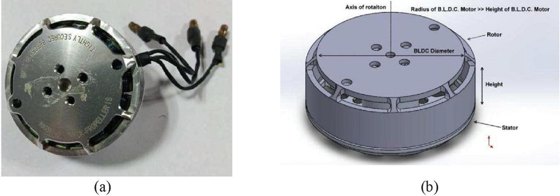
Figure 1 (a) & (b): TAROT 4008 TL2955 330KV Brushless Motor ; Radius and height comparison of B.L.D.C. Motor. Larger the radius larger the radius gap thus more torque density.
The axial length of the motor does not affect the torque density, it is the same as adding an identical motor along the axis of rotation. Another important aspect is the KV rating of the brushless motor, it is measured by the number of revolutions per volt; a lower KV B.L.D.C. is preferred as it has more torque output as a lower KV Motor has more winds of thinner wire so it will carry more volts at fewer amps of current thus having high torque constant.
3.2 Actuator Design
The actuator module consists of a two-stage planetary gear with a net reduction ratio of 9:1 (3:1 in each stage), the ring gear is modified to act as gear housing [7–9]. The output shaft is mounted on a 6810-2RS bearing for proper axial and radial load distribution. The actuator design assembly is illustrated in Figure 2(a). Most of the parts, planet gear, sun gear, ring gear, output shaft, planet carrier, and the motor mount is fabricated with the help of additive manufacturing method. Parts are printed on the Ender-3 3D printer. Planet, Ring, and Sun gears are printed in P.E.T.G. (Polyethylene terephthalate glycol) that provides impact resistance, high strength, and durability as presented in Figure 2(b). The weight of the total actuator assembly is 486 grams.
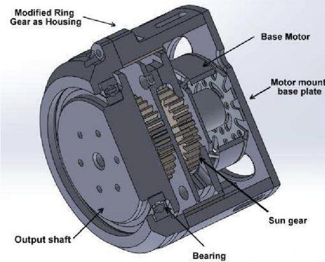
Figure 2(a): Section view of actuator design assembly.
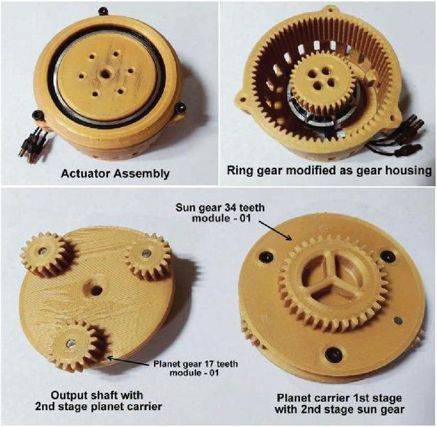
Figure 2(b): Actuator assembly and internal 3D printed parts.
The nozzle diameter used is 0.2 mm for better layer adhesion and a smooth surface finish, it is advised to print with 60%–100% infill selection and better to avoid print orientation where the support structure is added to achieve a better surface finish. To stop curling or warping due to shrinkage at the sharp corners adhesion should be enabled in print settings. A test prototype that is fabricated as a proof of concept, further enhancing the robustness and ease of use of a smaller version of the actuator developed [10]. A smaller gear module of 0.7 is used that results in a size reduction of 54.71% of the previous version as represented in Figure 2(c). Also, this test actuator is much lighter, 196 grams. Size reduction allowed to save excess material and weight and still providing the same torque output as the reduction ratio was still kept to 9:1 as in the previous version. A major issue of airflow is also resolved. Keeping the motor mount as open as possible without compromising its strength. All the parts are aligned and fastened with three 55 mm M5 bolts.
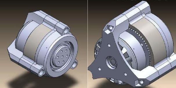
Figure 2(c): Improved design of actuator with the 0.7 gear module.
For continuous operation of the actuator, rising temperature is a major issue, even with a smooth surface finish of gear teeth, friction comes into play in the long run [11]. To avoid such issues, lithium-based grease was applied to the matting gear sets, this allowed smooth functioning. This also leads to significant noise reduction. A design of shape memory alloy based 4D-printed actuator is reported in [17] and Aerospace Actuator Manufactured by Laser Powder Bed Fusion is presented in [18].
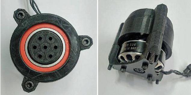
Figure 2(d): Improved actuator assembly.
The improved actuator assembly is much more compact than the previous design and can be modified to be mounted with other links to form the structure of a robotic system which is given in Figure 2(d). For a robotic joint torques are converted into desired motor current using the relationship where is torque constant and for TAROT 4008 TL2955 330KV Martin Long Flight Time Brushless Motor the N m/A. As a mentioned reduction ratio of the gear N 9; which leads to . For an input current (), say 10 A, Nm will be the maximum output torque. Its design can be easily modified to best suit the needs, it can be used to fabricate sophisticated robotic manipulators.
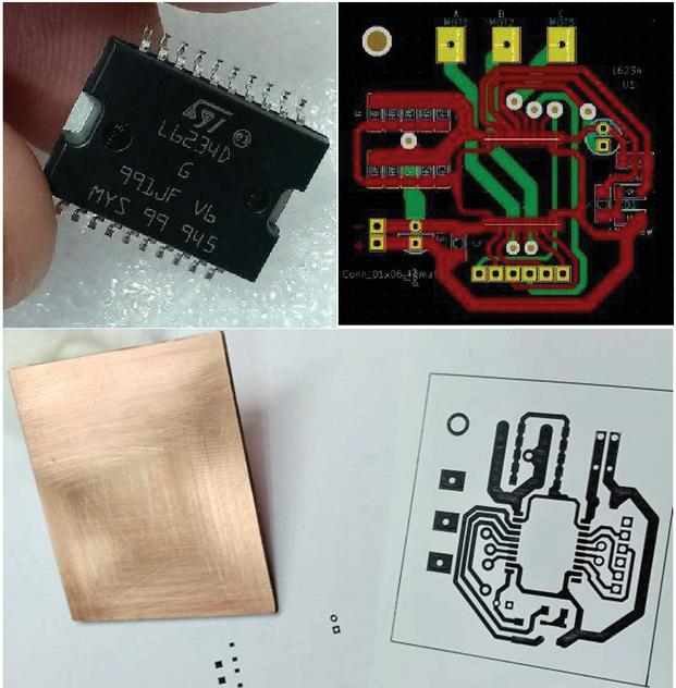
Figure 3(a): L6234D Motor driver I.C., Motor driver P.C.B. Layout P.C.B. fabrication using toner transfer method.
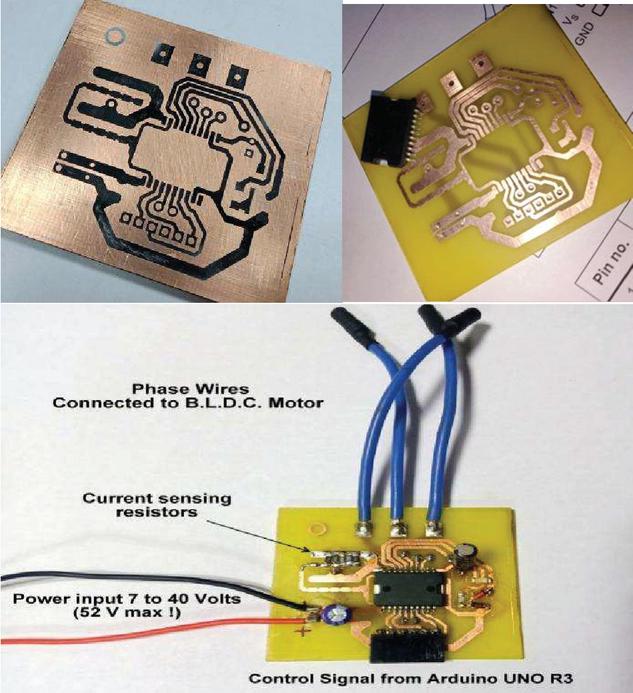
Figure 3(b): Double sided Copper Clad board with Circuit layout before etching, P.C.B. after etching with FeCl, Final Circuit board with all the components soldered.
3.3 Control Electronics
Control Electronics is kept relatively simple to test various control parameters. The L6234D triple half-bridge is used to drive the brushless motor. Supply voltage ranges from 7 to 52 V with a maximum current of 5 A. The control signal to each half-bridge of the L6234D was provided by an Arduino UNO R3. The L6234D motor driver I.C. requires few passive components so as per its datasheet we have designed and fabricated a two-layer P.C.B.(Printed Circuit Board) and soldered the required components which is depicted in Figures 3(a) and 3(b).
The motor phase traces width is 2 mm and kept on the bottom layer of the P.C.B. to isolate it from the rest of the circuit. The current sensing resistors consist of four 1 ohm resistors in parallel.
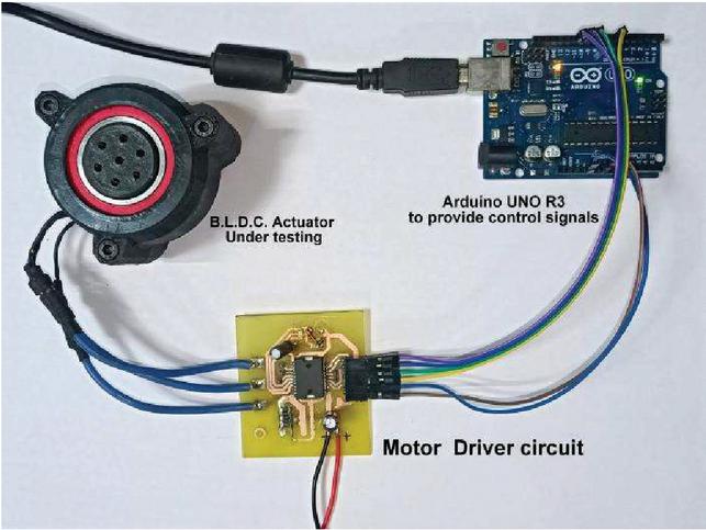
Figure 3(c): Actuator Test setup using Arduino UNO R3 and L6234D motor driver circuit.
Arduino provides the P.W.M. signals to L6234D I.C. to test the actuator. L6234D I.C. is used for testing purposes only, for higher rating motors, more current is needed for required torque so it is advised to use a proper rated B.L.D.C. motor driver as shown in Figure 3(c). Additionally, external encoders should be used instead of back E.M.F. for determining the position of the rotor precisely.
4 Position Sensing Using AS5147
The motor driver L6234D allows to have basic control, but the implementation of position, velocity, and torque can be accessed in addition to a high-resolution rotary position sensor. Here AS5147 absolute magnetic encoder is used, it has a standard 4-wire SPI serial interface that allows a host microcontroller to read 14-bit absolute angle position data from the AS5147 sensor. We made a breakout board for sensing.
Figure 4(a): AS5147 breakout board with power indicator led, “diametrically-magnetized” magnet to sense rotor position.
To sense the rotor position a “diametrically-magnetized” magnet is used, over which AS5147 is mounted with help of screw inserts inserted on actuator base plate. Diametrically-magnetized magnets have the poles on opposite sides of their diameter, making them perfect for magnetic angle and rotation sensing. Figure 4(a) shows the AS5147 breakout board with power indicator led and Figure 4(b) presents AS5147 breakout board mounting the actuator back plate. The air gap between encoder and magnet should be 2 mm to 3 mm for accurate and reliable readings.
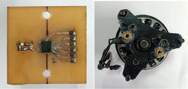
Figure 4(b): AS5147 breakout board mounting the actuator back plate, close up view of encoder above diametric magnet.
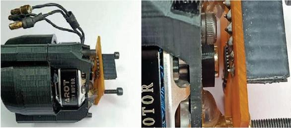
Figure 5 (a) & (b): DRV8305 Motor Driver Board ; Basic Setup of ESP32S, DRV8305 Motor Driver and AS5147 encoder mounted on an actuator back plate.
5 DRV8305 Motor Driver Board
Motor controller is an important aspect of an actuator as it determines the over all functionality and performance, the DRV8305 device is a gate driver IC for three-phase motor-drive applications [12, 13]. The device provides three high-accuracy and temperature compensated half-bridge drivers, each capable of driving a high-side and low-side N-channel MOSFET. The allowed supply voltage is 4.4V to 45V and provides 1.25 A and 1 A peak gate driver currents. For high current handling capabilities, six of BSC022N04LS N-channel power MOSFET in are used in 3 half-H bridge configurations. The BSC022N04LS MOSFET is capable of handling 134A of continuous drain current (at V, C) with a safe operating voltage of 40 volts which is more than enough to drive even bigger BLDC motors which is illustrated in Figures 5(a) and 5(b). In addition to these three 2 milliohm, current sensing resistors are used to measure current in each phase.
6 Third Iteration and Testing of Additively Fabricated Actuator
After several testing & debugging we proceed to implement the design concept for prototyping actuators for a quadruped robotic platform like quadrupedal and bipedal robotic platform application. This iteration of the actuator utilizes the ex8108 B.L.D.C. motor as the base motor and the fabricated DRV8305 motor driver board. Figures 6(a) and 6(b) present the actuator iteration design and ex8108-105KV B.L.D.C. respectively. To measure the feasibility and performance of the fabricated actuator, as a control test example, we compared its torque output with GIM8008 which is widely used actuator in quadrupeds and bipedal robots.
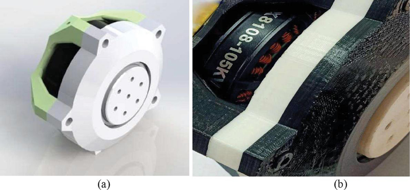
Figure 6 (a) & (b): Actuator Iteration Design; ex8108-105KV B.L.D.C. as base motor.
It is evident from Figures 6(c) and 6(d) that the actuator fabricate is of the same form factor as that of GIM8008 actuator. The cost of fabrication of a 3D Printed actuator is also significantly lower, approximately four times less in comparison to the GIM8008 Actuator (acquired from online sources for testing purposes) with really competitive performance.
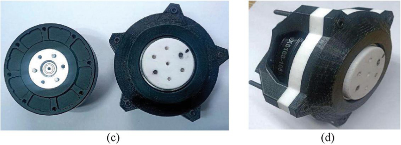
Figure 6 (c) and (d): GIM8008 (Left) & 3D Printed Actuator with ex8108 B.L.D.C. Motor (Right); 3D Printed Actuator with ex8108 B.L.D.C. Motor.
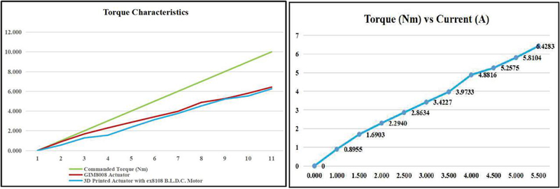
Figure 6 (e) & (f): Torque Characteristics of GIM8008 Actuator (Red) & 3D Printed Actuator with ex8108 B.L.D.C. Motor (Light Blue); GIM8008 Actuator Torque (y-axis) vs Current (x-axis) curve.
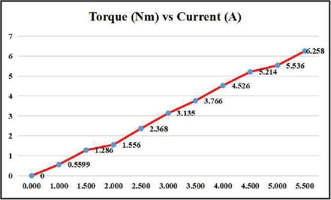
Figure 6 (g): 3D Printed Actuator with ex8108 B.L.D.C. MotorTorque (y-axis) vs Current (x-axis) curve.
Various tests have been conducted at a constant input voltage of 24 volts and various characteristic plots were deduced. It is evident from the Figures 6(e), 6(f), and 6(g) and that the performance of the actuator fabricated using the 3D printing technique is somewhat similar to that of GIM8008 actuator. To further validate our findings, we concluded to build a robotic system using the 3D printed actuator. Initially, our aim is to build a robotic manipulator which can perform complex manoeuvre and after some modification we are looking forward to implement it in a quadruped robotic platform.
7 Control Implementation
The control hardware for the actuator including a motor driver board, encoder and a microcontroller unit. The simple F.O.C. (Field Oriented Control) [14] library provided by the Arduino environment is used to implement open and closed-loop control while having complexity in case of closed-loop control it is easily resolved by the simple F.O.C. library as it provides us predefined function rather than having complex blocks of code. A significant feature it has to offer is P.I.D. control in a closed-loop mechanism to achieve the desired system output is crucial for robotic joint application where precise control over velocity, torque, and position is required. Input values of operating voltage, the number of pole pairs, maximum allowed current is required while using a particular type of BLDC motor. The only difference is between the power handling capabilities and the feature provided by the motor driver where it is usually observed to have access to more features at a high cost. Figure 7 shows the mechanism of control algorithm.
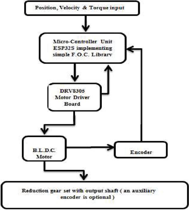
Figure 7 Block diagram of control algorithm.
8 Additive Manufacturing Norms for Actuator Fabrication Control Implementation
Actuators fabricated by additive manufacturing have their advantages over conventional actuators such as low cost, low weight, high degree of customization according to requirement, etc. It is suitable for test prototyping purposes. A unique advantage is its flexibility in manufacturing systems [15] as a single unit rather than separate parts and thus leads to having less number of parts required, two or more joining links can be merged which is not conventionally feasible.
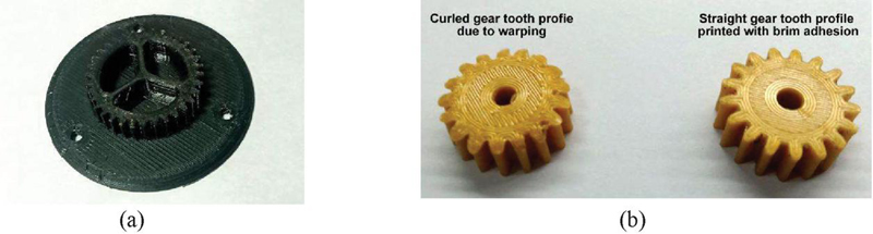
Figure 8 (a) & (b): Second stage sun gear merged with first stage planet carrier allows to have reduced no. of joining links ; Bottom View before and after build plate adhesion.
The modification allows have flexibility of design and over-all mechanical properties. Control over properties like face width, pressure angle, module, hub type or shaft diameter, etc. allows us to save cost when there is the unavailability of a specific part. As one can modify the design and avoiding to purchase an alternate part. A key factor is cost reduction with 3D printing, whereas one needs to go through the various manufacturing process to get a custom-designed part which increases the cost for a prototype. Additive manufacturing has its complexities when it comes to the application [16], a major issue is curling or warping of sharp corners. The sharp corner leaves the build plate while printing is still in progress, this gives a curled look facing inwards. While printing planet gear the problem of curling is encountered and solved by adding build plate adhesion as illustrated in Figures 8(a) and 8(b). There are three types of build plate adhesion namely skirt, brim and raft. We have utilized brim as adhesion to counter the issue of warping.
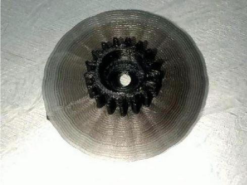
Figure 8 (c) Brim build plate adhesion.
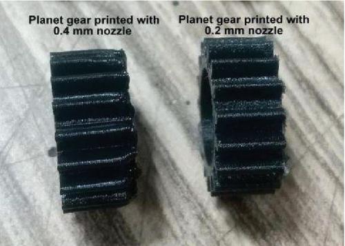
Figure 8 (d) Planer gear print in different nozzle sizes.
Another important aspect of 3D printing of gear set assembly is to have a smooth surface finish of parts to reduce friction. The nozzle hole diameter of 3D printer can be changed to various sizes to obtain required quality of the part. A larger diameter may accelerate the manufacturing but does not provide a smooth surface finish. Smaller diameter nozzle do takes more time than the larger ones but can provide a smoother surface finish and better layer adhesion. To print gears, 0.2 mm diameter nozzle was used and resulted in a better surface finish than a 0.4 mm nozzle which was previously used as shown in Figures 8(c) and 8(d). Layer height settings can be modified to merge two layers farther than generally required, for better adhesion to increase its resistance to shearing loads on the gear tooth profile.
9 Limitations & Future Scope
The limitation of work is the wear and tear action of moving gears that leads to reduced life, when subjected to large forces and varying temperature changes gear tooth is expected to deform and lose its original profile. A detailed thermal and stress analysis is necessary for prolong use to have desired life. Additive manufacturing allows us to more customizable and adaptable parts whereas it lacks high material selection. Further development and advances may allow for a wider range of materials to be used in the additive manufacturing process, this will lead to greater control over varying characteristics and desired mechanical properties of manufactured parts.
10 Conclusion
This work presents a low-cost actuator module and design parameters for reproducing actuator parts with the process of additive manufacturing. A rather low-cost and effective method to fabricate Brushless Actuator for robotics application is introduced. Key parameter and marker of successful experiment is matching of torque characteristics of fabricated actuator to the commercially available one while keeping the form factor similar. Keeping a wide range for modularity and Various aspects of printing methods and settings are mentioned to achieve better quality parts. There is a significant cost reduction of approximately one fourth to that of the same configuration of commercially available actuator .The major problem of development cost for sophisticated and precise robotics systems such as robotic arm, legged robots is addressed in the following manner. It is anticipated that this work will benefit the robotics community by lowering the barrier of cost and lead to further development of low-cost actuators.
“Compliance with Ethical Standards”
(1) Disclosure of potential conflicts of interest: No Financial and non-financial competing interest. My research is not funded by any funding agency
(2) Research involving human participants and/or animals: I hereby declare that no human and animal are involved directly or indirectly in my research.
(3) Informed consent: I hereby declare that this study does’t include any clinical trials. No database is used in my research.
References
[1] Tatsuzo Ishida, Atsuo Takanishi. (2006). “A Robot Actuator Development With High back drivability”; IEEE Conference on Robotics, Automation and Mechatronics.
[2] G. Kenneally, A. De and D. E. Koditschek, “Design Principles for a Family of Direct-Drive Legged Robots,” in IEEE Robotics and Automation Letters, vol. 1, no. 2, pp. 900–907, July 2016.
[3] Hutter M, Gehring C, Jud D, et al. (2016). ANYmal – a highly mobile and dynamic quadrupedal robot. In IEEE/RSJ international conference on intelligent robots and systems (IROS 2016), Daejeon, South Korea, 9–14, pp. 38–44. USA: IEEE.
[4] Benjamin G. Katz. (2018). A Low Cost Modular Actuator for Dynamic Robots, Massachusetts Institute of Technology.
[5] Yuhai Zhong, Runxiao Wang, Huashan Feng and Yasheng Chen. (2019) Analysis and research of quadruped robot’s legs: A comprehensive review, International Journal of Advanced Robotic Systems: I–15.
[6] Sangok Seok, Albert Wang, David Otten and Sangbae Kim. (2012). Actuator Design for High Force Proprioceptive Control in Fast Legged Locomotion”, IEEE/RSJ International Conference on Intelligent Robots and Systems Vilamoura, Algarve, Portugal.
[7] Crispel S, Garcia PL, Saerens E, Varadharajan A, Verstraten T, Vanderborght BA, Lefeber D. (2021). A Novel Wolfrom-based Gearbox for Robotic Actuators. IEEE/ASME Transactions on Mechatronics.
[8] Matsuki H, Nagano K, Fujimoto Y. (2019). Bilateral drive gear – a highly backdrivable reduction gearbox for robotic actuators, IEEE/ASME Transactions on Mechatronics. 24(6):2661–73.
[9] Jonathan Terfurth and Nejila Parspour. (2019). Integrated Planetary Gear Joint Actuator Concept for Wearable and Industrial Robotic Applications, Wearable Robotics Association Conference (WearRAcon) Scottsdale, AZ, USA.
[10] Pablo López García, Stein Crispel, Elias Saerens, Tom Verstraten and Dirk Lefeber. (2020). Compact Gearboxes for Modern Robotics: A review, Front. Robot. AI.
[11] YeZhang, Chris Purssell, Ken Mao. (2020). “A physical investigation of wear and thermal characteristics of 3D printed nylon spur gears”, Simon Leigh Tribology International, Volume 141, 105953.
[12] Choi, Dongil. (2020). “Development of Open-Source Motor Controller Framework for Robotic Applications.” IEEE Access 8, 14134–14145.
[13] Motor Driver Architectures & Driver: DRV8x Family. (2020). Brushless-DC Motor Drive Considerations and selection guide”, from Texas Instruments, SLVAES1.
[14] Arduino Simple F.O.C., https://docs.simplefoc.com.
[15] Rengarajan Srinivasana, Vaggelis Giannikas, Duncan McFarlane, Alan Thorne. (2018). Customising with 3D printing: The role of intelligent control; Computers in Industry Volume 103, Pages 38–46.
[16] Tuan D. Ngo, Alireza Kashani, et al. (2018). Additive manufacturing (3D printing): A review of materials, methods, applications and challenges, Composites Part B: Engineering, Volume 143, Pages 172–196.
[17] Aryaman J. Singh, Siddharth Wala, Saiyadali H. Ladakhan, Rakshith B. Sreesha, Somashekara M Adinarayanappa, Design and fabrication of shape memory alloy based 4D-printed actuator for FWMAV: A performance study, Materials Today: Proceedings, 2023.
[18] Lizarribar B, Prieto B, Aristizabal M, Martín JM, Martínez-Iturralde M, San José E, Golvano I, Montes S. Electric Aerospace Actuator Manufactured by Laser Powder Bed Fusion. Aerospace. 2023; 10(9):813. https://doi.org/10.3390/aerospace10090813.
Biographies

Shashank Shekhar is an aspiring Roboticist with a degree in Electronics and Communication Engineering from Sharda University. He thrives on tackling complex, high-power, and ambitious problems, particularly those involving autonomous systems with unique approaches to dynamics and control. His interests span Collaborative Robotic Manipulators, legged robotics, and autonomous electric vehicles. Currently, he is working as an Electronics Engineer at Orangewood Labs Inc., in embedded hardware design, focusing on schematic capture, circuit design, simulation, and prototyping.

Usha Tiwari (Senior Member, IEEE) is currently Assistant Professor, Department of EECE, Sharda University. Dr. Tiwari is Ph.D. from Jamia Millia Islamia, New Delhi, in Data Compression Schemes for Wireless Sensor Networks. She did M.Tech in Electronics & Communication from MDU Rohtak in year 2010. Dr. Usha graduated with honours from UPTU Lucknow, Uttar Pradesh in 2005, with a degree in the field of Electronics & Instrumentation Engineering. She is holds the 8 th rank in top ten merit list declared by UPTU in 2005.

Manthan Gandhi, an EECE graduate from Sharda University, is a Project Engineer at SPACE India, overseeing the construction of a revolutionary observatory dome. This unique design boasts a 270-degree opening, a world first. During his engineering studies, Manthan worked on numerous projects, including his final year focus on an upper limb exosuit for motion amplification and rehabilitation.

Shailendra K. Tripathi, (Senior Member, IEEE), has completed B.Sc. and M.Sc. (Goldmedalist) from CSJM University Kanpur. He has done M.Tech. (Electronics Engineering) from Aligarh Muslim University, Aligarh. Dr. Tripathi earned his Ph.D. in Electronics & Communication Engg., from Malaviya National Institute of Technology, Jaipur in 2019. He has fourteen years of experience in teaching and research. He has published more than 25 Scopus/peer reviewed papers. Additionally, Dr. Tripathi has contributed 2 granted patents, 1 book and 5 book chapters. He is a senior member of IEEE and life member of Material Research Society of India.
Journal of Mobile Multimedia, Vol. 21_3&4, 693–712.
doi: 10.13052/jmm1550-4646.213420
© 2025 River Publishers