Design of Four-Core Uncoupled Multicore Fiber for Next-Generation Inter-Data Center Networks
Jirasak Ponchua1,* and Suchada Sitjongsataporn2
1The Electrical Engineering Graduate Program, Faculty of Engineering, Mahanakorn University of Technology140 Cheumsamphan Rd., Nongchok, Bangkok, Thailand
2Department of Electronic Engineering, Mahanakorn Institute of Innovation (MII)Faculty of Engineering, Mahanakorn University of Technology140 Cheumsamphan Rd., Nongchok, Bangkok, Thailand
E-mail: jirasak_ponchua@hotmail.com; ssuchada@mut.ac.th
*Corresponding Author
Received 27 June 2021; Accepted 02 August 2021; Publication 27 October 2021
Abstract
The increasing demands within and between the data centers used for data traffic has required. Efficient links are important to data center applications for supporting the unlimited demand. Transmission capacity of single-mode fiber (SMF) is limited by fiber nonlinearity which prevents the increasing transmission power and finite amplifier bandwidth. Single-mode multi-core fibers (SM-MCFs) that are expected to overcome the current limitation of optical communication capacity. However, the inter-core crosstalk still has an effect on SM-MCF, which can limit the transmission of the inter-data center. In this paper, the design of four-core uncoupled multicore fiber is discussed for next generation inter-data center networks in order to support the unlimited use of data traffic in the future. The objective of this paper is to determine the appropriate range of core radius and core pitch, which are taken into consideration to reduce the inter-core crosstalk inside the optical fiber. These parameters can be able to improve various constraints to achieve the best multi-core fibers design. From the simulation concerned with the inter-core crosstalk, the experiment results show that the range of core pitch is at 47.5 m to 50 m and the range of core radius starts from 4.5 m to 5.5 m, that can achieve with crosstalk lower than – 30 dB/100 km for the future inter-data center networks.
Keywords: Inter-data centers, single-mode fiber, single-mode multi-core fibers, inter-core crosstalk.
1 Introduction
Nowadays, the number of the data center around the world will increase. Data-center IP traffic to the other data center is expected to quickly increase [1]. Nevertheless, the limited bandwidth and optical amplification are the limitations of the transmission system. The power from the fiber non-linearity is an increase in the transmission capacity. Currently, the standard of single-mode fiber (SMF) uses a single core fiber surrounded by 125 m [2–5] and cladding surrounded by additional coating with many additional layers of environmental protection. With the limited space of fiber cables [6], the researchers have provided an increase capacity in per-fiber and then have turned to expansion into the spatial domain [3, 4], which have used either multiple cores sharing with the same cladding or increasing the core diameter to allow the transmission of multiple modes. Perhaps, an increase of the number of cores in the cladding is the simplest approach to achieve higher capacity but inter-core crosstalk (XT) is the most important parameter of multi-core fiber (MCF) concerned with. MCF can be divided into two groups; by spacing between the cores called ‘core pitch’, as the uncoupled MCF with the core pitch higher than 30 m and the coupled MCF with the core pitch lower than 30 m [2–5]. XT is brought by the mode-coupling, power-coupling between cores and places. The limits on how closely cores can be spaced leading to larger cladding diameters. Increasing the cladding diameter results are in the mechanical strength degradation of optic fiber. Furthermore, the other parameters as refractive index also need to be taken into the account.In this paper, the design of four-core uncoupled MCF is considered with the significantly low XT following the optic fiber parameters as core radius and core pitch in order to reduce the XT for the efficient transmission of the inter-data center networks.
2 Data Center Networks
The traditional data center architecture can be showed in Figure 1 [10, 11], which consists of three connection layers. In this architecture, the server connects to the access switch and then connect with two routers for redundancy. The traffic from one server to another in the same data center may travel up to the core layer and back down by traversing two access switches, two aggregation routers, and then a core router.
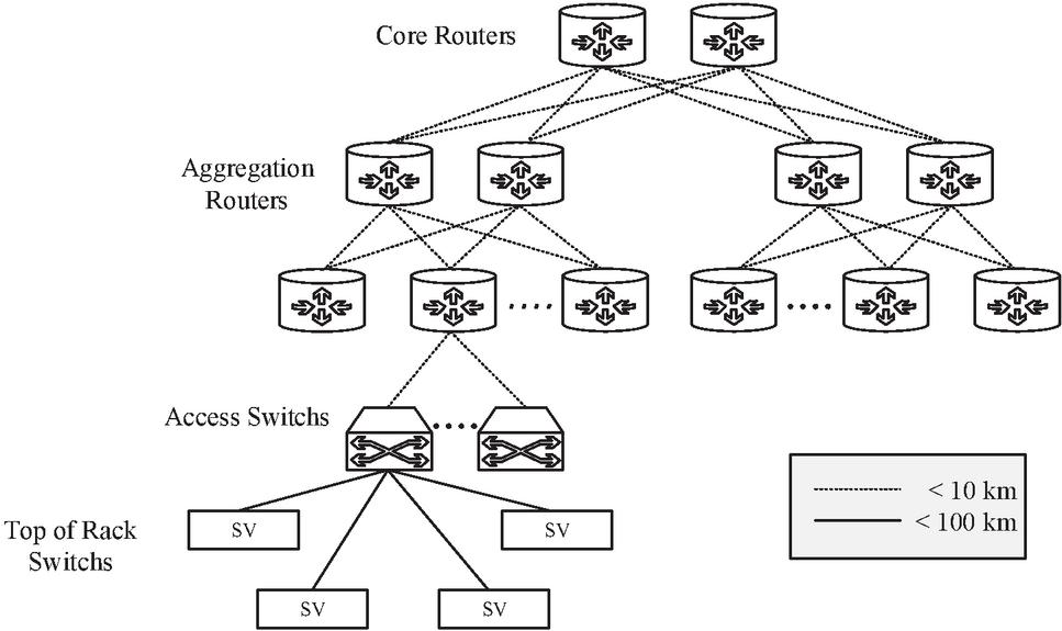
Figure 1 A traditional architecture of three connection layer of data center.
We can divide the connection characteristics of the data center into 2 levels [10, 11] as the intra-data center and inter-data center links. Figure 2 shows the intra-data center links system that consists of transceivers, multiplexer (MUX) and demultiplexer (DE-MUX) within the module. The transceivers of this links can use the multiple wavelengths to achieve high bit rates. The intra-data center links reach up to 10 km and typically operate at 1310 nm in order to minimize the total chromatic dispersion (CD). Figure 3 shows the inter-data center links system that can reach up to 100 km and operate at 1550 nm to leverage on the erbium-doped fiber amplifiers (EDFAs). CDs are important and must be compensated.
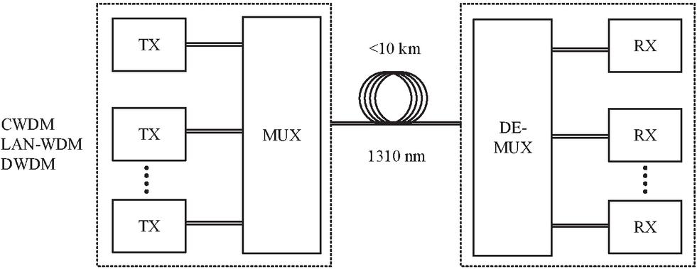
Figure 2 Intra-data center links.
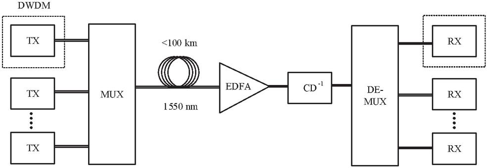
Figure 3 Inter-data center links.
As stated to the links between the inter-data centers, the dispersion corresponds to the residual CD after the optical CD compensation. The EDFA corresponds to an equivalent optical amplifier whose noise figure depends on the number of amplifiers in the link and on their individual noise figures. The performance can quantify in terms of the Optical signal-to-noise ratio (OSNR) to achieve the target of bit error rate (BER).
In this paper, we focus on the connection between the inter-data center with the smooth data transmission and low loss. These will increase efficiency and reduce network construction costs.
3 Multi-Core Fibers (MCFs)
MCF is an optical fiber with multi-cores in one cladding. The design of MCFs consists of a number of cores, the main core layout, the thickness of the outer cladding, and the diameter of cladding surrounded by 125 m [9, 12, 13]. The core pitch (CP) is the homogeneous properties [14] of the MCF, which is the distance between the neighboring cores as shown in Figure 4.
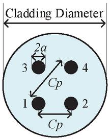
Figure 4 Single-mode four cores fiber with a square layout.
In Figure 4, the single-mode four-core fiber is presented with a square layout and each core will use the individual waveguide. The weakly-coupled MCF XT is an important problem. In order to optimize the design structure for single-mode four-core fiber and the crosstalk analysis, the different fiber parameters as core radius (), core pitch (CP) and relative refractive index difference are investigated. Different fiber design parameters and the corresponding values are shown in Table 1.
Table 1 Parameters of single-mode four-core fiber with a square layout
| Parameter | Value(s) | Unit |
| Core radius | 4.5, 4.75, 5, 5.25, 5.5 | m |
| Core pitch (between core #1 and core #2) | 40, 42.5, 45, 47.5, 50 | m |
| Core pitch (between core #1 and core #4) | 80, 85, 90, 95, 100 | m |
| Fiber bending radius | 142 | mm |
| Fiber length | 100 | km |
| Cladding diameter | 125 | m |
| Wavelength | 1550 | m |
4 Inter-core Crosstalk (XT)
Inter-core crosstalk (XT) can be defined as the interference caused by the magnetic field or electric field of a single-core signal that can affect the signal of adjacent cores. Since there are multiple cores in the same cladding area and the crosstalk, which is the important factor for the system [2, 14]. To reduce crosstalk (XT) between cores, the core pitch should be appropriate. In [14, 15], the MCF-XT can be predicted and calculated using a simple mode-coupling equation in the initial stages of MCF and development process. However, after the production and evaluation of the MCF prototypes, the researchers found that the predictions did not occur and due to the effects of bending in fiber and proved that the coupling equation was affected by bends and twists inside the fiber. This can accurately predict and use for the actual MCF-XT [14, 16]. When an optical fiber has a bend radius of , the refractive index distribution of the optical fiber can equivalently represent the elongation of the outer optical path of the bend as the tilted refractive index shown in Figure 5 [5].
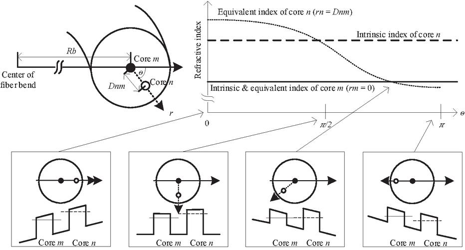
Figure 5 Equivalent refractive index of MCF affected by bend and twist. (Upper left) Parameters relating to bend in MCF. (Upper right) Equivalent effective refractive indexes of two cores. (Lower) Relative positions and equivalent refractive index distributions of two cores. (The line drawn across a core represents the height of equivalent effective refractive index.) [5].
Using core as a reference, the equivalent of core () is expressed as follows.
| (1) |
where is the distance between the center of core and the center of core . is the intrinsic effective refractive index of core and is the angle that has core and core form with respect to the direction of the bend radius. If an MCF is straight, its cores differ in effective refractive index phase matching does not occur.
The XT between two neighboring cores is shown in Figure 6, that is expressed in terms of the power signal. That is an amount of the optical power signal transmitting through the one core. There are coupled with its neighboring cores during signal propagation.

Figure 6 Power coupling from the input core to the neighboring core.
The XT between two neighboring cores can be stated as [1, 11]
| (2) |
where and is output power from core and from neighboring core .
The expression for average crosstalk ) between two neighboring cores in MCF can be simplified as [17]
| (3) |
where and are core numbers, and are the power and mode coupling coefficient respectively between core and core . is fiber bending radius. is fiber length and is mode propagation constant, where . Wave number is equal to , where is wavelength of light in vacuum and is the fixed constant at 1.452298 [18].
The mode coupling coefficient for two neighboring cores can be expressed as [18, 19]
| (4) |
and
| (5) | |
| (6) | |
| (7) |
where is a core radius, and is the modified Bessel function [19]. The expression of average crosstalk depends on average crosstalk on the mode coupling coefficient, fiber bending radius, fiber length, and core pitch.
5 Proposed System
The transmission system of the inter-data center plays an important role, while the increased bandwidth demand causes an expansion of the communication system. The flexible bandwidth of the transmission network has the capability of wavelength channels according to the user demands. In order to solve these problems above, we propose a design of four-core MCF as explained in Section 3 based on the inter-data center transmission system as described in Section 2.
The proposed connections of system are shown in Figure 7. The main connection system is still using the same traditional technology with the inter-data center transmission system. For the transmission, the signal to MCF four-core still uses MUX but requires modification of the working process to support it.
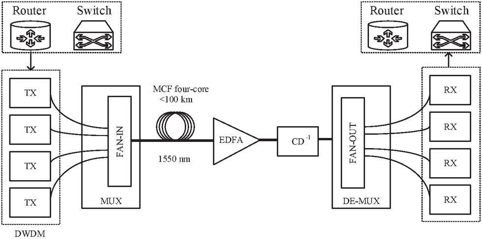
Figure 7 Proposed inter-data center transmission system.
As shown in Figure 7, the four-core MCF connection between the inter-data center should be around 100 km, which MCF expands the transmission system to be more effective without having the extra-investment. This can increase the transmission bandwidth developing by signal processing system. About the EDFA corresponds to an equivalent optical amplifier whose noise figure depends on the number of amplifiers in the link and on their individual noise figures. The dispersion corresponds to the residual CD after optical CD compensation. Finally, the performance of proposed system is quantified in terms of the OSNR to achieve the target BER as the same traditional technology. The main purpose of this research is to determine the optimal value of different fiber design parameters to achieve the target XT level equal to 30 dB/100 km or even less. The various core radius and the distance between core pitch are considered for the analysis of crosstalk diffusion.
6 Experimental Results and Discussion
In this section, we conduct the experiments to determine a suitable value of four-core MCF on various variables. The experiments are to determine the effect of inter-core cross-talk of core#1 and core#2, of core#1 and core#4 compared with the different of core pitch and core radius as follows:
According to Figure 4, the inter-core cross-talk of core#1 and core#2 compared with the various core radius are simulated with the different values of the parameters used in Table 1.
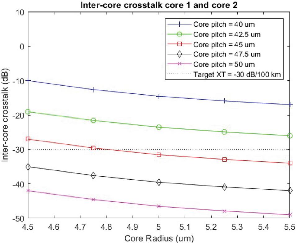
Figure 8 Inter-core crosstalk by different core radius (core#1 and core#2).
For crosstalk (XT) is the most important parameter of MCF. The conventional coupled mode and coupled power are used for XT analysis with the different fiber design. From the experimental result in the first step, Figure 8 shows the XT variation between core#1 and cores#2, when the core pitches have the different values. For the small core pitch at 40 m and 42.5 m, the crosstalk between two neighboring-cores is decreased when increasing the core radius. For larger core pitch 47.5 m and 50 m, the XT has under 30 dB/100 km upon used core radius at 4.5 m. It is seen that the core radius increases, when XT decreases.
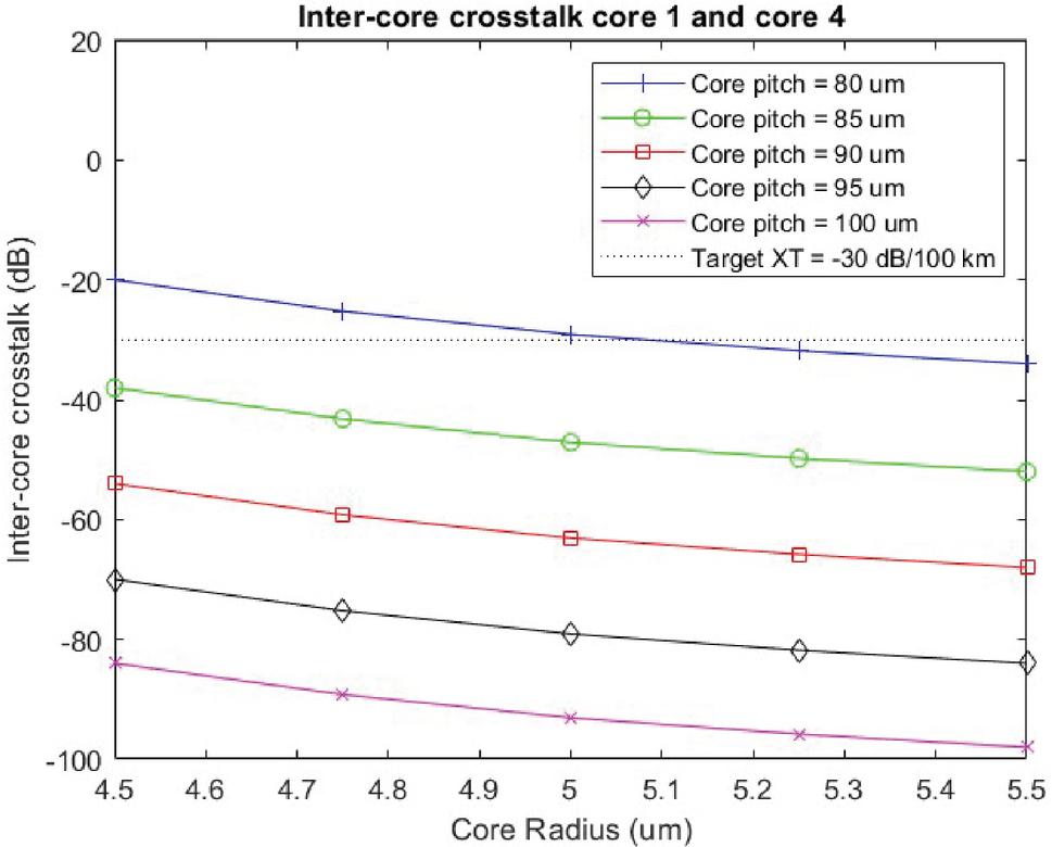
Figure 9 Inter-core crosstalk by different core radius (core#1 and core#4).
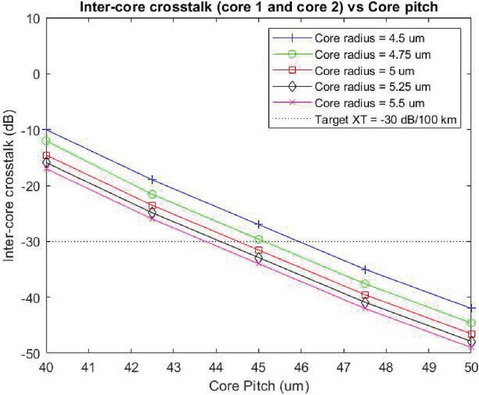
Figure 10 Inter-core crosstalk by different core pitch (core 1 and 2).
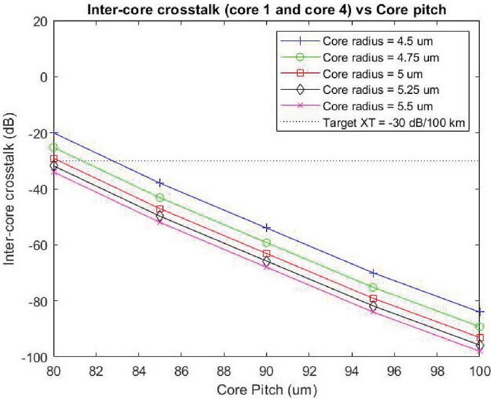
Figure 11 Inter-core crosstalk by different core pitch (core 1 and 4).
The cross-talk values for core#1 and core#4 according to Figure 4 by comparing them with the different core radius are simulated with the parameters detailed in Table 1.
From the simulation results, Figure 9 shows the XT variation between core#1 and core#4 when the core pitch has different. For the core pitch of core#1 and core#4 is 85 m, the crosstalk between core#1 and core#4 has under 30 dB/100 km. For larger core pitch 50 m, the XT has under 30 dB/100 km upon used core radius at 4.5 m. It is noticed that the core radius increases, the XT will be decreased.
Then, the cross-talk values for core#1 and core#2 followed in Figure 4 by comparing them with the different core pitch are simulated with the parameters detailed in Table 1.
From the experimental results, the effect of inter-core crosstalk with different core pitch is shown in Figure 10. The crosstalk between core#1 and core#2 is lower 30 dB/100 km with the core pitch at 46 mm. It is seen that the inter-core crosstalk at core radius between 4.5 to 5.5 m are over the 30 dB/100 km. Therefore, it is concluded that the XT will be increasing, when the core radius increases.
Finally, the inter-core cross-talk values for core#1 and core#4 according to Figure 4 in comparison with the core pitch are shown in Figure 11. The inter-core crosstalk between core#1 and core#4 is lower than 30 dB/100 km, when the core pitch is at 84 mm. From these experimental results, it is summarized that the core pitch between 47.5 m to 50 m and the core radius starts from 4.5 m to 5.5 m can apply for next-generation inter-data center networks with the crosstalk lower than 30 dB/100 km.
7 Conclusion
We have designed the homogeneous multi-core fibers using a four-core structure under the limitations of single-mode propagation and inter-cross talk between the neighboring cores. For the proposed inter-data center transmission system, the simulation results are shown that it is to support the high bandwidth without adding the high investment and other techniques. The relationships between XT and various fiber parameters as core radius and core pitch have been analysed to achieve the best MCF design with crosstalk lower than 30 dB/100 km. From the experimental results of inter-core crosstalk, the core pitch at 47.5 m to 50 m and the core radius starts from 4.5 m to 5.5 m can apply for future inter-data center networks. In further research, the idea of four-core coupled multicore fiber will be considered. That can improve the transmission system of intra-data center network.
References
[1] Cisco, ‘Cisco Global Cloud Index 2015-2020’, White Paper, pp. 1-41, 2016.
[2] K. Saitoh, S. Matsuo, “Multicore Fiber Technology”, In Proceeding of the Optical Fiber Communications Conference and Exhibition, pp. 22, 2015.
[3] T. Hayashi, “Multi-core Fiber for High-capacity Spatially-multiplexed Transmission”, Ph.D. Thesis, Hokkaido University, Sapporo, Japan, 2013.
[4] T. Hayashi, Y. Tamura, T. Hasegawa and T. Nakanishi, “Coupled Multi-Core Optical Fiber Suitable for Long-Haul Transmission”, SEI Technical Review, Number 85, Oct., 2017.
[5] T. Hayashi, T. Nakanishi, “Multi-core Optical Fibers for the Next-Generation Communications”, SEI Technical Review, Number 86, Apr., 2018.
[6] R.-J. Essiambre, G. Kramer, P.J. Winzer, G.J. Foschini, and B. Goebel, “Capacity Limits of Optical Fiber Networks”, Journal of Lightwave Technology, 28(4): 662–701, 2010.
[7] T. Morioka, “New Generation Optical Infrastructure Technologies EXAT Initiative Towards 2020 and beyond”, In Proceeding of the Opto-Electronics and Communications Conference, pp. 13–17, Jul., 2009.
[8] H. Kubota, and T. Morioka, “Few-mode Optical Fiber for Mode Division Multiplexing”, Optical Fiber Technology, 17: 490–494, 2011.
[9] T. Hayashi, “Uncoupled Multi-core Fiber Enhancing Signal-to-Noise Ratio”, Optics Express, 20(26): B94–B103, Nov., 2012.
[10] J. K. Perin, A. Shastri and J. M. Kahn, “Data Center Link Beyond 100 Gbit/s per Wavelength”’, Optical Fiber Technology, 44: 69–85, Aug., 2018.
[11] R. Urata, H. Liu, X. Zhou and A. Vahdat, “Datacenter Interconnect and Networking: From Evolution to Holistic Revolution”, In Proceeding of the Optical Fiber Communications Conference, W3G.1, 2017.
[12] T. Matsui, “Design of 125 um Cladding Multi-core Fiber with Full-band Compatibility to Conventional Single-mode Fiber”, In Proceeding of the European Conference on Optical Communication, 2015.
[13] T. Hayashi, “End-to-End Multi-core Fibre Transmission Link Enabled by Silicon Photonics Transceiver with Grating Coupler Array”, In Proceeding of the European Conference on Optical Communication, 2017.
[14] D. Kumar, R. Ranjan, “Estimation of Crosstalk in Homogeneous Multicore Fiber for High Core Count under Limited Cladding Diameter”, In Proceeding of the Conference on Information and Communication Technology, Nov., 2017.
[15] G. Rademacher, “Crosstalk Dynamic in Multi-core Fibers”, Optics Express, 25(10): 12020–12028, May., 2017.
[16] M. Koshiba, K. Saitoh and Y. Kokubun, “Heterogeneous Multi-core Fibers: Proposal and Design Principle”, IEICE Electronics Express, 6(2): 98–103, Jan., 2009.
[17] T. Hayashi, T. Nagashima, O. Shimakawa, T. Sasaki and E. Sasaoka, “Crosstalk Variation of Multi-core Fibre Due to Fibre Bend”, In Proceeding of the European Conference on Optical Communication, Torino, 2010.
[18] T. Hayashi, T. Taru, O. Shimakawa, T. Sasaki, and E. Sasaoka, “Design and Fabrication of Ultralow Crosstalk and Low-Loss Multi-core Fiber”, Optics Express, 19(17): 16576–16592, Aug., 2011.
[19] D. Kumar, R. Ranjan, “Crosstalk Analysis in Homogeneous 12-core Multicore Fiber with Different Core Layouts for LP01 and LP02 Modes”, In Proceeding of the IEEE Region 10 International Conference, pp. 2305–2408, 2017.
[20] K. Okamoto, “Fundamentals of Optical Waveguides”, 2nd edition, Academic Press, San Diego, USA, 2006.
Biographies

Jirasak Ponchua received the M.Sc. degree in Information Technology major Networking from Mahanakorn University of Technology, Bangkok, Thailand in 2007. Currently, he studies toward the D.Eng. degree in Electrical Engineering at Mahanakorn University of Technology, Bangkok, Thailand. His research interests include fiber optic and digital signal processing for telecommunications.

Suchada Sitjongsataporn received the B.Eng. (First-class honours) and D.Eng. degrees in Electronic Engineering from Mahanakorn University of Technology, Bangkok, Thailand in 2002 and 2009. She has worked as lecturer at department of Electronic Engineering, Mahanakorn University of Technology since 2002. Currently, she is an Associate Professor and the Associate Dean for Research at Faculty of Engineering and Technology in Mahanakorn University of Technology. Her research interests are the mathematical and statistical models in the area of adaptive signal processing for wireline and wireless communications, networking, embedded system, image and video processing.
Journal of Mobile Multimedia, Vol. 18_2, 163–178.
doi: 10.13052/jmm1550-4646.1821
© 2021 River Publishers