LCP Based Planar High Q Embedded Band Pass Filter for Wireless Applications
V. Satheesh Kumar1 and S. Ramesh2
1Department of ECE, T.J.S Engineering College, Chennai, India
2Department of ECE, Valliammai Engineering College, Chennai, India
E-mail: satheeshtjs@gmail.com; rameshs.ece@valliammai.co.in
Received 26 January 2018; Accepted 27 April 2018;
Publication 21 July 2018
Abstract
A novel miniaturized high-Q embedded passive polymer substrate based bandpass operating at L Band is offered. A low profile, compact filter with high performance and high rejection out of band is presented. High Q passives such as inductors, capacitors and matching networks are embedded in the filter. It is easy to design. Embedded layers are integrated for 3D integration, parasitics are removed and interconnection losses are bargained by de embedding method. The filter is designed, simulated for L band frequency for miniaturized mixed signal applications.
Keywords
- Embedded passives
- High-Q
- Polymer
- Band Pass Filter
1 Introduction
Wireless communication systems have been the most active part of modern electronics in the last few decades. The wireless revolution is touching on and reshaping many aspects of the daily life. Budding trends of dependence on wireless connectivity and increasing expectations of the information expressway are the strong indicators show that wireless technologies will continue to grow. To meet expectations and deliver the required bandwidth,
Filters in the front-end module play a significant role for controlling the frequency bands of wireless standards as well as block the unwanted frequency bands. Every wireless product has one or more filters in their RF circuit architecture as shown in Figure 1 [2]. Hence, not only the filter-integration technology, but also the design technique and the performance of filters become critically important for wireless
In mobile products, for example, 90% of the system components correspond to passives, which typically add up to some 400 discrete passive components and their metal interconnections on the substrate [3, 4].
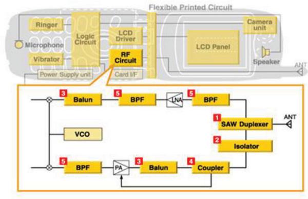
Figure 1 Block diagram of RF circuit in cell phone [2].
Trimness, portability, outlay and concert have been the driving force for the evolution of packaging and system-on-package (SoP) approach in RF, microwave and millimetre wave applications. Recent research shows SoP to be a more realistic and low cost key than system-on-chip (SoC)
SoC is a fully built-in design with RF passives and digital and/or optical functions on-wafer [6]. SoP condenses space eager analog components into a multilayer dielectric material and integrates chips within or on the same dielectric packaging material [7]. SoP modules resolve the major shortfalls of SoC by providing a low-loss substrate material for the RF passives and a exceptional space-saving capability for chip integration in or on the substrate [8].
Low temperature co-fired ceramic (LTCC) has striking electrical characteristics, dense multilayer circuit integration, and very excellent package hermeticity, but the cost is also relatively high [9]. However, due to the capability for LCP to do reel-to-reel processing, it is probable that production costs will continue to go down. In addition, multilayer circuits are possible due to two types of LCP material with different melting temperatures. Elevated melting temperature of LCP (315∘C) can be used as core layers, while low melting temperature LCP (290∘C) is used as a bond ply. Thus, vertically integrated designs may possibly be realized similar to those in LTCC. An additional benefit in multilayer LCP builds is the functionality provided by the low dielectric constant. The practice of LCP as a microwave circuit substrate is not a new idea. It has been around in thin-film form since the early 1990s when it was first documented as a candidate for microwave
Liquid crystal polymer (LCP) provides the all-in-one solution for integration move towards high quality dielectric, for high performance multiband passive design, an excellent substrate for heterogeneous SOP integration as well as for MEMS structures [13]. Embedded passive technology is a key enabling technology for high levels of system integration in SoP. This technology requires advanced fabrication techniques and substrate materials to satisfy very demanding performance requirements.
2 Polymer Technology
LTCC technology has lower loss at high frequencies and lower coefficient of thermal expansion (CTE) than FR4. However, LTCC cannot be integrated into the inner circuit layers of printed circuit boards (PCBs) and has to be used as discrete component. This causes high cost of integration and reliability issues [14]. Both LCP and Polymer are flexible with thin and low dielectric constant, But LCP having the low Loss tangent compared to polymer.
LCPs make up a family of thermoplastics which have a unique set of properties. They perform very well in harsh environments, including high heat resistance and tolerance, high electrical resistance, and high chemical resistance. Unlike other polymers such as ABS or nylon, LCPs show a high degree of anisotropy in both solid and liquid crystal phases. This means that the strength, stiffness, and thermal expansion will be greater in one direction, not the same in every direction.
Low loss organic materials like Liquid Crystalline Polymer (LCP) allow the realization of high-Q passives embedded in the packaging substrate, allowing the designer to realize completely integrated wireless systems [15]. Because of its low loss and minimal dependency on temperature, LCP has been proven as an exceptional candidate for RF applications [16].
Single layer LCP for front end has been characterized and used for diverse applications such as LNAs, filters, baluns, and VCOs. As shown in Figure 1, a mixture of standards needs to be integrated as modules to accommodate increasing demands not only for voice communication, but also for other multimedia applications and GPS. In this regards, 3D integration is significant. Therefore, the vertical integration by 3D design with multilayer substrate is essential. The height of the system module is also restricted for squashed size of portable devices. Moreover, the overall integration cost is also a key consideration. All these requirements can be met with 3D LCP based integration [17–20].
LCP based technology are existing in single [13–16], three, and balanced configuration. Three LCP layers are bonded together by a lower melt adhesive (CORE). This method combines 25um thick LCP dielectric with low loss tangent glass-reinforced organic prepregs in a multilayer stack-up. Based on this process, 4–10 metal layer laminates have been fabricated. The LCP layer has a dielectric constant of 2.9 and a loss tangent of 0.002 [20]. The adhesive layers have a loss tangent of 0.0035 with a dielectric constant of 3.38. The top metal layer of the cross-section can be used for surface mount components and for the incorporation of high Q (>100) inductors. The bottom metal can be used for microstrip ground layer. The facility to form micro-vias in the stack up provides increased component density as well as increased routing density.
In this paper, LCP and Dupond Polymer performance are compared by designing and simulating the High Q Band Pass Filter.
3 Bandpass Filter Topology
To exhibit the performance of the planned circuit schematic in LCP material, BPFs are designed using the circuit schematics shown in Figure 3 [21]. First, each lumped-element values are calculated by the classical microwave design equations. After obtaining all of the lumped-element values, each element is replaced by the corresponding layout. With the multilayer capability of the LCP substrate, the lumped-elements can be readily realized by using a Spiral metal strip for the inductor and parallel-plates for the capacitor. Figure 2 shows the conventional second-order capacitively-coupled topology. Unless the size of filter is increased, the predictable topology cannot satisfy the demanding high-rejection specifications because the slope of the stopband is directly related to the order of filter (number of LC resonator tank circuits).
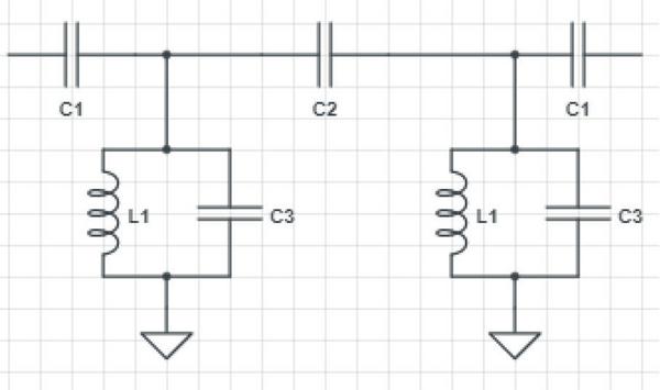
Figure 2 Conventional capacitively-coupled topology.
Table 1 Lumped element values
| L1 | C1 | C2 | C3 |
| 9 nH | 0.3 pF | 0.2379 pF | 0.3 pF |
Design equations for calculating the component values of the capacitively coupled filters can be derived by using standard filter synthesis procedures [22]. Before calculating the component values, the fractional bandwidth of the passband and admittance inverter can be defined as
Where f1 and f2 denote the edges of the passband, f0 is the center frequency, gn is either Butterworth or Chebyshev constants, and Z0 is the characteristic impedance.
The synthesis begins with selection of the inductor L1. The inductance value L1 is generally chosen to have a maximum realizable quality factor depending on the substrate and fabrication technology. For LCP technology, it has been shown that inductor quality factor has a range of 70∼100 from 2 to 5 GHz [22]. Then, the capacitance values are computed using
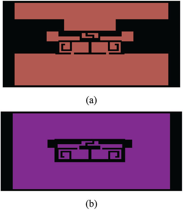
Figure 3 Fabrication Layout of the designed Band pass Filter.
The filter was simulated in SONNET. The two-layer balanced LCP process technology is used for the design of the components. The configuration of the LCP and prepreg allows a thin cross-section height, passives to be distributed over different LCP layers to minimize undesired coupling, large inductors can be made over the two closely spaced LCP layers, and design in a strip line environment leading to minimization of losses resulting from radiation. These features make the technology especially suitable for filter design. Compared with conventional filter, narrow band, compact size of filter and good rejection is achieved.
Table 2 Material properties
| Material | Dielectric Constant | Loss Tangent | Thickness in mm |
| Polymer | 3.4 | 0.010 | 0.05 |
| LCP | 2.95 | 0.002 | 0.05 |
4 Results Discussion
The frequency response of the proposed Band Pass Filter is shown in Figure 3. As seen in this figure, the objective is to design a bandpass filter with the central frequencies as those of L Band. The same design was simulated for two different materials. Due to slight change in the dielectric constant, for the same design we are getting two diifferent resonant frequencies. Dielectric constant in plastics is directly related to the polarizability of the polymer. Central frequency of the band is fixed on 1.5 GHz, has insertion losses of 1 dB, return losses of -21 dB and bandwidths of 6 MHz is achieved using Polymer as a substrate. While for the same design in LCP, the central of 1.6 GHz, with insertion losses of 1 dB, return losses of -20 dB and bandwidths of 7 MHz is achieved.
Table 3 Performance comparison
| Material | Insertion Loss | Bandwidth | Return Loss |
| Polymer | 1 dB 1.44 to 1.5 GHz | 6 MHz | –21 dB |
| LCP | 1 dB 1.54 to 1.61 GHz | 7 MHz | –20 dB |
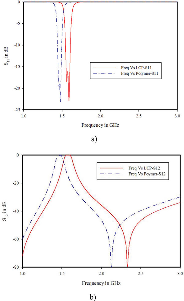
Figure 4 Comparison between Polymer and LCP a) S11 b) S12.
5 Conclusion
In this paper, initially the design of Band Pass Filter for L-band frequency of operation is designed using the classical microwave design equations. After calculating lumped-element component values each element is replaced by the corresponding layout on thin LCP substrate and polymer. The filters exhibited low insertion losses as 1 dB 1.44 to 1.55 GHz in polymer and 1 dB 1.54 to 1.61 GHz in LCP. The high Qs of the passive components on LCP permit low insertion losses with good out-of-band rejection with bandwidth of 6 MHz bandwidth in Polymer and 7 MHz in LCP without prohibitively increasing the size of the components. Thus, by using polymer based filters the narrow band, compact size, low insertion loss and high out of band rejection is achieved. The most common L-band applications for these types of filters include their use in International Marine/Maritime Satellite (INMARSAT) and other satellites, radio astronomy, defense, meteorological satellite services, radar, C-band down conversion, global navigation satellites systems such as GPS, telemetry, digital audio broadcasting and amateur radio.
Acknowledgements
The authors wish to acknowledge the assistance and support by Mr. M.Vinod from NTU, Singapore, in manufacturing support.
References
[1] El-Ghazaly, S. M. et al. (2001). Recent trends and enabling technologies in RF and microwave applications. In IEEE Microwave Conference, 2001. APMC 2001. 2001 Asia-Pacific (Vol. 3, pp. 978–983).
[2] EVDO/EVDV. “http://ecee.colorado.edu/∼ecen4242/evdo/evdowebpa
[3] Tummala, R. R. (2006). Moore’s law meets its match (system-on-package). IEEE Spectrum, 43(6), 44–49.
[4] Xinhai, B., Hongyan, G., Li, Z., Tan, K. H., and Lai, C. M. (2014). Fabrication and measurement of BPF using IPD technology. In IEEE Electronic Packaging Technology (ICEPT), 2014 15th International Conference on (pp. 36–38).
[5] Pinel, S., Davis, M., Sundaram, V., Lim, K., Laskar, J., White, G., and Tummala, R. (2003). High Q passives on Liquid Crystal Polymer substrates and BGA technology for 3D integrated RF Front-End Module. IEICE Transactions on Electronics, 86(8), 1584–1592.
[6] Matsuzawa, A. (2002). RF-SoC-expectations and required conditions. IEEE Transactions on Microwave Theory and Techniques, 50(1), 245–253.
[7] K. Lim, et al., (2002). “RF-SOP for wireless communications,” IEEE Microwave Mag., vol. 3, pp. 88–99.
[8] Thompson, D. C., Tantot, O., Jallageas, H., Ponchak, G. E., Tentzeris, M. M., and Papapolymerou, J. (2004). Characterization of liquid crystal polymer (LCP) material and transmission lines on LCP substrates from 30 to 110 GHz.IEEE Transactions on Microwave Theory and Techniques, 52(4), 1343–1352.
[9] Kutilainen, T., (2003). Ceramic interconnect initiative. nextGen 2003, LTCC. [Online]. Available: http://www.imaps.org/ cii/NextGen2003.pdf
[10] Jayaraj, K., Noll, T. E., and Singh, D. R. (1995). “RF characterization of a low cost multichip packaging technology for monolithic microwave and millimeter wave integrated circuits,” in URSI Int. Signals, Systems, and Electronics Symp., 443–446.
[11] Culbertson, E. C. (1995). A new laminate material for high performance PCBs: Liquid crystal polymer copper clad films. In IEEE Electronic Components and Technology Conference, 1995. Proceedings., 45th (pp. 520–523).
[12] Jayaraj, K., Noll, T. E., and Singh, D. R. (1995). A low cost multichip packaging technology for monolithic microwave integrated circuits. IEEE transactions on antennas and propagation, 43(9), 992–997.
[13] Sarkar, S., Wang, G., Tentzeris, M., et al., (2004). “RF and mm-wave SOP module platform using LCP and RF MEMS technologies” Conference Paper in IEEE MTT-S International Microwave Symposium digest.
[14] Dalmia, S., Sundaram, V., White, G., & Swaminathan, M. (2004). Liquid crystalline polymer (LCP) based lumped-element bandpass filters for multiple wireless applications. In IEEE Microwave Symposium Digest, 2004 IEEE MTT-S International(Vol. 3, pp. 1991–1994).
[15] Dalmia, S., Sundaram, V., White, G., and Swaminathan, M. (2004). Liquid crystalline polymer based RF/wireless components for multi-band applications. In IEEE Electronic Components and Technology Conference, 2004. Proceedings. 54th (Vol. 2, pp. 1866–1873).
[16] Govind, V., Dalmia, S., Sundaram, V., White, G. E., and Swaminathan, M. (2004). Design of multiband baluns on liquid crystalline polymer (LCP) based substrates. In IEEE Electronic Components and Technology Conference, 2004. Proceedings. 54th (Vol. 2, pp. 1812–1818).
[17] Qiu, Y., Xia, L., and Yang, L. (2015). A compact bandpass filter using multilayer LCP technology. In Communication Problem-Solving (ICCP), 2015 IEEE International Conference on (pp. 243–245).
[18] Lan, Y., Xu, Y., Mei, T., Wu, Y., and Xu, R. (2016). A 2∼ 18GHz compact microwave band-pass filter suitable for planar and three-dimension flexible integration. In Microwave Conference (EuMC), 2016 46th European (pp. 528–531).
[19] Keramat, M. (1997). Yield Optimization of Electronic Circuits via Improved CG Algorithm. In IEEE 40th Midwest Symp CAS.
[20] Yun, W., Sundaram, V., and Swaminathan, M. (2007). High-Q embedded passives on large panel multilayer liquid crystalline polymer-based substrate. IEEE transactions on advanced packaging, 30(3), 580–591.
[21] Bavisi, A., Swaminathan, M., and Mina, E. (2007). Liquid crystal polymer-based planar lumped component dual-band filters for dual-band WLAN systems. In IEEE Radio and Wireless Symposium, (pp. 539–542).
[22] Hwang, S. E. (2011). Characterization and design of embedded passive circuits for applications up to millimeter-wave frequency (Doctoral dissertation, Georgia Institute of Technology).
Biographies
V. Satheesh Kumar received his B.E in Electronics and Communication Engineering from Madurai Kamaraj University Madurai, Tamilnadu M.E in VLSI Design from Anna University, Chennai, Tamilnadu. He is currently, working as an Associate Professor in the department of Electronics and Communication Engineering, T.J.S Engineering College, Chennai with experience of 15 years. Life member in IETE, ISTE, authored papers in reputed journals and international/national conferences. His area of interest includes Antennas & Propagation and Wireless Communications.

S. Ramesh received his B.E in Electronics and Communication
Journal of Mobile Multimedia, Vol. 14_3, 307–318.
doi: 10.13052/jmm1550-4646.1433
© 2018 River Publishers