Design of Dual-Band and Low-Profile SIW Cavity-Backed Slot Antenna for 5G Applications
Amit Kumar* and Amit Kumar Singh
Department of Electronics Engineering, Indian Institute of Technology (BHU), Varanasi, India
E-mail: amitk.rs.ece17@iitbhu.ac.in; aksingh.ece@iitbhu.ac.in
*Corresponding Author
Received 29 September 2020; Accepted 30 November 2020; Publication 26 January 2021
Abstract
In this communication, the design of a dual-band and low-profile SIW cavity-backed slot antenna operating at K-band and Ka-band has been proposed to expand the Impedance bandwidth (IBW) of the antenna. The dual-band antenna consists of the SIW cavity with two parallel slots etched on the conductor’s ground plane. To obtain a dual-band, higher-order hybrid modes are tuned and combined to form the second band of the proposed antenna with a broader bandwidth. For dual-band antenna, fractional bandwidth of 5.26% and 6.15% are attained with the maximum gain of 5.45 dBi and 6.15 dBi at 24.7 GHz and 27.8 GHz, respectively. A cavity-backed antenna using via-hole and the slot has been proposed to improve an IBW and other antenna performance parameters. Via-hole establishes a connection between the top and bottom surfaces of the cavity, creating a new path for the current to flow by shortening the slot’s effective length. An IBW of 4.2 GHz (15.32%), where a gain of 7.8 dBi and 9.2 dBi have been realized at 25.9 GHz and 28.8 GHz, respectively. Isolation of less than 25 dB has been achieved through simulation. In terms of , the overall volumetric dimension of the proposed antenna is 1.68 . The proposed design demonstrates better performance in terms of antenna parameters, including compactness, good radiation characteristics, enhanced impedance bandwidth, and higher gain than the latest state of the art.
Keywords: Cavity-backed, dual-band, substrate integrated waveguide (SIW), slot antenna, 5G.
1 Introduction
Inspired by the rapid advancement of the portable web and the Internet of things (IoT), the fifth-generation wireless communication system (5G) has garnered significant interest within the business and academic communities. There is an intellectual research activity around the world in developing the next generation of 5G wireless networks. There has been a lot of enthusiasm within the antenna community for developing an effective antenna for future 5G design. The experiments’ results have demonstrated that the groups of 28 GHz band and 38 GHz band are taken into account for the 5G millimeter-wave framework [1]. At present, there is a requirement for low cost and low profile antennas that can be gradually embedded into objects.
In recent years, slot antennas have been utilized broadly as one of the popular options for achieving low profile, compatible antennas in radar, T.V, and marine systems applications [2–4]. Many studies have been performed on multi-frequency slot antennas in the literature [5, 6]. One of the significant drawbacks of these designs is the backward radiation pattern that limits its performance in many applications. Nowadays, substrate integrated waveguide (SIW) technology has emerged as a promising candidate that implements non-planar waveguides structures in a planar way by utilizing the rows of metal vias to produce lateral metal sidewalls in the planar substrate. So, these types of antennas have the advantages of both metallic cavity-backed antennas and planar antenna technology. They offer the advantage of eliminating the backward radiation compared to the conventional patch antennas and higher gain and radiation efficiency levels [2–4]. Various strategies have been suggested to stun the narrow IBW of the cavity-backed slot antenna [7–9] utilizes dual resonance to obtain broadband characteristics. Two slots are used in [7–9] to construct a dual resonance. These antennas have a uniform gain over the operating frequency. This technique gives the antenna dual-band or wide-band characteristics based on the size of the slots. However, the size of the cavity is increased by using these techniques by optimizing the slots’ positions on the surface of the cavity.
In [10], a higher IBW (2.16%) is accomplished by eliminating the substrate present under the resonating slot for improving the IBW. It makes the overall design irregular and expensive. A ramp-shaped slot is used in [11], which is working in 1st negative-order resonance. However, the miniaturization is limited to the geometrical dimensions and presented area on the antenna’s top conducting surface. The other techniques to enhance the IBW are to merge multiple resonant modes [12, 13]. In [12], the non-resonant slot is used to excite the hybrid modes of the cavity. By tuning the two-hybrid modes adjacent to each other, IBW rises up to 6.3%. To achieve broader IBW, a bow-tie slot was introduced in cavity-backed antenna in [13]. The IBW of the antenna was increased to 9.4%, while a comparatively lower gain of 3–4 dBi has been obtained. Slotted patches [14], half-mode type SIW cavity-backed antenna [15], subsequently, these techniques enhanced the operating IBW such as 10.9% in [14], 10% in [15] but enlarged the antenna size by 27% and made the radiation pattern non-uniform due to half-open structure. Furthermore, a multi-layered SIW cavity-backed antenna [16] provides a 10.9% IBW, but the antenna structure needs an exact configuration of different substrates due to its multilayer structure. Gap coupling has also been used to expand the IBW with parasitic patches up to 12% [17].
To overcome the limitations mentioned above in terms of IBW, gain, and compactness simultaneously, we have proposed designing a dual-band and low-profile SIW cavity-backed slot antenna for (5G) wireless system. Two parallel slots are utilized to obtain dual-band of the SIW cavity-backed antenna. A cavity-backed antenna using a via-hole and the slot has been designed to achieve wider bandwidth and high gain. The proposed antenna has a via-hole along with the slot to create a dual resonance.
2 Antenna Design
2.1 Dual-Band SIW Cavity-Backed Antenna with Parallel Slots
The proposed antenna has been fabricated on substrate dimensions of mm at 28 GHz on Rogers RT/Duroid 5880 substrate of thickness 0.508 mm, the permittivity of 2.2, and loss tangent of 0.0009. The proposed antenna layout and geometrical parameters are outlined in Figure 1. Table 1 displays the geometrical parameters of the planned structure. The slotted cavity walls and feeding SIW are satisfied with these two conditions and [17]. The radiating antenna (or cavity) dimensions can be calculated, as discussed in [18].
| (1) | ||
| (2) |
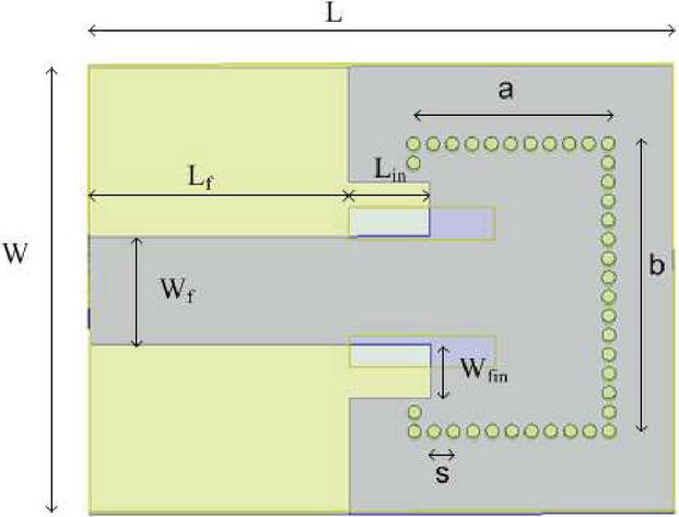
Figure 1 The geometrical configuration of the dual-band SIW cavity-backed antenna with parallel slots.
Table 1 Geometrical parameters of the proposed antenna
| Parameter | Value (mm) | Parameter | Value (mm) |
| L | 18 | a | 6 |
| W | 14 | b | 9 |
| W | 3.37 | S | 4.5 |
| L | 8 | S | 1 |
| L | 2.5 | d | 0.4 |
| W | 1.68 | s | 0.6 |
| d1 | 3 |
Where and represents the length and width of the cavity, respectively (in mm), stands for the relative permittivity of the substrate, and , Both are the resonance frequencies (both are in GHz). The must be greater than 0.05 to have mechanical stability. Two parallel slots are etched on the ground plane of the conductor. To obtain dual-band, an additional slot is introduced at the bottom plane of the cavity. It is observed that the Q factors of the two original modes are considerably reduced, and also a new mode is excited in the SIW cavity. The slot’s strong capacitive load effect switches the cavity mode to a lower frequency range, and at 24.7 GHz, the first antenna band is obtained. By optimizing the slots’ positions, length and width, higher-order hybrid modes are optimized and merge to form the second band is generated at 27.8 GHz of the proposed antenna with a broader bandwidth.
All simulations are performed using ANSYS version 18.0 based on the finite element method (FEM) technique. The corresponding reflection coefficient is existing in Figure 2. All material losses are taken into account when simulating the results. The simulated resonant frequencies are obtained at 24.7 GHz and 27.8 GHz. The simulated 10 dB operating bands are obtained in the range from 24.1 GHz to 25.4 GHz and from 26.8 GHz to 28.5 GHz with a fractional bandwidth of 5.26% and 6.15%, respectively. The radiation diagrams of E-plane and H-plane within the working frequency band are illustrated in Figures 3 and 4, respectively. The isolation level in E-plane, and H-plane is less than 35 dB at 24.7 GHz and 27.8 GHz. The achieved simulated gain value is about 5.45 dBi and 6.15 dBi at 24.7 GHz and 27.8 GHz. To enhance the bandwidth and achieve high gain, SIW based cavity-backed antenna via-hole, and the slot are designed.
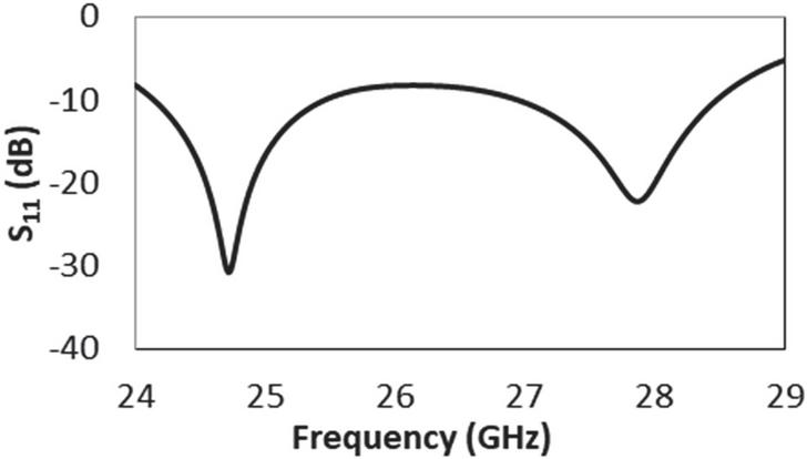
Figure 2 Simulated reflection coefficient (S) of the dual-band SIW cavity-backed antenna with parallel slots.
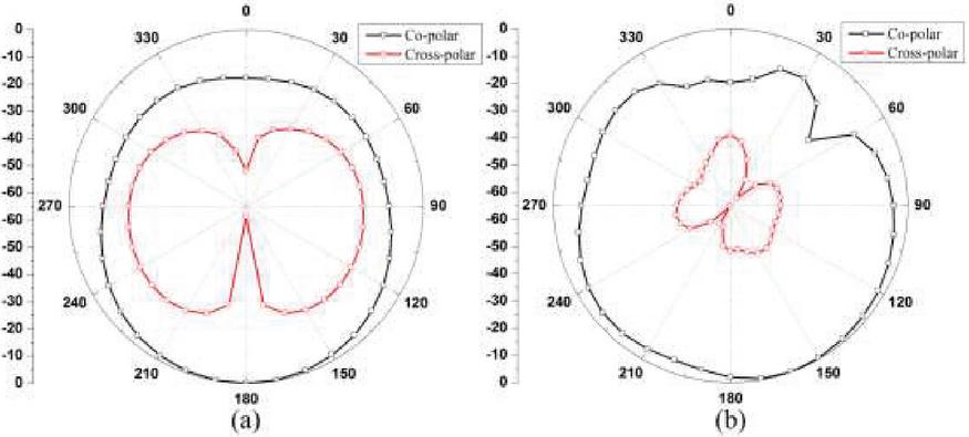
Figure 3 The simulated radiation patterns of the proposed antenna at 24.7 GHz. (a) E-plane. (b) H-plane.
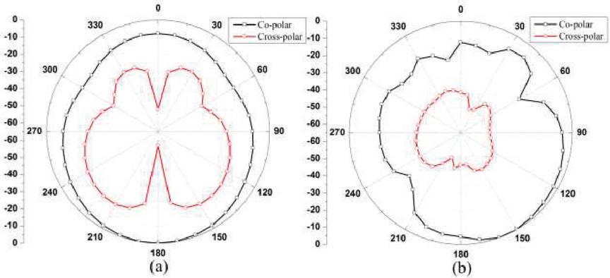
Figure 4 The Simulated radiation patterns of the proposed antenna at 27.8 GHz. (a) E-plane. (b) H-plane.
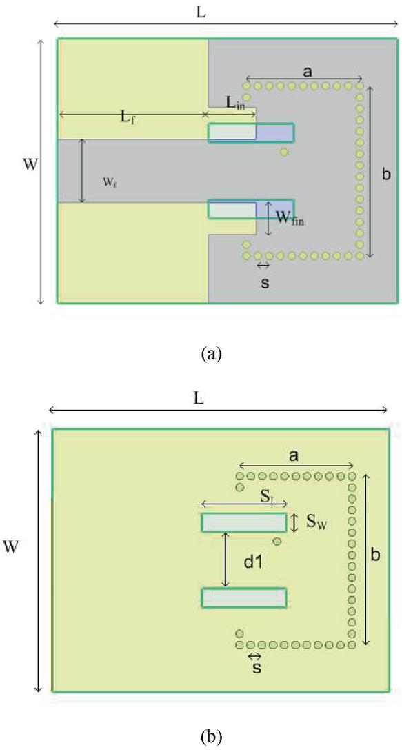
Figure 5 The geometrical configuration of the cavity-backed antenna using via-hole along with the slot. (a) Top view. (b) Bottom view.
2.2 Cavity-Backed Antenna Using Via-Hole Along with the Slot
To enhance the IBW, a cavity-backed antenna using via-hole along with the slot has been proposed. All the specification parameters are the same as those addressed for dual-band SIW cavity-backed antenna with a parallel slot. Figure 5 shows the possible antenna design. When the slot has half a wavelength at the operating frequency, the phenomenon of resonance is found in a typical cavity-backed slot antenna. Two fundamental factors defining the frequency of this resonance are the cavity size and slot length. The current distribution during the first resonance comprises minimum current flowing to the center and maximum current flows to the slot’s edges in the same direction. Via-hole establishes a connection between the top and bottom surface of the cavity creating a new path for the current to flow. At the time of second resonance, minimum current flows to the opposite side of the via-hole and maximum current flow to the slot’s left edge. The sufficient length of the slot is shortened at a higher resonance frequency. By moving the position of the via-hole, the second resonance frequency can be shifted to a higher or lower frequency without any significant effect on the first resonance frequency.

Figure 6 Simulated reflection coefficient (S) of the cavity-backed antenna using via-hole along with the slot.
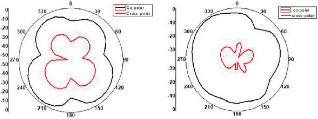
Figure 7 The simulated radiation patterns of the proposed antenna at 25.9 GHz. (a) E-plane. (b) H-plane.
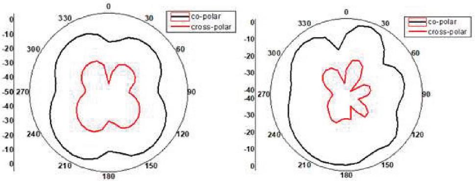
Figure 8 The simulated radiation patterns of the proposed antenna at 28.8 GHz. (a) E-plane. (b) H-plane.
To formalize the antenna design, the return loss i.e. (S11) of the antenna was acquired from the simulation as shown in Figure 6. The frequency spectrum used for the simulation is 24 to 29 GHz with a 10 dB return loss bandwidth of 4.2 GHz. From the figure, two resonances can be combined to ensure wide-band matching. The fractional bandwidth obtained for S dB is 15.32% (25.3 GHz–29.5 GHz). This outcome gives higher IBW much higher than the normal SIW slot antenna.
The simulated radiation patterns in E-plane and H-plane are illustrated in Figures 7 and 8, respectively. The isolation level in E-plane, and H-plane is less than 28 dB and 35.4 dB, respectively, at 25.9 GHz. The isolation level in E- and H-plane is less than 25 dB and 38 dB, respectively, at 28.8 GHz. The achieved simulated gain value is about 7.8 dBi and 9.2 dBi at 25.9 GHz and 28.8 GHz. This high gain and enhanced bandwidth were acquired because of via-hole and the slot in the proposed structure.
Table 2 Qualitative comparisons of reported antennas with respect to proposed antenna
| This work | |||||||
| Antenna | Antenna | ||||||
| Reference | I | II | [19] | [20] | [21] | [22] | [23] |
| Frequency (GHz) | 28 | 28 | 28 | 10 | 28 | 12 | 28 |
| Size (mm) | |||||||
| Slot’s characteristic | Two, parallel | Two, With via | One | Two, unilateral | Two, unilateral | One, cross | Two, ring |
| No. of resonance | Two | Two | Two | Three | one | Two | Two |
| FBW (%) | 5.2, 6.1 | 15.3 | 3.1 | 10.8 | 10.6 | 4.1 | 17.24 |
| Gain (dBi) | 5.8, 6.1 | 7.8, 9.2 | 6.5 | 4.4 | 8.4 | 5.8 | 7.8 |
A comparison between the proposed SIW antenna results with similar antennas reported in the literature is summarized in Table 2. The proposed SIW antenna shows a better IBW when compared with [19–22]. Reference [23] offers a larger impedance bandwidth as compared to the proposed antenna but less gain. The proposed antenna shows gain comparable to [19–23] and more compact.
3 Conclusion
A method to improve an IBW of the SIW cavity-backed antenna has been planned. For a dual-resonance antenna, a wide bandwidth is achieved by shortening the effective length of the slot at the higher frequency using a single via-hole along with the slot. It has been shown that the antenna using via-hole, along with the slot can achieve high gain and broader bandwidth performance when compared to dual-band antenna with parallel slots. The results show that the designed SIW antenna proves it an excellent candidate to cover the 5G wireless systems for countries like Europe, China, Japan, the USA, and Korea. Besides, it has the simplicity of a single monolayer structure and multiple resonance characteristics over a wide IBW.
References
[1] T. S. Rappaport et. al, ‘Millimeter-wave mobile communications for 5G cellular: It will work!’, IEEE Access, vol. 1, pp. 335–349, May, 2013.
[2] A. Kumar, and S. Raghavan, ‘Design of a broadband planar cavity-backed circular patch antenna’, AEU-International Journal of Electronics and Communications, vol. 82, pp. 413-419, Dec., 2017.
[3] C. Locker, T. Vaupel, and T. F. Eibert, ‘Radiation efficient unidirectional low profile slot antenna elements for X-band application’, IEEE Trans. Antennas Propag., vol. 53, pp. 2765–2768, 2005.
[4] T. Itoh, Y. Qian, and T. Yang, ‘Low-profile cavity-backed slot antenna using a uniplanar compact photonic band-gap substrate, U.S. Patent, 6:518–930, 2003.
[5] A. Kumar, and S. Raghavan, ‘Broadband SIW cavity-backed triangular-ring-slotted antenna for Ku-band applications’, AEU-International Journal of Electronics and Communications, vol. 87, pp. 60–64, 2018.
[6] A. Kumar, M. Saravanakumar, S. Raghavan, ‘Dual-frequency SIW-based cavity-backed antenna’, AEU-International Journal of Electronics and Communications, vol. 97, pp. 195–201, 2018 Dec.
[7] D. Sievenpiper, H. P. Hsu, and R. M. Riley, ‘Low-profile cavity-backed crossed-slot antenna with a single-probe feed designed for 2.34-GHz satellite radio applications,’ IEEE Trans. Antennas Propag., vol. 52, no. 3, pp. 873–879, 2004.
[8] Y. Liu, Z. Shen, and C. L. Law, ‘A compact dual-band cavity-backed slot antenna’, IEEE Antennas Wireless Propag. Lett., vol. 5, pp. 4–6, 2006.
[9] W. Hong and K. Sarabandi, ‘Platform embedded slot antenna backed by shielded parallel plate resonator’, IEEE Trans. Antennas Propag., vol. 58, no. 9, pp. 2850–2857, 2010.
[10] S. Yun, D.Y. Kim, and S. Nam, ‘Bandwidth and efficiency enhancement of cavity-backed slot antenna using a substrate removal’, IEEE Antennas Wireless Propag. Lett., pp. 1458–1461, 2012.
[11] A. P. Saghati, and K. Entesari, ‘An ultra-miniature SIW cavity-backed slot antenna’, IEEE Antennas Wireless Propag. Lett., vol. 16, pp. 313–316, 2017.
[12] G. Q. Luo, Z. F. Hu, W. J. Li, X. H. Zhang, L. L. Sun, and J. F. Zheng, ‘Bandwidth-enhanced low-profile cavity-backed slot antenna by using hybrid SIW cavity modes’, IEEE Trans. Antennas Propag., vol. 60, pp. 1698–1704, 2012.
[13] A. Kumar, S. Raghavan, ‘Bandwidth Enhancement of Substrate Integrated Waveguide Cavity-backed Bow-tie-complementary-ring-slot Antenna using a Shorted-via’, Defence Science Journal, vol. 68, pp. 197–202, 2018.
[14] W. Yang, and J. Zhou J, ‘Wideband low-profile substrate integrated waveguide cavity-backed E-shaped patch antenna’, IEEE Antennas Wireless Propag. Lett., vol. 12, pp. 143–146, 2013.
[15] H. Dashti, M. H. Neshati, ‘Development of low-profile patch and semi-circular SIW cavity hybrid antennas’, IEEE Trans Antennas Propag., vol. 62, pp. 4481–4488, 2014.
[16] A. Kandwal and S. K. Khah, ‘A novel design of gap-coupled sectoral patch antenna’, IEEE Antennas Wireless Propag. Lett., vol. 12, pp. 674–677, 2013.
[17] F. Xu, and K. Wu, ‘Guided-wave and leakage characteristics of substrate integrated waveguide’, IEEE Trans. Microw. Theory Tech., vol. 56, pp. 66–73, 2005.
[18] A. Kumar, S. Bhaskar and A. K. Singh, ‘SIW Cavity-Backed U-Shaped Slot Antenna for 5G Applications’, 2019 IEEE Asia-Pacific Microwave Conference (APMC), Singapore, Singapore, pp. 1485–1487, 2019.
[19] S. H. Quang, S. X. Ta, P. H. Bao, K. N. Khac, and C. Ngoc, ‘Compact circularly polarized slotted SIW cavity antenna for 5G application’, 2017 International Conference on Advanced Technologies for Communications (ATC), Quy Nhon, pp. 75–79, 2017.
[20] J. Q. Huang, D. Lei, C. Jiang, Z. Tang, F. Qiu, M. Yao, and Q. X. Chu, ‘Novel circularly polarized SIW cavity-backed antenna with wide CP beamwidth by using dual orthogonal slot split rings’, Progress In Electromagnetics Research C, vol. 73, pp. 97–104, 2017.
[21] J. Tan, W. Jiang, S. Gong, T. Cheng, J. Ren and K. Zhang, ‘Design of a dual-beam cavity-backed patch antenna for future fifth generation wireless networks’, in IET Microwaves, Antennas & Propagation, vol. 12, no. 10, pp. 1700–1703, 2018.
[22] S. Priya, K. Kumar, S. Dwari and M. K. Mandal, ‘Circularly Polarized Self-Diplexing SIW Cavity Backed Slot Antennas’, in IEEE Transactions on Antennas and Propagation, vol. 68, no. 3, pp. 2387–2392, 2020.
[23] A. Kumar, S. Bhaskar, A. K. Singh, A. Khan and A. K. Singh, ‘A Wideband Dual-Resonance SIW Cavity-Backed Slot Antenna for 5G Applications’, 2020 URSI Regional Conference on Radio Science (URSI-RCRS), Varanasi, India, pp. 1–4, 2020.
Biographies

Amit Kumar was born in Agra, Uttar Pradesh, India, in 1993. He received his B.TECH degree in Electronics and Communication Engineering from Ambedkar Institute of Advanced Communication Technologies and Research, Guru Gobind Singh Indraprastha University (GGSIPU), India, in 2014 and master’s degree in Electronics and Communication (ECE) from University School of Information, Communication and Technology (USIC&T), Guru Gobind Singh Indraprastha University (GGSIPU), India, in 2016. He is currently pursuing his PhD from Indian Institute of Technology (Banaras Hindu University), Varanasi, India. His research interests include SIW-based antennas and circuits, Broadband Antennas, Circularly Polarized antennas for MMW and THz Bands.

Amit Kumar Singh received the B.Tech. degree in Electronics engineering from VBS Purvanchal University Jaunpur (U.P), India in 2001, the M.E. degree in Communication Systems from Government Engineering College, Jabalpur (M.P), India in 2003, and the Ph.D. degree from the I.I.T. (B.H.U.) Varanasi in 2010 respectively. From May 2005 to September 2006, he was a Junior research fellow and Senior research fellow at the Faculty of Engineering and Technology, Banaras Hindu University, Varanasi, India. From September 2006 to October 2007, he was a Lecturer in the Department of Electronics & communication Engineering, B.I.T SINDRI, Dhanbad, India. He joined the Department of Electronics Engineering, Institute of Technology, Banaras Hindu University, as an Assistant Professor in October 2007. He was working as Assistant Professor in the Electronics Engineering department in IIT (BHU) since June 2012 to July 2018. He was working as Associate Professor in the Electronics Engineering department in IIT (BHU) since July 2012 to till date. His research interest includes the areas of design of millimeter frequency antennas, feeds for parabolic reflectors, dielectric resonator antennas, microstrip antennas, EBG, artificial magnetic conductors, soft and hard surfaces, Antennas for RFIDs, phased array antennas, and computer aided design for antennas. He has published over 70 journal articles and conference articles.
Journal of Mobile Multimedia, Vol. 17_1-3, 127–140.
doi: 10.13052/jmm1550-4646.17136
© 2020 River Publishers