Selecting IoT Connectivity Protocols for Rural Development Applications
Vinod Kumar
Director (Retd) in Wireless Research, Alcatel Lucent Bell Labs, France
E-mail: ramukdoniv@outlook.com
Received 21 September 2020; Accepted 30 November 2020; Publication 30 January 2021
Abstract
Data sensing and collection over vast coverage areas form an integral part of IoT applications such as Smart Farming. Selection of adequate IoT connectivity technologies is an important step in the design process. Overall energy efficiency, availability of low-cost and long-life sensor nodes and achievability of long coverage range of the fixed infrastructure are the main criteria of selection. After a brief description of the scenario of connectivity technologies, this article demonstrates the usefulness of a Low Power Wide Area Networking technology named SigFox for the applications mentioned above. Performance figures in terms of coverage range and protocol throughput (manageable IoT node density) justify this claim.
Keywords: IoT for Smart Farming, connectivity protocols, energy efficiency, SigFox, 2-D Aloha protocol, RFTDMA.
1 Introduction
Smart Agriculture and Smart Farming including livestock tracking and management are two major applications of IoT technologies in rural development. Selection of an adequate telecom protocol is an important aspect of IoT application deployment. Large number of publications describing technical and application details of the vast variety of available IoT connectivity protocols are available [1].
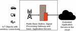
A sketch of a network deployment for cattle tracking is shown in Figure 1. Every cattle head carries one or multiple sensors which wirelessly transmit data packets either at regular intervals or when polled the by the radio Base Station (BS) shown.
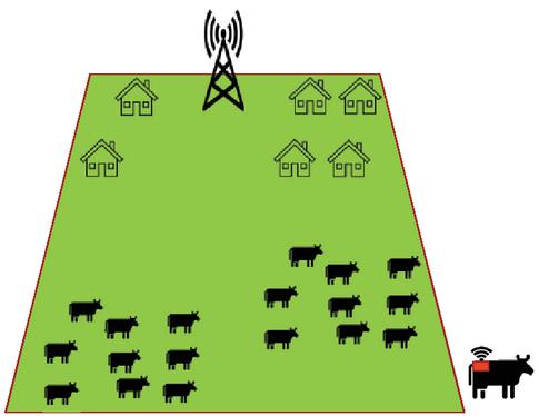
Figure 1 Schematic of IoT deployment for Smart Farming Cattle head equipped with wirelessly connected sensor nodes.

Figure 2 Schematic network architecture for IoT applications.
A basic schematic of a three-layer deployment architecture is shown in Figure 2 [2]. A fixed Base Station (BS) or a Gateway controls the IoT (mobile) nodes within its coverage area. The up-link (UL) messages transmitted by the IoT nodes are pre-processed by the Gateway and forwarded to the application server. Any downlink (DL) command or node activation messages generated by the application server are formatted by the Gateway to fit the radio transmission protocol used by the application.
The fixed infrastructure (mostly the Gateway and Application Servers) are powered by mains whereas the IoT mobile nodes are to a very large extent are battery powered and thus have a limited lifetime.
Availability of low-cost long life IoT nodes and the total cost of fixed infrastructure per unit coverage area are two important criteria for the viability of an IoT application. More technically, this translates into the need of protocols with high energy efficiency and high spectral efficiency.
Energy efficient protocols should be suitable for satisfying the double requirement of maximizing the Gateway coverage range and of allowing DTx (Discontinuous Transmission) mode of operation of the IoT nodes. This is achieved by minimizing their “duty cycle” which is essential for long battery life. Spectrally efficient protocols maximize the system throughput per unit bandwidth thus allowing simultaneous operation of large number of active IoT nodes in a given coverage area.
The objective of this article is to discuss specific IoT connectivity protocols which efficiently fit the criteria mentioned above.
The rest of this article is organised as follows. Section 2 presents a summary of the vast variety of IoT connectivity protocols. Subsection 2.1 describes the details of a widely deployed Low Power Wide Area Networking (LPWAN) protocol namely SigFox. Subsection 2.2 presents the performance figures on coverage range and traffic capacity (IoT node density) of this protocol. Section 3 concludes the paper.
2 IoT Connectivity Protocols
Table 1 Classification of Connectivity Solutions for IoT applications
| Example | |||
| Connectivity Solutions | Coverage Range | Technologies | Remarks |
| Wireless Personal Area Networks (WPAN) | Short Range (10 m to 100 m) | Bluetooth, ZigBee, Wireless HART, Thread | Low Transmit power nodes |
| Wireless Local Area Networks (WLAN) | Short / medium range (100 m to 1 km) | IEEE 802.11 a/b/n/ac/ah | Medium (Low) Transmit power nodes |
| Wireless Neighbourhood Area Networks (WNAN) | Medium range upto 10 km | Wi-SUN; ZigBee NAN | Medium (High) Transmit power nodes |
| Wireless Wide Area Networks (WWAN) | Long range higher than 10 km | Cellular 2G/3G Narrow Band LTE (MTC) and 5G | Medium (High) Transmit power nodes |
| Special Case – LPWAN – Low Power Wide Area Networks | Claimed long range much longer than 10 km | SigFox, LoRA, | Combined advantage of low Tx power and long coverage range |
Table 1 lists the wide variety of IoT connectivity protocols classified as per the BS/Gateway/Access Point coverage range [2]. The application domains, radio interface designations and some example protocols of Wireless Personal Area Networks (WPAN), Wireless Local Area Networks (WLAN), Wireless Neighbourhood Area Networks (WNAN) and Wireless Wide Area Networks (WWAN) are listed.
The BS/Access Point transmit power (Tx PWR) is one of the major distinguishing parameters between these different families. Generally speaking, the Tx PWR of an WWAN BS would be in the range of 10s of Watts whereas the Tx PWR utilised by a WPAN or WLAN access point would be limited to 10 s of mWs.
The special case of two LPWAN technologies, considered suitable for Smart Farming applications, is also listed in Table 1. The radio interface of these systems have been designed to achieve the twofold advantage of WWAN type coverage range with WLAN type Tx PWR.
2.1 LPWAN Connectivity Technology – SigFox
A typical SigFox network is deployed as a Single Frequency Network (SFN) using a Radio Frequency (RF) channel of 200 kHz bandwidth in the 868 MHz range [3]. The exact value is a function of allocation of the unlicensed Industrial Scientific and Medical (ISM) band in the zone/country of deployment.
A sizeable percentage of the SigFox deployments operate mainly in the UL data collection mode. SigFox Gateways are deployed to ensure an overlapping coverage. Data bursts transmitted by the IoT nodes in cell border areas can be simultaneously received by up to three Gateways. This offers spatial diversity advantage for range improvement.
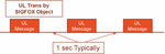
The timeline of an UL and DL message exchange in SigFox is presented in the schematics in Figures 3 and 4 respectively.

Figure 3 Uplink message transmission in SigFox.
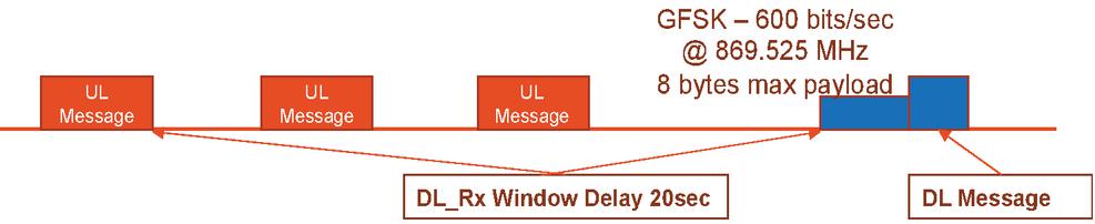
Figure 4 Downlink message transmission in SigFox.
A cycle starts with the transmission of an UL messages repeated three times at 1 sec interval as shown. The correct reception of the UL message by a Gateway can be followed by the transmission of a DL message depending on the application.
The UL data burst can contain up to 12 bytes of user payload and additionally has 4 bytes of Preamble, 2 bytes of Frame Synchronisation, 4 bytes of device identifier, a Hash code for authentication and 2 bytes for CRC. The burst is transmitted as a BPSK modulated binary sequence @ 100 b/sec in the form of an Ultra Narrow Band (UNB) signal of 100 Hz bandwidth in a randomly selected frequency interval within the 200 kHz bandwidth of the RF channel deployed in the Gateways.
Cost and energy efficiency of the SigFox objects (the IoT nodes) form the major drivers for the specifications of its radio interface. Its characteristics [2–4] are listed below:
• Random Frequency and Time Division Multiple Access (RFTDMA)
∘ High energy efficiency for IoT nodes which can transmit without any pre-sensing using Aloha protocol.
∘ No beacon signal and/or timing synchronisation between the Gateway and IoT nodes is required.
• Receiver Diversity Mechanism
∘ Three-fold transmission (repetition diversity)
∘ Frequency diversity through transmission of bursts by IoT nodes in randomly chosen 100 Hz bands.
∘ Spatial diversity through overlapping coverage for the IoT nodes at cell edge.
• Signal transmitted by IoT objects
∘ BPSK modulated @ 100 b/sec
∘ Signal bandwidth 100 Hz
∘ + 14 dBm Tx PWR
∘ Typical Tx oscillator accuracy +/- 20 ppm.
∘ Burst to burst frequency hopping to satisfy the requirements of the unlicensed ISM band.
• Gateway receiver processing
∘ FFT in the 192 kHz bandwidth followed by energy detection in the time-frequency bins as per the signal format.
∘ Signal demodulation and decoding in the 100 Hz band
∘ Diversity combining and best gateway selection
2.2 SigFox Performance Analysis
The Gateway coverage range and the system throughput (manageable IoT node density) are the two performance parameters of interest.
2.2.1 SigFox Gateway Coverage Range
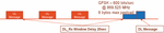
Following Tx/Rx parameters [2, 4] need to be considered for calculating the Gateway coverage range:
SigFox Object Transmit
– Tx PWR 14 dBm
– Tx Antenna Gain 0 dB
– Tx Signal Bandwidth 100 Hz
SigFox Gateway Receive
– Rx noise floor in 100 Hz –154 dBm (Calculated)
– Rx Antenna Gain 9 dB (implementation dependent)
– Rx Noise Figure 8 dB (implementation dependent)
– Rx Diversity Gain 3dB (implementation dependent)
– Signal/Noise threshold for acceptable BER 6 dB (implementation dependent)
The “system gain” or the available “Maximum Coupling Loss” (MCL) is
The coverage as per the applicable Okumura-Hata propagation model would be about 15 km for an urban deployment and could be 60 km for rural deployment. However, it is mandatory to respect certain deployment conditions like Gateway antenna height for achieving the very optimistic coverage range in rural deployment. Line of sight (LoS) propagation of radio waves at the deployment frequencies mentioned above is conditioned by the earth curvature.
2.2.2 SigFox Traffic Capacity Evaluation
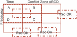
Due to the Aloha mode of operation of the RFTDMA protocol, bursts transmitted by the IoT nodes are prone to collisions at the Gateway receiver antenna. Figure 5 shows the time-frequency grid [5] of a Gateway receiver. Bursts arriving fitting well in time-frequency bins A, B, C and D represent a conflict free situation. However, all the received bursts covering more than one time-frequency bins in ABCD can generate collisions and hence hamper good detection and reduce the system throughput.
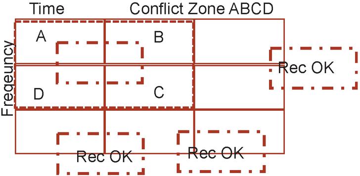
Figure 5 Time Frequency Grid at the Gateway Receiver [5].
Actually, the RFTDMA protocol operates as a 2-dimension Aloha protocol as compared to the 1-d (time only) operation of the classic Aloha protocol [5]. Both the transmission time instant and the 100 Hz frequency interval are randomly selected in the RFTDMA protocol whereas the transmission time instant is the only consideration in case of the classic Aloha protocol.
Figure 6 shows the throughput performance of 2-d Aloha protocol with Poisson distributed packet arrivals from IoT nodes [5]. A Tx oscillator stability of 20 ppm is assumed for these simulations. This is justified by the fact that the low-cost SigFox objects are built with ordinary watch crystal oscillators and that no arrangements for time synchronisation are available in the system.
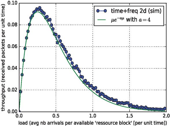
Figure 6 Throughput of 2-d Aloha protocol for poisson distributed packet arrivals simulations vs analysis [5].

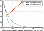
Figure 7 Burst detection probability for 3-fold repetition diversity [5].
Another interesting aspect is the effect of repetition diversity on burst collision rate and system throughput [5]. Figure 7 shows that the 3-fold repetition diversity brings an improvement in the burst detection probability at the cost of some degradation in throughput per number of active object nodes in the system.
Overall, the system throughput depends on the assumed Tx oscillator accuracy and the distribution of IoT node burst arrivals. Additional receiver signal processing algorithms such as interference cancellation between colliding bursts have been studied for throughput improvement.
3 Conclusions
LPWAN connectivity technologies satisfy the cost and energy efficiency requirements of applications such as Smart Farming e.g. for cattle tracking over vast coverage areas. The advantages of two features of the SigFox radio interface namely the uplink UNB transmission by simplified nodes and the RFTDMA protocol are instrumental in achieving these goals. Effectively, UNB signal transmission coupled with FFT based receiver processing in the Gateways offer very favourable uplink budget for very long-range coverage. The 2-d Aloha based RFTDMA protocol provides energy efficient operation for simplified IoT nodes coupled with moderately high system throughput.
Acknowledgements
• Dr Cédric Adjih of INRIA, France for 2-D Aloha Design and evaluation
• Dr Ramjee Prasad and Dr Singh for the opportunity to present this work at the events at IIT Ranchi and BITS Sindri.
References
[1] Ala Al-Fuqaha, Mohsen Guizani, Mehdi Mohammadi, Mohammed Aledhari, and Moussa Ayyash. Internet of Things: A Survey on Enabling Technologies, Protocols, and Applications. IEEE Communication Surveys & Tutorials, Vol. 17, No. 4, pp. 2347–2376; Fourth Quarter 2015.
[2] Vinod Kumar Lecture notes on IoT Protocols, 2017.
[3] Sigfox ETSI Mode White Paper. Rev – V 5.0; November 2018.
[4] Claire Goursaud, Jean-Marie Gorce. Dedicated Networks for IoT: PHY/MAC State of the Art and Challenges. EAI endorsed Transactions on Internet of Things, 2015.
[5] Cédric Adjih On Evaluation of RFTDMA traffic performance. Private communication. 2016.
Biography

Vinod Kumar has 35 years of R&D experience in mobile communications. During his 27 year tenure in Alcatel-Lucent he initiated and contributed to research projects in 2G-5G technologies – GSM, GPRS, EDGE, UMTS, HSPA, LTE, LTE A, IoT. He was also involved in standardisation, marketing support and in Patent Management related to above technologies. He contributed to multiple international projects (EC FP6, FP7), acted as Evaluator in EC H2020, ANR and Technical Auditor for CELTIC. He holds Secretary and Treasurer positions in Wireless World Research Forum (WWRF).
Dr Kumar has been Visiting Professor for 25 years for graduate courses in mobile communications in ENST (IMT Paris-Tech), CENTRALESUPELEC, ISEP, EURECOM in France and in MNIT in India. He was Associate Professor at the Université de Marne la Vallée in France for six years. He acted as member of Industrial Advisory Board of CTIF Denmark, of Conseil Technique of SUPELEC-France and of the joint INRIA-Bell Labs research lab.
He has widely lectured on 5G and IoT at IEEE and WWRF events, has been guest editor, referee for IEEE publications and PhD guide and examiner with CentraleSupelec and INRIA. He has 80 technical publications and 33 patents.
Journal of Mobile Multimedia, Vol. 17_1-3, 455–464.
doi: 10.13052/jmm1550-4646.171323
© 2020 River Publishers