Inspection Mobile Robot’s Control System with Remote IoT-based Data Transmission
Yuriy Kondratenko1, Oleksandr Gerasin2,*, Oleksiy Kozlov1, Andriy Topalov2 and Bohdan Kilimanov2
1Intelligent Information Systems Department. Petro Mohyla Black Sea National University, Mykolaiv, Ukraine
2Computerized Control Systems Department, Admiral Makarov National University of Shipbuilding, Mykolaiv, Ukraine
E-mail: y_kondrat2002@yahoo.com; oleksandr.gerasin@nuos.edu.ua; kozlov_ov@ukr.net; topalov_ua@ukr.net; bkilimanov@gmail.com
*Corresponding Author
Received 17 November 2020; Accepted 19 March 2021; Publication 18 June 2021
Abstract
The article presents the main stages of the development of remote control system for the inspection mobile robot operating on inclined ferromagnetic surfaces. The mobile robot remains on the surface and moves along working areas using separate clamping permanent magnets and caterpillars. The focus is on the control system’s architecture and remote data transmission based on Internet of Things technologies. Features of non-expensive Arduino Uno and WeMos D1 R2 mini microcontrolled development boards, cloud service Blynk, as well as multi-tab Android application interactions are revealed at the inspection mobile robot movement on the inclined surface. Experimental results of the proposed system show a good compatibility of chosen hardware, user-friendly human-machine interface and high mobility for future research of modern control algorithms at Internet of Things approach implementation for the extreme robotics.
Keywords: Internet of Things, remote data transmission, control system, inspection mobile robot, cloud service, Android application.
1 Introduction
In recent years, the Internet of Things (IoT) technology has become widely demanded and quite promising in different industries, economics, transport and agriculture [1–4]. Furthermore, the synergy of the Internet of Things and Robotics, that is now called as the “Internet of Robotic Things” (IoRT), is a rapidly evolving technology [5–7]. The IoRT combines all devices that receive various kinds of data from own sensors and external sources as well as use other tools (e.g., clouds) for data processing and decision making in order to interact with the surrounding physical world [8]. For example, the paper [9] presents the development and implementation of heterogeneous robotic arm with 5 DoF that implements computations in Cloud Robotics with additional libraries, share data between arms as well as perform data analysis and learning. In turn, the social robot is described in [10], which uses clouds, analyzes data from Wearables, determines the ways of movement and analyses which robotic tasks need to be implemented. Also, a number of robots are capable to displace themselves [11–13]. Some of these mobile robots may be included into another group of IoT – the Internet of Mobile Things (IoMT), i.e. drones self-driving cars and other unmanned autonomous vehicles [14–16]. They should have an ability to effectively consume energy, securely access the Internet through different networks as well as continue safe operating in the absence of Internet connection [17]. Since, different types of mobile robots often can’t use wired Internet connection and power cable, the following IoMT functions are essential for them: (a) establishment of secure wireless connection, (b) using of suitable protocols for connections with limited bandwidth or inconstant connections, (c) using of energy-efficient transmitters and approaches, (d) performing of complicated computations in clouds for energy saving [18].
So, an agriculture wireless mobile robot for performing different operations on the field, such as pest control and moisture sensing is designed in [19]. It uses the IoT approach for performing a remote control and uses camera and other sensors. The paper [20] considers the development of the fire fighting mobile robot that can get alert messages from its IoT sensors, moves to the fire location, performs all necessary firefighting actions as well as sends video stream of fire location to the fire safety officers. An algorithm for finding the shortest collision-free path for mobile robots is developed in [21]. It can be implemented for numerous mobile robots that operate in an automatic warehouse for their coordination via the cloud, transportation of goods marked with QR code or RFID. In turn, the paper [22] describes the development of the robot for cherry tomato harvesting. The authors combined the computer vision with fuzzy logic approach to implement gently harvesting of tomatoes with correct definition of their maturity. In addition, the surveillance mobile robot developed and presented in [23] has a non-expensive NodeMCU board that is enough powerful to stream even video and audio using IoT techniques for a reliable Internet connection.
Moreover, the direction of development of mobile robots with magnetic clamping devices and caterpillars is quite promising that is confirmed in a number of works [24–26]. These caterpillar mobile robots can move on inclined and vertical curved ferromagnetic surfaces for performing different types of technological operations, in particular inspection in shipbuilding, ship repair, agriculture and other industries, which can be dangerous to human health and life [27].
Thus, it is expedient to apply the IoT-based techniques for automation of the caterpillar mobile robots at moving along inclined and vertical ferromagnetic surfaces as extreme robotics objects, taking into account good experience in industrial IoT-systems for controlling different complex technical objects [2, 28]. In addition, implementation of wireless technology to such kinds of caterpillar mobile robots gives the opportunity of their remote control from any point of workspace as well as from anywhere in the world with the Internet access.
2 Caterpillar Mobile Robot with Separate Clamping Magnets For Vertical Movement
In previous studies [29, 30], the authors designed a scheme and considered the main properties of the mobile robot capable of moving vertically on inclined ferromagnetic surfaces, the main features of which are: two drive gear motors; separate clamping magnets; caterpillar propulsion.
The proposed mobile robot, which can be used for inspection, diagnostic, observation and research purposes, is physically implemented. The metal tracked transport platform of the factory design Doit T200 (it is shown in Figure 1) was chosen as the basis for the implementation of the experimental model of the inspection robot [31, 32]. The main advantage of this solution is that the body of this model is made of aluminum alloy, which makes it light and strong, as well as the presence of the ready-made caterpillar propulsions with clamping rollers and light plastic caterpillars.
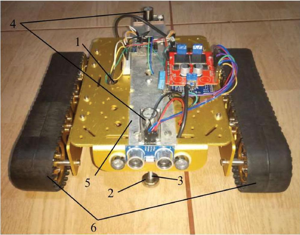
Figure 1 Experimental model of the caterpillar mobile robot for moving on ferromagnetic surfaces: 1 – gear motors, 2 – clamping permanent magnets, 3 – steel screws, 4 – spherical hinges, 5 – an additional rigid aluminum plate, 6 – rubber friction pads on the caterpillars.
The transport platform was modified to take into account the above design features of the mobile robot to ensure the ability to move and perform specified technological operations. Figure 1 shows the horizontal placement of the mobile robot’s model based on the caterpillar platform Doit T200, which is adapted to move on ferromagnetic surfaces [29, 30]. In particular, the platform has the following components:
• appropriate DC electric motors with gearboxes (gear motors marked “1” in Figure 1);
• individual clamping magnets 2 mounted on the long steel screws 3 with the ability to adjust the distance between the working ferromagnetic surface and the clamping surface of the magnets;
• spherical hinges 4 mounted on the additional rigid aluminum plate 5, which provide the possibility of free orientation of the greatest clamping force vector generated by the clamping magnet and the magnet relative to the working surface;
• rubber friction pads on the caterpillars 6 to increase the coefficient of friction of the surfaces of the caterpillars relative to the working ferromagnetic surface due to better adhesion to the working surface.
Further, let’s consider the development of the non-expensive control system with remote data transmission based on IoT technology for the presented inspection mobile robot.
3 Inspection Mobile Robot’s Computerized Control and Monitoring System based on the Internet of Things Technologies
The Internet of Things is a concept of a computer network of physical objects (“things”) equipped with built-in technologies for communicating with each other and with the environment. Recently, the organization of such networks has come to be seen as a phenomenon that can restart economic and social processes, as well as eliminate the need for human influence in the actions and operations. Filling the concept of IoT with multifaceted technical content and progressive practical solutions for its implementation are considered to be a steady trend in information technology, primarily due to the widespread use of wireless networks, the emergence of cloud computing, the transition to new Internet protocols, computer equipment and soft-adjustable networks development [33–35]. Common examples of the implementation of the IoT concept are the systems of “Smart Home”, “Smart Farm”, “Smart City”, “Smart Environment”, “Smart Transport”, “Smart Enterprise” and others [36–38].
In today’s industry advanced computerized monitoring and automatic control systems (usually with a hierarchical branched structure) based on data obtained during the execution of current technological operations in the real time [39] should be used for effective performing the robotic tasks with high energy and economic indicators. In addition, such systems should have a developed, highly integrated programming environment that is quite flexible and easy to extend, as well as flexible networking tools with the ability to connect to the online expert system for more detailed data analysis [30].
However, it is known that modern hardware for the implementation of mobile robots control systems in industrial performance (programmable logical controllers, data acquisition modules, output modules, etc.), as well as their software development environments are very expensive. Therefore, for research purposes it is advisable to use cheaper development tools to solve the design problem of the software and hardware, as well as the human-machine interface and experimental model of the considered computerized monitoring and automatic control system with remote data transmission based on Internet of Things technologies for the inspection mobile robot.
3.1 Structure of the Robot’s Control and Monitoring System with Remote Data Transmission
The proposed computerized system is built in variable configuration and includes both remote monitoring and control means with cloud technologies application. Its functional structure is shown in Figure 2.
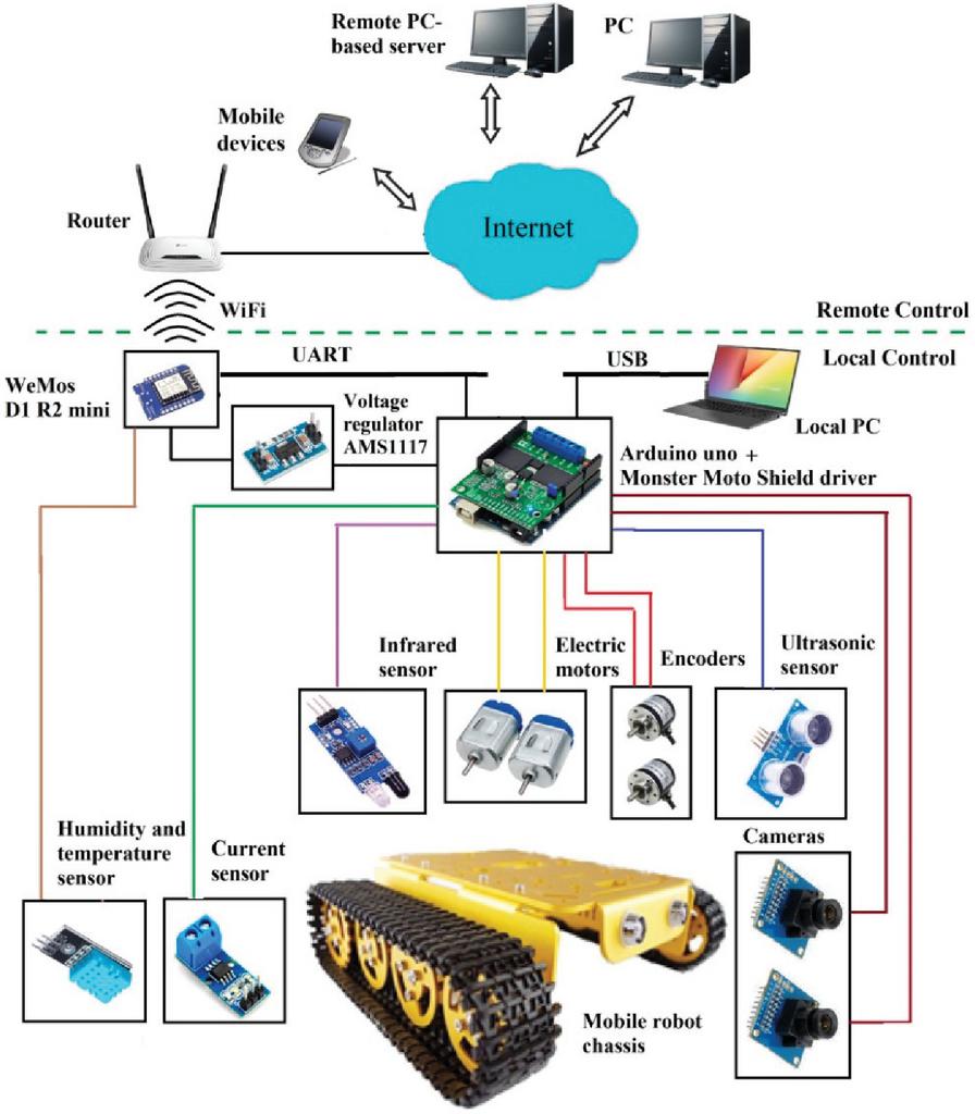
Figure 2 Functional structure of the IoT-based control system for the inspection mobile robot.
The offered computerized system has two main levels of automatic control and monitoring: local and remote. In turn, the local level presents three hierarchical levels of control and monitoring: the lower is the level of actuators and sensors, the middle is the control level and the upper is the operator level. The lower level includes inspection sensors, analog-to-digital converters, intermediate converters (if needed) and actuating devices or motors. The information about the state of the robot’s motors, ferromagnetic surface, obstacles or investigated objects is formed and transmitted by ultrasonic, infrared, current and temperature sensors, as well as encoders, cameras, etc. The actuators are used to execute the robot’s movement and to avoid the obstacles or manipulate different objects [40]. The types of devices at the lower level may significantly differ for different inspection tasks. In turn, the middle level has microprocessor-based development board (sometimes several boards are present) and the motors supply driver. This level processes data from the sensors, converters and generates corresponding control signals (commands) for the actuating devices of the lower level. Pre-developed control algorithm defines corresponding control signals. An additional communication board or a hub may also be installed to coordinate the interaction of the main development board with the upper level. In turn, the upper level is responsible for monitoring, data acquisition and visualization of the received utility information from controller [30], as well for preliminary testing and debugging control programs with personal computer (PC).
Cloud technologies are used in the remote level for implementation of operator monitoring, control and database accumulation. The main aim of this level is to give access to mobile robot’s parameters, controlled coordinates and current values of settings via an Internet connection from any workplace in the world. It is desirable to display this information in the real time mode in virtual screens or specialized web-oriented software installed in the pre-defined control posts (the ability of the actuators and motors control is usually absent in industrial applications [30, 39]).
3.2 Hardware Solution Based on Development Boards
Hardware implementation of the proposed computerized control and monitoring system consists of the following main separate boards: ArduinoUNO, WeMos D1 R2 mini, levels converter 3.3–5V, Monster Moto Shield driver. A list of sensors for inspection mobile robot may be rather wide: laser, ultrasonic, water, humidity, temperature, fire, etc.
ArduinoUNO is a widespread development board that is used in different tasks from amateur homemade products to research projects [41, 42]. It is the embedded control unit in the system.
WeMos D1 R2 mini is an Arduino-compatible small development board [43]. The most important technical characteristics of this device are the following: high clock speed of the processor, the Wi-Fi module presence in the circuit board, type and amount of flash memory [43]. WeMos microcontrollers have recently become widespread in computer equipment, industry, and home appliances [44]. In addition, the controller has an ArduinoUNO form factor and works in most cases as an UNO, but has one huge advantage over the standard Arduino – it contains built-in Wi-Fi, so sketches can be updated wirelessly in this module. However, the disadvantages of WeMos D1 R2 mini are the difficulties with interruptions handling and the small number of analog ports (only one). A technically justified solution is the use of microcontrollers of the WeMos series to measure various parameters, signal processing, control of a large set of modern communication devices, various manipulators and robots [43, 44]. Therefore, ArduinoUNO and cloud service communication is established in the system due WeMos D1 R2 mini.
The Monster Moto Shield driver is chosen to supply the inspection mobile robot’s motors. Monster Moto Shield is based on the VNH2ASP30 chip which allows controlling both the speed and the direction of movement of the connected gear motors, as well as blocking the motors and reading the current consumption using analog pins [45].
Analog-to-digital converter can be used in case of the analog ports lack in the development board; ADS1115 board is often used to increase the number of analog ports [46]. In this case humidity and temperature sensor DHT11, as well as ultrasonic sensor HC-SR04 are directly connected to the ArduinoUNO and WeMos D1 R2 mini for testing remote data transmission by IoT-technology in extreme robotics application. The rules for connecting the main system’s components are given in Table 1 to control the movement of the inspection mobile robot.
Table 1 Matching and appointment of ports of the involved system’s boards
| ArduinoUNO Ports | Monster Moto Shield Ports |
| A0 | State of A1 and B1 keys |
| A1 | State of A2 and B2 keys |
| A2 | Analog output of the current value of the first driver |
| A3 | Analog output of the current value of the second driver |
| 2 | Encoder of the 1st motor |
| 3 | Encoder of the 2nd motor |
| 4 | Control of A2 key |
| 5 | PWM control of the first driver |
| 6 | PWM control of the second driver |
| 7 | Control of A1 key |
| 8 | Control of B1 key |
| 9 | Control of B2 key |
| 12 | Signals receiving from the rangefinder HC-SR04 |
| 13 | Sending ranging signals to the HC-SR04 |
| WeMos D1 R2 Mini Ports | Appointment |
| D8 | Measurement of temperature and humidity with a DHT11 |
Figure 3 shows the connection diagram of the individual components of the system for the mobile robot’s speed control. The total power of the driver and WeMos D1 R2 mini is 9V. An additional voltage converter AMS1117 is used for stable 3.3V supplying WeMos D1 R2 mini.
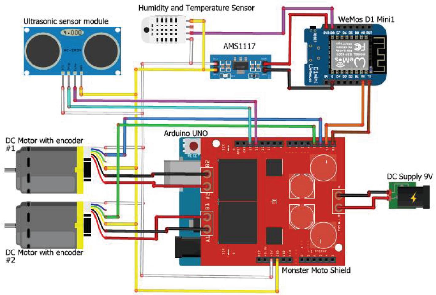
Figure 3 The connection diagram of separate components of the mobile robot’s movement control system.
3.3 Software Means for IoT-based Remote Data Transmission
For developing the control algorithms of the mobile robot’s control system the authors used Arduino Software (IDE) [47]. This program simplifies the working process when coding, debugging and flashing microcontrollers of the development boards. It has several advantages over other program products, such as: (a) clear and simple programming environment, (b) large number of expansion boards and (c) free distribution.
Remote data transmission is implemented using the concept of IoT, cloud service and Android application Blynk [48]. The authors developed a special multi-tab interface (Figure 4, a, b) for the remote control and monitoring system of the given inspection mobile robot. The main window (Tab 1 in Figure 4, a) of the developed interface consists of speedometer indicators for displaying the motors speeds, LED indicator for displaying the connection of the development board to the smartphone, one button to start the connection and the virtual movable circle shaped joystick for setting moving course angle and speed value of the caterpillar mobile robot.
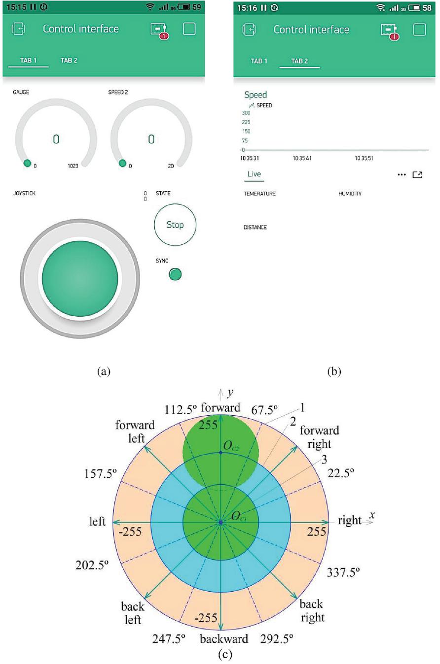
Figure 4 Multi-tab interface in the Blynk application (a, b) and the scheme of the virtual joystick movement in the working area with the outer (1), working (2) and movable (3) circles with angular values of sectors (c).
The current position of the joystick corresponds to a virtual PIN with two parameters (x and y coordinates). This virtual PIN is necessary for synchronization of the Android application with the main control program in the microcontroller installed on the ArduinoUNO board, course angle and speed value determination based on the processing a circle’s given position. Tab 2 shows the motors speed changes in graphical view (Figure 4, b). Temperature, humidity and the distance to the obstacle are shown in a numerical format.
Figure 4, c shows movable, working (internal) and outer circles which are the parts of the virtual joystick. The movable circle is the border of the joystick circle that is inside the outer circle and can move freely within it. The working circle limits the boundaries of the center of joystick’s circle working area, so the movable circle reaches the edge of the outer circle, the center of the movable circle moves to the edge of the working circle. Thus, the movable circle, visually, moves inside the outer circle without leaving it.
The center of the work area is in the center of the rectangular Cartesian coordinate system. Two coordinate axes x and y (the axes in which the center point of the moving circle will move) are chosen with the beginning points in the center of the working circle (Figure 4, c). There are two basic states of the virtual joystick: centered and deviated. The central (initial) position of the joystick (point O in Figure 4, c) corresponds to the resting state of the robot (it doesn’t move). Considering that the outer circle has a diameter of 511 pixels, the coordinates of the point O is the middle of the diameter of the outer circle (255; 255). The virtual joystick is automatically backed to the initial position if a user does not touch it. There are eight possible directions of movement (course angles) that can be given to the robot: forward, backward, right, left, forward right, forward left, back right, back left – splitting the work area by 45 considering from the central angle. So, the placement of the joystick’s center in one of the eight obtained segments means the movement in this direction. For example, the center of the joystick in the point O in Figure 4, c corresponds to the direction “Forward”.
The program for remote control of the caterpillar mobile robot moving on the ferromagnetic surface includes a few functions for motion implementation and synchronization processing of the Blynk application with the Blynk cloud server and the WeMos D1 board with the Blynk cloud server. The first function synchronizes the Android app and the mobile robot (ArduinoUNO through WeMos D1 R2 mini) and indicates a status of connection with LED. The button in application sends a request to establish connection. The second function receives the Cartesian coordinates of the joystick x and y from the smartphone application and converts them into polar ones, i.e. the radius r (corresponds to the given value of speed module) and the angle are determined by applying the trigonometric functions of sine and cosine [49]. The third function defines one of eight movement directions according to the Figure 4, c.
The block diagram of the robot’s movement direction defining is shown in Figure 5 (degree symbols aren’t shown in the condition blocks, minimal value for speed setting is more than 20 points, the boundaries of the directions are determined by Figure 4, c). The calculated values of speed and course are the input control coordinates to the mobile robot’s spatial motion automatic control system [50].
The Blynk Android application is able to operate on wired and wireless networks. The mobile robot’s remote control occurs due to WiFi communication. At the initial stage of the design the Android app and the development board exchange data only if the board and the smartphone are connected to a shared local access point. The system is already configured to remote control the mobile robot via the global Internet: the WeMos D1 R2 mini board – via the router and the mobile device with the Android app – via 4G. The high security level of the proposed system is provided by several authorization stages and software means: (a) specification of the name of the network and the access key in the control program of WeMos D1 R2 mini; (b) entering login and password in Blynk application or confirmation of Facebook account; (c) correct identifier of the project (authorization token) at Blynk webserver connection. The development board and the Android application are synchronized after applying power to the board and starting the application (the corresponding LED “SYNC” indicates this event in the application). The proposed computerized system provides the remote control and monitoring of the inspection caterpillar robot from any place in the world at the presence of the Internet access, e.g. at the insufficient experience of the post operator [30].
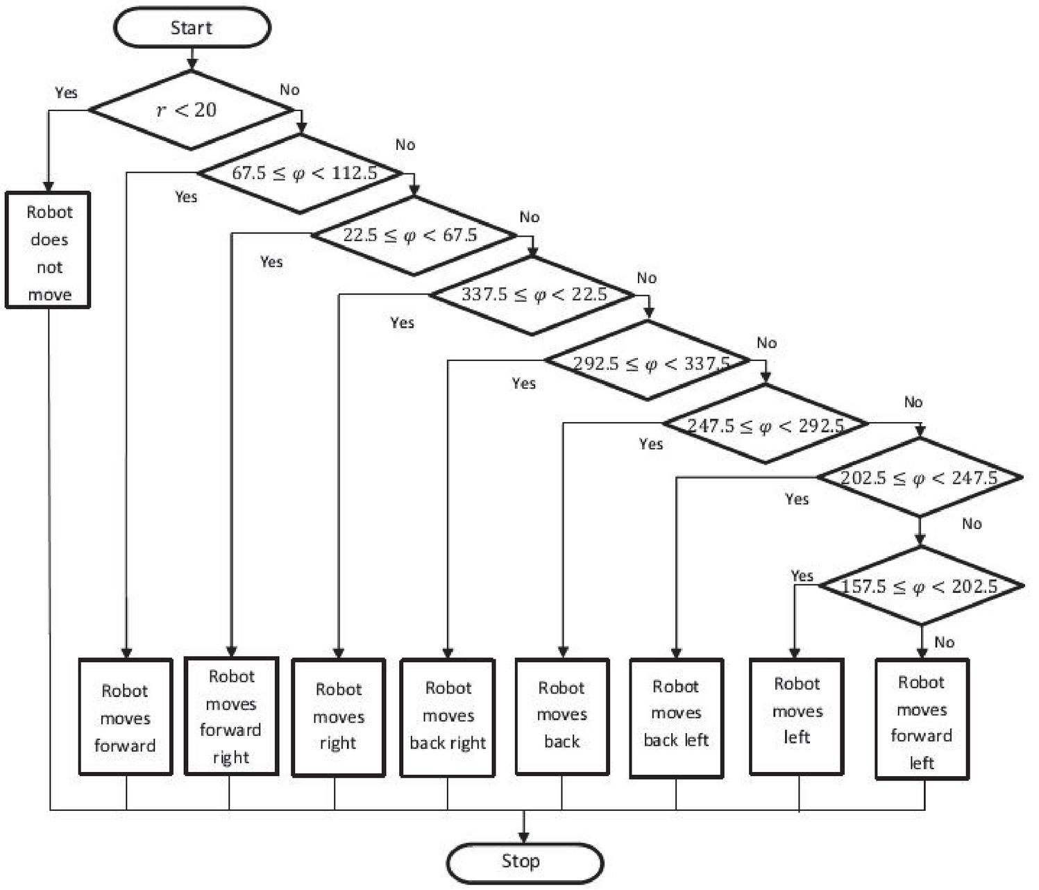
Figure 5 Block diagram of the algorithm that determines the movement direction of the mobile robot.
4 Experimental Testing of the Proposed System
The effectiveness of any theoretical project should be confirmed by its experimental implementation. This is especially true for extreme robotics related to the mobile robots, that can move vertically, and their control systems. Moreover, it is quite relevant to consider the results of the modern technologies usage for remote control based on the concept of the Internet of Things, which is currently developing rapidly and has broad prospects for implementing and improving the efficiency of remote monitoring and control [39].
The spatial position of the experimental inspection caterpillar mobile robot with the selected hardware on the ferromagnetic surface is presented in Figure 6. Supply and communication lines run along the bottom and from above the robot’s hull in accordance with the mentioned above configuration. The mobile robot with its control system is powered by wire, as well as the 9V battery can be used for increasing the robots mobility. The other control system components are lightweight and have a little effect on driving dynamics.
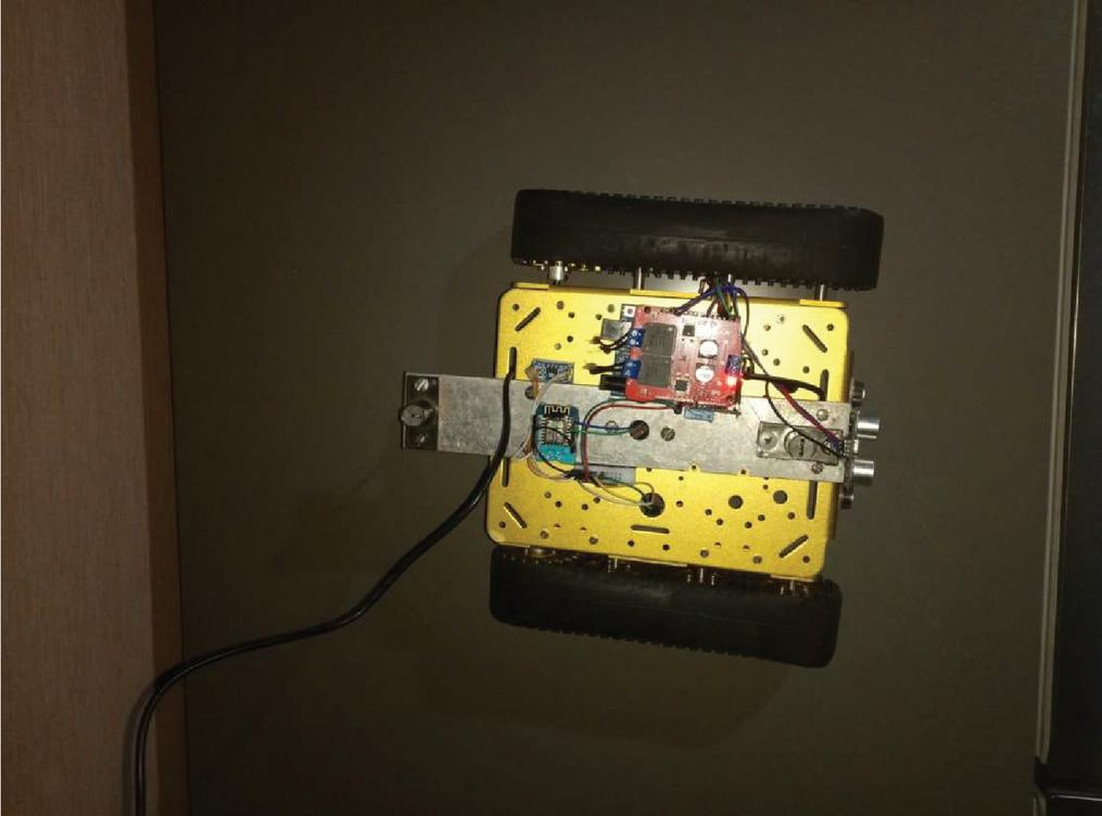
Figure 6 Placement of the caterpillar inspection mobile robot on vertical ferromagnetic surface (power is wired, control is wireless).
The developed multi-tab interface based on the Android application Blynk is shown in Figure 7 for the running robot. In turn, the main window of the running application is shown in Figure 7, a. There are two speedometer indicators which display the motors speed values. The correct connection of the Blynk to the WeMos D1 R2 mini is indicated by lighting “SYNC” LED indicator. The virtual movable joystick is displaced to the [14; 131] coordinates, that corresponds to 90.1 of the set direction value, so the robot has to move “forward” direction in accordance with the algorithm in Figure 5. The calculated value of the setting robot’s speed is the same for both motors after reaching the given course angle. As they are consonant controlled, so the same speed values from the encoders are shown in Figure 7, a.
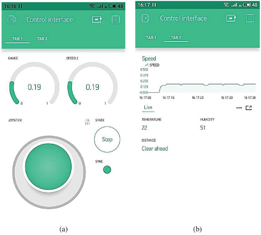
Figure 7 Multi-tab interface in action: current speed values and virtual joystick position in Tab 1 (a), speed graph with concordant control of two motors and information from inspection sensors in Tab 2 (b).
The Blynk application has a possibility to display the motors speed changes in details (for the robot’s starting in Tab 2, Figure 7, b) with the time coordinate axis that is very convenient for further control indicators determination, such as: transient time, the static error, overshoot, oscillation [50]. As well as, the inspection sensory information (current temperature, humidity and the distance to the obstacle) is presented in Figure 7, b. The developed graphic interface of the proposed control system for the inspection mobile robot allows the joint setting of the given movement direction and speed value, displaying the real-time sensory information in different adjustable views and tabs. Also, the operator (user) has the opportunity to send the separate points of measured values in .csv format to his registered e-mail for further processing.
The proposed system is of particular interest, since it can be used in the extreme robotics to validate the mathematical models, adjust the control devices, test the communication signals, etc. So, let’s consider an example of using the developed system to analyze the adequacy of the mathematical model of the inspection caterpillar mobile robot able to move on the ferromagnetic surfaces.
In [50] the mathematical model of the industrial caterpillar mobile robot with clamping magnets is considered in details. The model was transformed for the experimental sample, presented in Figure 6, and the transients were simulated by the computing software (step of simulation – 0.1 s). Let’s compare experimental and modeling results, which are presented in Figures 8 and 9. There are three modes of the robot’s power: 30, 50 and 80% of maximum power value and two angles (0 and 30) of the ferromagnetic surface inclination. Both figures use the following notation: V30, V30, V50, V50, V80 and V80 – experimental and modeling speeds of the mobile robot at 30, 50 and 80% of the motors supplying power, respectively. Visual comparison of experimental and modeling graphs shows their similar trend and good qualitative compliance.
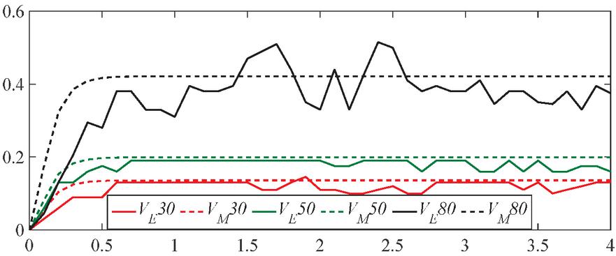
Figure 8 Detailed step up transients of the mobile robot’s speed when running horizontal ferromagnetic surface at different motors’ supplying power: 1 – 30%; 2 – 50%; 3 – 80%.
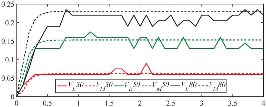
Figure 9 Detailed step up transients of the mobile robot’s speed when running 30 inclined ferromagnetic surface at different motors’ supplying power: 1 – 30%; 2 – 50%; 3 – 80%.
The analysis of the adequacy of the synthesized mathematical model of the mobile robot able to move on inclined ferromagnetic surface on the basis of the equations from [50] was carried out using the methods of estimating the hypotheses of mathematical statistics, namely:
(1) the sum of squared estimate of errors (SSE), which shows the total deviation of the values of the mathematical model V(t) from the corresponding values of the experimental data V(t):
| (1) |
(2) the root-mean-square error (RMSE) is an estimate of the standard deviation of the random component between the data of the synthesized regression model and the experimental values
| (2) |
Based on the obtained statistical data (Table 2), we can conclude that the SSE and RMSE decrease when the robot moves up the hill and increase when the robot’s supplying power increases (due to PWM settings). Such results indicate the presence of some regularity between the rate of change of the measured value of the robot’s speed V(t) and the required frequency of data transfer. To further improve the accuracy of the mobile robot’s mathematical model, it is necessary to consider the data transferring delay and the speed sensor measurement error, as well as to use a larger number of the experimental points and the modes [51].
Table 2 Analysis of statistical indicators in different modes of the mobile robot operating
| Statistical Indicators and Angle of Inclination | ||||
| SSE | RMSE | |||
| Supplying Power | 0 | 30 | 0 | 30 |
| 30 % | 0.0199 | 0.0015 | 0.0220 | 0.0061 |
| 50 % | 0.0220 | 0.0127 | 0.0232 | 0.0176 |
| 80 % | 0.2482 | 0.0421 | 0.0778 | 0.0320 |
So, the sensory information and graphs of the transients make it possible to validate the theoretically obtained results at conducting research in the field of identification (clarification of the theoretical model [50, 51]), automatic control and monitoring in robotic systems and extreme robotics complexes. Moreover, the proposed system poses an additional research task – the determination of the communication continuity for the mobile robot. In particular, the dependence between sensors’ acquisition frequency and accuracy of receiving data may be found for the developed system configuration. In addition, the embedded computational data filtering algorithms will be tested for preliminary processing of sensory information in future research.
5 Conclusions
The authors proposed the experimental model of inspection mobile robot operating along inclined ferromagnetic surfaces and its control system with remote data transmission based on the Internet of Things technology. The functional structure and main features of the control system for the mobile robot movement have been considered from the side of IoT-approach application and non-expensive technical solutions. The proposed system makes it possible to control the robot’s movement along surfaces in different spatial positions from any Internet access point in the world after the authorization procedure, e.g. for providing remote access to the monitoring and control by the outside advisors and experts at the insufficient experience of the post operator. The practical example of using the developed system is considered to analyze the adequacy of the mathematical model of the mobile robot. The statistical indicators (SSE and RMSE) show different adequacy of the robot’s mathematical model at varies motor’s power and angle of inclination of the ferromagnetic surface. So, the further research should be conducted towards the refinement of the mathematical model, the practical implementation of different advanced control methods, communications conditions and data filtering algorithms in the proposed control system of the inspection mobile robot.
List of Abbreviations
| IoMT | – | Internet of Mobile Things; |
| IoRT | – | Internet of Robotic Things; |
| IoT | – | Internet of Things; |
| PC | – | Personal Computer; |
| QR code | – | Quick Response Code; |
| RFID | – | Radio Frequency Identification. |
References
[1] O. Vermesan, P. Friess, ‘Digitising the industry – Internet of Things connecting the physical, digital and virtual worlds’, River Publishers, 2016.
[2] Y. Kondratenko, O. Kozlov, O. Korobko, A. Topalov, ‘Complex industrial systems automation based on the Internet of Things implementation’, in: Bassiliades N. et al. (eds) Information and Communication Technologies in Education, Research, and Industrial Applications (ICTERI 2017). Communications in Computer and Information Science, volume 826, Springer, Cham, 2018.
[3] Sh. Li, H. Wang, T. Xu, G. Zhou, ‘Application study on Internet of Things in environment protection field’, Lecture Notes in Electrical Engineering volume, Lecture Notes in Electrical Engineering, 2011.
[4] Y.P. Kondratenko, O.V. Kozlov, A. M. Topalov, O.V. Korobko, O.S. Gerasin, ‘Automation of control processes in specialized pyrolysis complexes based on industrial Internet of Things’, in: Vyacheslav Kharchenko, Ah Lian Kor, Andrzej Rucinski (Eds.), Dependable IoT for Human and Industry. Modeling, Architecting, Implementation. Series in Information Science and Technology, River Publishers, Gistrup, Delft, 2018.
[5] Y. Masuda, A. Zimmermann, S. Shirasaka, O. Nakamura, ‘Internet of Robotic Things with digital platforms: digitization of robotics enterprise’, International KES Conference on Human Centred Intelligent Systems, KES-HCIS 2020; Split; Croatia; 17 June 2020, volume 189, 2020.
[6] V. S. Prabhu, R. M. Abinaya, G. Archana, R. Aishwarya, ‘IoT-based automatic library management robot’, 1 International Conference on Frontiers in Smart Systems Technologies, ICFSST 2019, Chennai, India, volume 3, 2019.
[7] N. Seenu, R.M.K. Chetty, K.M.A. Krishna, T. Srinivas, R.G.P. Raj, ‘A mechatronics design approach of a low-cost smart reconnaissance robot’, 6th International Conference on Information System Design and Intelligent Application, INDIA 2019, Visakhapatnam, volume 134, 2019.
[8] P. Simoens, M. Dragone, A. Saffiotti, ‘The Internet of Robotic Things: a review of concept, added value and applications’, International Journal of Advanced Robotic Systems, 15(1), 2018.
[9] S. Arefin, E. Heya, T. Ashrafi, J. Uddin, ‘Real-life implementation of Internet of Robotic Things Using 5 DoF Heterogeneous Robotic Arm’, 2018 Joint 7th International Conference on Informatics, Electronics & Vision and 2018 2nd International Conference on Imaging, Vision & Pattern Recognition, Kitakyushu, Japan, 2018.
[10] P. Simoens, et al., ‘Internet of Robotic Things: context-aware and personalized interventions of assistive social robots (short paper)’, 2016 5th IEEE International Conference on Cloud Networking (Cloudnet), Pisa, Italy, 2016.
[11] D. Souto, A. Faiña, F. López-Peña, R. J. Duro, ‘Lappa: a new type of robot for underwater non-magnetic and complex hull cleaning’, IEEE International Conference on Robotics and Automation (ICRA), Karlsruhe, 2013.
[12] N.T.-T. Vu, L.X. Ong, N.H. Trinh, S.T.H. Pham, ‘Robust adaptive controller for wheel mobile robot with disturbances and wheel slips’, International Journal of Electrical and Computer Engineering, volume 11, Issue 1, 2020.
[13] M. Komori, T. Terakawa, ‘Omnidirectional mobile robot and vehicle, uninterrupted transmission system, intuitive operating method, and riding robotics: overview of research activities in vibration engineering laboratory in Kyoto University’, Mechanisms and Machine Science, volume 91, 2020.
[14] A. Salam, Q. Javaid, G. Ali, F. Ahmad, M. Ahmad, I. Wahid, ‘Flying sensor network optimization using bee intelligence for Internet of Things’, Intelligent Systems Conference, IntelliSys 2020, London, United Kingdom, volume 1252, 2020.
[15] P.P. Ray, K. Nguyen, ‘A review on blockchain for medical delivery drones in 5G-IoT era: progress and challenges’, 2020 IEEE/CIC International Conference on Communications in China, ICCC Workshops 2020, Chongqing, China, 2020.
[16] L. Bertizzolo, S. D’Oro, L. Ferranti, L. Bonati, E. Demirors, Z. Guan, T. Melodia, S. Pudlewski, ‘Swarm control: an automated distributed control framework for self-optimizing drone networks’, 38th IEEE Conference on Computer Communications, INFOCOM 2020, Toronto, Canada, 2020.
[17] Y. Kondratenko, ‘Robotics, automation and information systems: future perspectives and correlation with culture, sport and life science’, in Decision Making and Knowledge Decision Support Systems, Lecture Notes in Economics and Mathematical Systems, in: A. Gil-Lafuente, C. Zopounidis (Eds.), volume 675, Springer International Publishing Switzerland, 2015.
[18] A. Tkachenko, N. Brovinskaya, Y. Kondratenko, ‘Evolutionary adaptation of control processes in robots operating in non-stationary environments’, Mechanism and Machine Theory 18 (4), 1983.
[19] K.L. Kristina, O. Silver, W.F. Malende, K. Anuradha, ‘Internet of Things application for implementation of smart agriculture system’, International Conference on I-SMAC’ (IoT in Social, Mobile, Analytics and Cloud), Palladam, India, 2017.
[20] P. A. Raj, M. Srivani, ‘Internet of Robotic Things based autonomous fire fighting mobile robot’, IEEE International Conference on Computational Intelligence and Computing Research (IEEE ICCIC 2018), Madurai, India, 2018.
[21] J. L. Avila-Alonso, D. Lopez-Araujo, N. Alvarez-Jarquin, ‘Planning of collision-free trajectories for mobile robots using IoT’, IEEE International Autumn Meeting on Power Electronics and Computing (ROPEC), Ixtapa, Mexico, USA, 2018.
[22] L. Biqing, L. Yongfa, Zh. Hongyan, Zh. Shiyong, ‘The design and realization of cherry tomato harvesting robot based on IoT’, International Journal of Online and Biomedical Engineering (iJOE), 12 (12), 2016.
[23] D. Singh, A. Nandgaohkar, ‘IoT-Based Wi-Fi surveillance robot with real-time audio and video streaming’, in: Advances in Intelligent Systems and Computing, Lonere, India, 2019.
[24] H. Huang, D. Li, Z. Xue, X. Chen, S. Liu, J. Leng, Y. Wei, ‘Design and performance analysis of a tracked wall-climbing robot for ship inspection in shipbuilding’, Ocean Engineering, 131, 2017.
[25] O. Kermorgant, ‘A magnetic climbing robot to perform autonomous welding in the shipbuilding industry’, Robotics and Computer-Integrated Manufacturing, 53, 2018.
[26] G. Lee, J. Park, H. Kim, K. Seo, J. Kim, T. Seo, ‘Wall climbing robots with track-wheel mechanism’, Proceedings of the 3rd International Conference on Machine Learning and Computing (ICMLC 2011), Guillin, China, 2011.
[27] Y. Kondratenko, Y. Zaporozhets, J. Rudolph, O. Gerasin, A. Topalov, O. Kozlov, ‘Modeling of clamping magnets interaction with ferromagnetic surface for wheel mobile robots’, International Journal of Computing, 17 (1), 2018.
[28] Y.P. Kondratenko, O.V. Kozlov, O.V. Korobko, A.M. Topalov, ‘Internet of Things approach for automation of the complex industrial systems’, 13th International Conference on Information and Communication Technologies in Education, Research and Industrial Applications. Integration, Harmonization and Knowledge Transfer, in: Ermolayev, V. et al. (Eds), CEUR-WS, Vol-1844, Kyiv, Ukraine, 2017.
[29] O. Gerasin, O. Kozlov, G. Kondratenko, J. Rudolph, Y. Kondratenko. ‘Neural controller for mobile multipurpose caterpillar robot’, Proceedings of the 10th IEEE International Conference Intelligent Data Acquisition and Advanced Computing Systems: Technology and Applications (IDAACS), volume 1, Metz, France, 2019.
[30] O.S. Gerasin, A.M. Topalov, M.O. Taranov, O.V. Kozlov, Y.P. Kondratenko, ‘Remote IoT-based control system of the mobile caterpillar robot’, CEUR Workshop Proceedings, volume 2740, 2020.
[31] WD WiFi tank car chassis. Electronic resource URL: https://goo.su/1g2Q.
[32] Installation manual for T series Tank Chassis. Doctor of Intelligence & Technology (DOIT). 2016.
[33] S. Jeschke, C. Brecher, H. Song, D. Rawat. Industrial Internet of Things. Springer International Publishing, 2017.
[34] N. Sousa, J. V. V. Sobral, J. J. P. C. Rodrigues, R. A. L. Rabêlo and P. Solic, ‘ERAOF: A new RPL protocol objective function for Internet of Things applications,’ 2017 2nd International Multidisciplinary Conference on Computer and Energy Science (SpliTech), Split, 2017.
[35] M. Bottone, F. Palumbo, G. Primiero, F. Raimondi, R. Stocker, ‘Implementing virtual pheromones in BDI robots using MQTT and Jason’, 5th IEEE International Conference on Cloud Networking. Pisa, Italy, 2016.
[36] A. Kor, C. Pattinson, M. Yanovsky, V. Kharchenko, ‘IoT-enabled smart living. Technology for Smart Futures’, in: M. Dastbaz, H. Arabnia and B. Akhgar (Eds.), Cham : Springer, 2018.
[37] P. Markopoulos, J. Nichols, F. Paternò, V. Pipek, ‘Editorial: End-user development for the Internet of Things’, ACM Transactions on Computer-Human Interaction, volume 24, 2017.
[38] D. Russo, ‘Domotics and robotics’, Dolentium hominum, volume 84, 2014.
[39] Y. P. Kondratenko, O. V. Kozlov, O. S. Gerasin, A. M. Topalov, O. V. Korobko, ‘Automation of control processes in specialized pyrolysis complexes based on Web SCADA Systems’, Intelligent Data Acquisition and Advanced Computing Systems: Technology and Applications (IDAACS): Proceedings of the 9th IEEE International Conference. Bucharest, Romania, volume 1, 2017.
[40] Y. Kondratenko, A. Topalov, O. Gerasin, ‘Analysis and modeling of the slip signals’ registration processes based on sensors with multicomponent sensing elements’, The experience of designing and application of CAD systems in microelectronics (CADSM 2015), Lviv-Poljana, Ukraine, 2015.
[41] Arduino Uno Rev3. Arduino Official Store, URL: https://goo.su/32gO.
[42] G. A. Mutiara, P. Periyadi, A. D. Agnas, V. Darma, ‘Smart vest and monitoring system for airsoft sport – games using vibration sensor’, International Journal of Computing, volume 19, No. 2, 2020.
[43] Wemos D1 R2 and mini on the basis ESP8266. Electronic resource URL: https://goo.su/1FuV.
[44] T. Kusuma, M. Tirta Mulis, ‘Perancangan sistem monitoring infus berbasis mikrokontroler WeMos D1 R2’, Konferensi Nasional Sistem Informasi 2018. STMIK Atma Luhur Pangkalpinang, 2018.
[45] Monster Moto Shield. URL: https://goo.su/1fUw.
[46] 16-bit ADC module ADS1115. Electronic resource URL: https://goo.su/1Fuw.
[47] The open-source Arduino Software (IDE), Electronic resource URL: https://goo.su/32Gn.
[48] Blynk IoT platform, Electronic resource URL: https://blynk.io.
[49] O. Gerasin, Y. Zaporozhets, Y. Kondratenko, ‘Models of magnetic driver interaction with ferromagnetic surface and geometric data computing for clamping force localization patches’, IEEE Second International Conference on Data Stream Mining & Processing, Lviv, Ukraine, 2018.
[50] Y. Kondratenko, O. Kozlov, O. Gerasin, ‘Neuroevolutionary approach to control of complex multicoordinate interrelated plants’, International Journal of Computing, volume 18, No. 4, 2019.
[51] O. Brunetkin, K. Beglov, V. Brunetkin, O. Maksymov, O. Maksymova, O. Havaliukh, V., ‘Construction of a method for representing an approximation model of an object as a set of linear differential models’, Eastern-European Journal of Enterprise Technologies, volume 6, No. 2 (108): Information technology. Industry control systems, 2020.
Biographies

Yuriy Kondratenko is Doctor of Science, Professor, Honour Inventor of Ukraine (2008), Corr. Academician of Royal Academy of Doctors (Barce-lona, Spain), Head of the Department of Intelligent Information Systems at Petro Mohyla Black Sea National University (PMBSNU), Ukraine. He has received (a) the Ph.D. (1983) and Dr.Sc. (1994) in Elements and Devices of Computer and Control Systems from Odessa National Polytechnic University, (b) several international grants and scholarships for conducting research at Institute of Automation of Chongqing University, P.R.China (1988–1989), Ruhr-University Bochum, Germany (2000, 2010), Nazareth College and Cleveland State University, USA (2003), (c) Fulbright Scholarship for researching in USA (2015/2016) at the Dept. of Electrical Engineering and Computer Science in Cleveland State University. Research interests include robotics, automation, sensors and control systems, intelligent decision support systems, fuzzy logic.

Oleksandr Gerasin is a PhD, Associate Professor of the Computerized control systems department of Admiral Makarov National University of Shipbuilding, Ukraine. He has gained bachelor (2012) and master (2014) diplomas of electromechanics, as well as PhD degree diploma in Automation of Control Processes in 2020. From February 2015 till September 2020 Oleksandr has been involved in different international and state programs related to control and monitoring systems development, robotics and Internet of Things implementation. His research interests include mobile robotics, sensitive systems, industrial automation, artificial intelligence, mathematical and computer modelling of technical objects.

Oleksiy Kozlov is a Ph.D., Associate Professor, Head of International Department and Associate Professor of the Department of Intelligent Information Systems at Petro Mohyla Black Sea National University (PMBSNU), Ukraine. He has received master degree in electromechanics (2011) from Admiral Makarov National University of Shipbuilding and Ph.D. degree in control processes automation (2014) from Odessa National Polytechnic University. Since 2011 took part in the implementation of a number of international and state projects related to automation of complex industrial plants, intelligent control systems, robotics and Internet of Things. His research interests include automation, intelligent information and control systems, robotics, fuzzy logic, elements and devices of computer systems.
Andriy Topalov is a Ph.D., Associate Professor of Admiral Makarov National University of Shipbuilding, Ukraine. He is a specialist in electrical engineering, got master diploma in 2014. In 2020 Andriy obtained PhD degree in Computer Systems and Components. He worked in the framework of international scientific university cooperation during the implementation of international projects with the European Union: TEMPUS (Cabriolet), Erasmus (Aliot) and DAAD-Ostpartnerschaftsprogramm (project with the University of Saarland, Germany). His research interests include computer control systems, sensor systems, fuzzy logic, intelligent robotic devices and measurement systems.

Bohdan Kilimanov is a master student of Computerized Control Systems Department of Admiral Makarov National University of Shipbuilding. He received his Bachelor’s degree in Automation and Electrical Engineering from the Admiral Makarov National University of Shipbuilding in 2020. From January 2020 till September 2020 Bogdan took part in the implementation of the state project related to the mobile robot’s remote control system development. His main research interests include robotics, Internet of Things, industrial automation.
Journal of Mobile Multimedia, Vol. 17_4, 499–526.
doi: 10.13052/jmm1550-4646.1742
© 2021 River Publishers