Moving Object Tracking for SLAM-based Augmented Reality
Douglas Coelho Braga de Oliveira and Rodrigo Luis de Souza da Silva*
Computer Science Department, Federal University of Juiz de Fora, Brazil
E-mail: dcoelhobo@gmail.com; rodrigoluis@gmail.com
*Corresponding Author
Received 19 November 2020; Accepted 01 January 2021; Publication 18 June 2021
Abstract
Augmented Reality (AR) systems based on the Simultaneous Localization and Mapping (SLAM) problem have received much attention in the last few years. SLAM allows AR applications on unprepared environments, i.e., without markers. However, by eliminating the marker object, we lose the referential for virtual object projection and the main source of interaction between real and virtual elements. In the recent literature, we found works that integrate an object recognition system to the SLAM in a way the objects are incorporated into the map. In this work, we propose a novel optimization framework for an object-aware SLAM system capable of simultaneously estimating the camera and moving objects positioning in the map. In this way, we can combine the advantages of both marker- and SLAM-based methods. We implement our proposed framework over state-of-the-art SLAM software and demonstrate potential applications for AR like the total occlusion of the marker object.
Keywords: Augmented reality, SLAM.
1 Introduction
The Simultaneous Localization and Mapping (SLAM) problem arouse from the robotics field to make autonomous robots. It dates back to the mid-80s with works like [1] and [2] showing how to represent and manipulate the geometric uncertainty between successive observations of landmarks. The first real demonstrations came from early 2000s [3, 4, 5, 6]. A SLAM system must be able to estimate the robot pose (position and orientation) in the world and, at the same time, build a map of the environment, from measurements taken by a set of sensors coupled to the robot. When only cameras are used, the problem becomes purely visual and is addressed from the Computer Vision area, expanding the application domain. SLAM-based Augmented Reality (AR) is a growing line of research and it is our scope here.
The main difference between SLAM-based AR and the classical marker-based AR is that the first one does not depend on previous information about the scene to track the camera, i.e., visible markers are unnecessary. A good referential for augmentations is still needed though. Purely SLAM-based AR systems search in the generated map a known structure like a plane [7, 8]. Object-aware SLAM integrates a recognition system to the pipeline and uses the recognized objects as the referential [9, 10]. The problem becomes even harder when moving artifacts are present in the environment due to the intrinsic nature of mapping. And it is even worse when we have observations taken only from a monocular RGB camera.
In this work, we deal with the monocular SLAM problem when moving objects are present in the environment. But, unlike most of the previous works that discard or ignore the moving features, we want to recognize these objects, put them in the map and track their position over time relative to a fixed global frame. The challenge here is to distinguish camera motion from object movement on the 3D space with a single take at a time. We hypothesize that only geometric relations between the camera and the map can distinguish these motions, provided there are some visible static points. In this way, we expect to solve the occlusion problem associated with marker-based AR.
In the SLAM literature, there are two ways to approach the problem: filter-based or graph-based. The study carried out in [11] found that to obtain better accuracy for the visual SLAM problem, it is more advantageous to increase the number of points than the number of observations. Hence, graph-based approaches, more specifically those that use a geometric formulation for the map optimization, tend to get better accuracy than those filter-based ones. Although this conclusion was taken for static maps, we assume that it can be generalized for our dynamic map, because the whole map is static in one single instant and we want just the objects’ current position. The gold standard method for graph-based SLAM approaches is the PTAM framework [7] that was the first to break down the concept of truly simultaneous localization and mapping by splitting out the problem into two concurrent threads. Subsequent works, as the one presented in this paper, use the same strategy.
Our contribution in this work is twofold. First, for the dynamic SLAM problem, we present a novel optimization framework capable of updating multiple moving elements positioning in the map at the actual frame rate. This means we can estimate the 6 degrees of freedom (6DoF) of both moving objects and the camera without jeopardizing the overall performance. Second, for the AR domain, we increase the level of interaction between real and virtual worlds by combining the advantages of marker- and SLAM-based methods. With our proposal, the camera has more freedom to move, since its tracking does not depend only on markers, as it uses also background features. But the markers (in our case, natural markers) are there, providing the referential for augmentations and the interface to the virtual environment.
The remainder of this work is organized as follows: Section 2 describes the related works; Section 3 introduces our optimization framework for moving object tracking. Section 4 shows how we implemented our system, the techniques and libraries adopted; Section 5 presents our experimental results and discuss them; Finally, we close our work in Section 6 with our conclusions and proposals for future works.
2 Related Work
One of the first works to integrate object recognition in a graph-based monocular SLAM was the one by [12]. The authors added a new background thread to a PTAM-like framework responsible for object recognition and placement. They built a database with dozens of planar pictures described by SIFT features [13], although the SLAM part was describing key-frames with FAST features [14]. Therefore, the recognition thread had the rework of re-describing the key-frame, but with SIFT features, to match them with the database. When an object is found in two or more key-frames, the corresponding points are triangulated and a 7DoF pose is estimated. The authors did not feed the SLAM with the object pose, i.e., the map optimization was taking into account just points and cameras. Therefore, objects were assumed to be static.
In [9] a PTAM-like framework to develop a scalable object tracking system for AR applications was also used. SIFT features were the base of their object detection algorithm. They did not build an offline database. Instead, the authors proposed a novel semi-automatic interactive modeling system capable of registering new objects online. Once an object is registered, key-frames that look at it are retrieved from the map and added to a vocabulary tree. The detection matches the input image to the most similar key-frames retrieved from the vocabulary tree. Inlier correspondences feed the tracking process that re-localizes them in the current frame and updates the object 6DoF pose using a Gauss-Newton algorithm. Theoretically, their method is able to track moving objects, but they did not show any experiment in this way.
Employing meta-programming techniques, [10] proposed the Dynamically Constrained SLAM (DCSLAM). The main point about this system is that it generates, at compile-time, a dedicated least-squares optimization algorithm. This allows superior performance compared to other state-of-the-art optimization libraries. Classes of objects are defined a priori so after detecting a new object it is added to the optimization process with known constraints. The recognition step is a semi-automatic process that the user may select an area in the image where the object is present. The algorithm tries to fit the reconstructed points inside the selected convex hull with each 3D model of object class and the best fit is kept.
The first work to achieve real-time performance for large databases (up to 500 objects) was presented in [15]. The structure of the object database (ODB) followed a Bag-of-Words (BoW) scheme [16], with inverted and direct indexes and a visual vocabulary. The vocabulary is a clustered tree built from a set of binary features extracted from the entire object model. Inverted index maps a word (tree leave) to objects that contain this word. Direct index maps an object to a list of nodes with the corresponding features under each node. The ODB provides support to the recognition algorithm by quickly identifying possible objects in the image. A novel object-aware bundle adjustment formulation jointly optimizes points, cameras, objects and the map scale.
For the sake of completeness, there are also relevant works on the pose estimation field that could be combined to a SLAM system to perform something similar to our proposal. Among the most recent works, [17] proposes a region-based Gauss Newton approach for tracking of 3D objects using just a monocular camera; BB8 [18] and DeepIM [19] use a Convolutional Neural Network (CNN) to predict or refine the 6D pose of objects on RGB images.
In the recent literature we found many works approaching the moving object tracking problem with a SLAM framework, but using RGB-D cameras [20, 21, 22, 23, 24] instead of monocular cameras. Most monocular works are still assuming a static scene. The work that proposes a solution closer to the one presented in this paper is [9], but as we mentioned above, they do not provide any experiment or example on moving objects. They focused on demonstrating their scalable approach and the feasibility of their online registration method.
3 Proposed Optimization Framework
Given an input image and a map containing points and objects (with known structure), our goal is to optimize the camera and the object map to a state of least projective error.
The SLAM front-end provides a guess for the current camera pose, and a set of 2D-to-3D correspondences between the image and the map, . If the world point comes from an object , it has a corresponding local point from the object structure. This structure can be obtained in different ways as we saw in the related works. The map, besides world points, also give us the last known pose of each object .
We define the state vector of the current frame with visible objects as , where the vectors are the minimal representation of each pose. The components are the translation-part and are the imaginary-part of the rotation quaternion, whose real component . We can retrieve the matrix-form of the transformation by applying a function .
The state vector is optimized following Equation (1).
| (1) |
The binary parameter is set to 1 if the world point has a corresponding local point , otherwise, it is set to 0. The function computes the cost associated to the input error vector according to Equation (2).
| (2) |
Where is a cost function and is the covariance matrix that models the correspondence uncertainty, which is supposed to be uncorrelated and to follow a Gaussian distribution. Thus, , where is the Gaussian standard deviation.
The error vectors and are defined as the difference between the observed image point and the projection of its corresponding 3D point. They differ in the 3D point used for projection. Vector is computed by directly projecting the world point, , on the image (Equation (3)).
| (3) |
The computation of the vector first transforms the local point to the world frame by the corresponding object pose. Then it is transformed to the camera space and, finally, to the image domain (Equation (4)).
| (4) |
In both equations, is the camera projection function obtained from an offline calibration step.
4 Implementation
We develop our system over the ORB-SLAM2 [25] source code.1 ORB-SLAM2 is a state-of-the-art graph-based SLAM system for both monocular, stereo and RGB-D cameras. In our work, we use only the monocular module, first published in [26]. To make this paper self-contained, we briefly describe its operation in a dedicated section. For a better integration between our proposal and ORB-SLAM2, we developed our framework under the same dependencies as this one. We use its modified versions of the third-party libraries g2o [27] and DBoW2 [16], but for the latter, we also imported the database module from the original implementation,2 since ORB-SLAM2 does not include it. Our code was written in C++11 language using OpenCV 3.4 data structures and algorithms.
We organize the following subsections as follows: 4.1 summarizes the monocular ORB-SLAM2 operation; 4.2 specifies implementation details of the proposed framework; 4.3 depicts our offline object registration method; 4.4 details the object mapping tasks; 4.5 presents a way to deal with false-negatives mismatches; 4.6 describes the object state machine.
4.1 ORB-SLAM2
ORB-SLAM2 is a feature-based SLAM technique, which means it extracts from the sensor stream a smaller subset of representative data. The ORB- prefix comes from the feature extractor technique it uses. The Oriented FAST and Rotated BRIEF [28], as the name suggests, is a combination of two modified techniques: The FAST corner detector [14] and the BRIEF binary descriptor extractor [29]. The ORB descriptor is a 256-bit array, fast for computing and matching with good accuracy, even in pairs with some differences in scale, rotation, viewpoint and illumination. ORB-SLAM2 uses ORB descriptors for all tasks that demand data association, such as pose estimation, place recognition, point triangulation and loop detection. We also use this technique for our object recognition module. Figure 1.a provides an overview of the ORB-SLAM2 operation that we describe below.

Figure 1 Overview of ORB-SLAM2 operation side by side with our modified version. Blue elements highlight our changes over the original implementation. Map representation was changed to incorporate objects. We deactivated the LoopClosing module and introduced the Object Mapping thread instead.
First of all, the map needs to be initialized. This is performed in an automatic process in which the system tries to find a homography or a fundamental matrix between two views. When the correct model is found, the corresponding points in the views are triangulated and the map is created with these points and the two cameras. The first camera defines the world coordinate frame. The system also identifies a bad initialization in the next frames and automatically resets itself, if applicable.
When the map is ready, ORB descriptors are extracted from the current frame and an initial camera pose is estimated. The way this operation is performed depends on the tracking state. If it is OK (not lost), then the pose is updated by a motion model, a projection-based matching tries to find new map-to-image matches, and a motion-only Bundle Adjustment (BA) [27] optimizes the pose. Otherwise, the camera re-localization process takes place. In a nutshell, the re-localization searches for similar key-frames in the place recognition database (built online) using a Bag of Words (BoW) scheme [16], then performs a series of PnP pose estimation, projection-based matching and motion-only BA until finding a pose supported by enough inliers or achieve the maximum number of iterations.
With a rough estimation of the current pose, the local map is updated. It is composed of all key-frames that share an observation with the frame, some of their neighbors in the pose graph, and all map-points observed by all these local key-frames. Then, a projection-based matching algorithm searches for correspondences between the local map and the current frame. These matches feed the final BA optimization and the number of inliers will define the tracking state for the next frame. The final front-end step is to decide if the current frame will become a new key-frame based on several conditions defined in [26].
ORB-SLAM2 back-end is composed of Local Mapping and Loop Closing threads. The core of the first one is the local BA that optimizes the entire local map both for structure and motion. This thread is also responsible to update the pose graph, to remove recently added bad map points, to triangulate new points and to remove redundant key-frames from the map. The Loop Closing thread detects when a loop occurs in the map, i.e., when a previously visited area is again observed after some time. This is important to correct the scale drift accumulated over time and to maintain the consistency of the map in long-term operation. When a loop is detected, the pose graph is optimized by a similarity transformation (7DoF). If this operation is successfully done, the system launches a temporary thread to perform a full map global optimization.
In our modified version (Figure 1.b), the Local Mapping works the same way, but ignoring object points; Loop Closing was deactivated because we deal with small environments; Tracking executes the same steps, but the final BA optimization was changed by our proposed optimization framework; And we add a new back-end thread responsible to recognize target objects and place them in the map.
4.2 Object and Camera Tracking
The implementation of the proposed optimization framework, defined in Section 3 (and any other pose optimization process used in this work) was done by using the g2o library [27]. It is an open-source C framework for optimizing graph-based nonlinear error functions.3 In this library, the optimization problem is represented by a hypergraph, where the nodes are the components of the state vector and edges define constraints between nodes.
Each 6DoF sub-vector in our state vector defines a node. Each background point defines a self-loop edge in the camera node, , with constraint defined by the error , where is the index of the current frame. Each object point defines an edge from the corresponding object node, , to the camera node, with constraint defined by the error . Given the calibration matrix, the camera projection function is trivially described by the intrinsic camera parameters.
Equation (2) needs a cost function . In this work, it is defined as the Huber loss function described by Equation (5), where the threshold is obtained from the distribution at 95% confidence and 3 degrees of freedom, which in this case gives . The Gaussian standard deviation was set to the scale factor of the pyramid level where the corresponding ORB feature was extracted.
| (5) |
Finally, we set the linear Cholesky decomposition algorithm to solve linear systems and the Levenberg-Marquardt algorithm to do non-linear least-squares optimization.
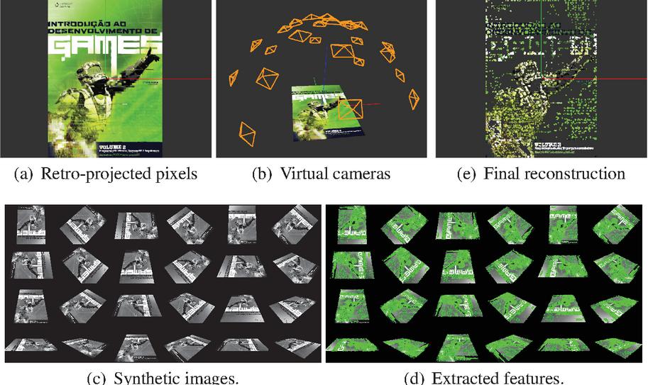
Figure 2 Object registration steps. Given a digital image and the object scale (in meters): (a) Pixels are retro-projected to 3D space; (b) 24 virtual cameras are positioned over the surface of a semi-sphere around the object in order to cover several perspectives; (c) Image viewed by each virtual camera; (d) ORB features are extracted for each image; (e) 3D points not associated with, at least, two ORB descriptors are filtered out. In this example, the input image had 1,543,500 pixels and the database received 21,418 3D points and 53,987 ORB descriptors.
4.3 Object Database Registration
We built an object database (ODB) for the object recognition task. The ODB stores 3D reconstructed points and an ORB descriptor set extracted from several images of the object with different perspectives. Object features are transformed into a Bag of Words (BoW) representation, with an inverted index and a direct index [16]. To make the registration process easier for the user, we perform a synthetic object reconstruction from only one digital image. For planar objects, like books, magazines, and photos in general, this approach is straightforward. Figure 2 shows each step of the registration method. In our experiments, we built a small database composed of 5 planar objects.
4.4 Object Mapping
Object mapping is the process that recognizes new objects in the input image, finds 3D correspondences and fuses the SLAM static map with the object point cloud. It is divided into two tasks: Recognition and Placement, which we describe below.
4.4.1 Recognition
Our object recognition algorithm was inspired by the work in [15], but with some adaptations due to the dynamic nature of our scenario and the small database we built.
Given a new key-frame already processed by Local Mapping, we query the ODB by passing the BoW representation of the entire image. This operation returns the best candidate objects presented in the image (we select the top-2). Then, we perform ORB descriptor matching between each candidate and the key-frame. We use their BoW representation to reduce the search space in a way that only pairs of features under the same node at a pre-defined level on the vocabulary tree are compared. We follow the ORB-SLAM2 that uses a similar method to support re-localization and loop detection tasks and we define this level for the second one (top-down) in a vocabulary tree of 6 levels.
If enough matches are found (empirically defined as 30), we solve a Perspective-n-Point (PnP) problem to find an object pose relative to the camera (). A RANSAC scheme [30] run the algorithm proposed by [31] until the maximum number of iterations (100) is performed or the re-projection error is less than . If the estimated pose is supported by a minimum number of inliers (20), we take an observation. When two observations for the same object is taken, its detection is confirmed and it passes to the next step.
4.4.2 Placement
In order to place the detected object in the map, we need to know its pose relative to the world frame (). A rough computation for this pose can be made by composing the known transformations and . This formula assumes that the scale, , between world and object spaces is equal to one. Therefore, we compose these rigid poses, but then we optimize the composed transformation and the scale by minimizing an alignment error function, described by Equation (6).
| (6) |
The object state is parameterized as the minimal representation of the similarity pose, . The alignment errors defined by Equation (7) are supposed to be uncorrelated and to follow a Gaussian distribution. Adopting the standard deviation of the point triangulation, , we define the covariance matrix as .
| (7) |
The function maps the state vector to the similarity matrix it represents; is the j-th pair of 3D points corresponding to the object in the world and local frames.
At this point, if the estimation was supported by enough inliers, we have a good guess for the similarity transformation between object and world frames. Then we can perform a projection-based matching to find more object points in the map. If we found at least 3 more matches, we optimize the similarity again.
Finally, we fuse the SLAM map with the object point cloud. For this operation, we take each corresponding pair and copy the meta-data with all observations of the map-point to a new one created for . The coordinates of this new map-point are computed as . Then we remove each from the SLAM map and add the map-object instance with all its map-points.
4.5 False-negatives Rejection
Our proposal is very sensitive to false-negative mismatches. Map-points that belongs to an object, but data association does not match them for any reason, will be treated as a background static point. If the object moves to another place, these points will remain stationary. Over time, this breaks the map’s consistency, causing problems in every module of the system. To address this issue, we developed a simple strategy to deal with these unmatched points. First, we take the bounding box of an object, project their vertices in the key-frame image and compute their Minimum Bounding Rectangle (MBR). Then we take the key-frame features inside the MBR and for those not matched with the object, we check if its corresponding map-points are inside the 3D bounding box. These points are erased from the map. This process runs for every key-frame.
4.6 State Machine
After an object is placed in the map, recognition is no more required for it. Therefore, back-end now updates the object visibility state. The state machine diagram is illustrated in Figure 3 and we will detail it in the following paragraphs.
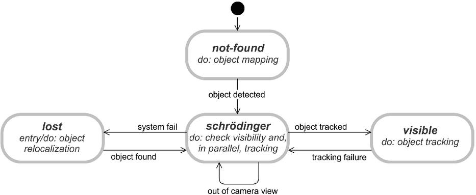
Figure 3 Object visibility state machine diagram.
From the moment an object registered in the database is defined as a target of the system by the user, it is retrieved from the database and put on the not-found state. While there are not-found objects, our system performs the object mapping process. When an object is detected, its state changes to the one named as schrödinger.
The name of this state is a reference to the famous Schrödinger’s Cat experiment [32]. Although the object has been detected, this is true for a key-frame in the back-end thread, i.e., for an instant in the past. The front-end is probably dozens of frames ahead. So we do not know if the object is visible or lost for the current frame. We will only know after “looking at what is inside the box”.
While the object is on schrödinger state, both front-end and back-end can change it. If front-end can locate the object, it is changed to visible and only a potential future failure in the tracking will lead to another state change, back to schrödinger. The back-end, in turn, will try to check if the object is not visible due to a system failure or simply because it is out of the camera field of view (Section 4.6.1). It is only possible to discriminate these two cases because the camera localization is independent of the object tracking. If the system realizes the object is out of the camera field of view, then the object remains on schrödinger state. Otherwise, there was a system failure, so the state changes to lost.
As soon as the object enters the lost state, the re-localization algorithm (Section 4.6.2) is invoked for the same key-frame that caused the transition to corroborate the visibility checking result. If the re-localization is successful then the object immediately changes back to schrödinger. Otherwise, the state is kept until the object is re-localized in some future key-frame.
While the object is on the visible state, back-end only tries to find new 3D correspondences by projection-based matching to feed the local map and support the tracking.
4.6.1 Checking object visibility
To verify if an object is not visible in front-end due a system failure or because it is out the camera field of view, we take the object’s MBR and compute the intersection area between it and the image. Then we compute the ratio between the intersection area and the whole image. A threshold of value 0.07 was empirically defined. This implies the object will be treated as out of the camera field of view if it occupies, at least, 7% of the total image area.
4.6.2 Object re-localization
Re-localization is a simplified recognition step, i.e., without querying the database and performing a PnP estimation. It starts by matching ORB descriptors of the lost object and the key-frame, following the BoW-based formulation. With enough matches, the last valid similarity is optimized for the new matches. With enough inliers, projection-based matching is performed and the 7DoF pose is optimized again.
5 Experimental Results
Object-aware SLAM works in the literature usually evaluates, in a numerical way, only the camera localization accuracy. The accuracy of the object placement or tracking is only evaluated qualitatively. To numerically evaluate the object tracking accuracy, we defined a measurement error formula (Section 5.1). Since we did not find in the literature compatible datasets to our proposal, we built a small dataset with common movements for an AR application (Section 5.2). We execute our system and take accuracy for each sequence of our dataset (Section 5.4). We also implement some AR demo apps using our system and show the visual results (Section 5.3). We close this section with a discussion about the obtained results (Section 5.5).
5.1 Cube Displacement Error (CDE)
Cube displacement error is our adaptation of the measurement proposed by [33] to evaluate calibration quality in the fiducial markers arbitrary field. For each frame, the error is defined as the average displacement of the 8 vertices of a cube projected over the object frame. In other words, let be the object pose relative to the camera , let be that ground-truth transformation and let be the set of vertices of a cube centered at the origin with side length . We define CDE for frame as shown in Equation (8).
| (8) |
We compute the root-mean-squared error (RMSE) for our CDE measurement by the Equation (9).
| (9) |
We also calculate the arithmetic mean and standard deviation for all frames in which the object was considered visible. In this way, we can indirectly evaluate the quality of the estimated rigid transformation in each frame and also the scale computed in the detection. The cube edge length is defined as the dimensions, in meters, of the fiducial marker centered in our target object (Figure 4).
Figure 4 Marker object used in our sequences. The fiducial marker in the center has side , while the entire texture has dimension 24,7 cm 17,3 cm.
5.2 Dataset
We record 6 video sequences (S1 to S6) with duration about 30 to 40 seconds per video. We captured images with a resolution of 640x480 pixels by a Microsoft LifeCam RGB camera at 30 frames per second. Each sequence provides a specific test, with different movements.
S1 We keep the marker stationary on a table and manually translate the camera over straight lines.
S2 Marker still fixed, we manually translate the camera around the marker center, rotating the camera to keep the focus at the center. The distance also changes.
S3 Here we fix the camera and manually translate the marker on the table over its x- and y-axis;
S4 Camera still fixed, we manually rotate the marker on the table around its center in a full 360-degrees;
S5 Camera fixed again, we manually do an out-plane rotation until the marker plane is almost orthogonal to the camera. Then we manually translate the marker toward the camera;
S6 Free motion. We simultaneously move both the marker and the camera freely.
We employed the ARToolKit library4 to determine the ground-truth of each sequence. ARToolkit is an open-source library5 specialized in tracking fiducial markers. Hence, we created a textured planar object6 with a fiducial marker in its center, whose defines the world origin (Figure 4).
Due the map initialization process, we synchronize our system with the ARToolKit by recording for a few seconds part of the scenario with multiple features without the marker object. Then, we move the camera until we frame the object correctly in the image and proceed with the planned test.
5.3 Augmented Reality Applications
Our proposal enables object movement throughout the map while they are visible by the camera. To demonstrate this, we implemented an AR application with one target object that we move freely through the scene. Figure 5 shows some frames of this application and the corresponding map state for that frame.

Figure 5 Moving object tracking demo: At the top, some application frames, and at the bottom, the corresponding map state.
Multiple targets are also allowed by our proposal (Figures 6(a,e) 6(b)). The computational cost of inserting more targets is proportional to the computational cost of inserting more cameras to a motion-only Bundle Adjustment. Only a 6DoF node is added in the optimization graph for each new target. The number of constraints is defined by the number of observed map-points, which is the same for each scene regardless the number of targets.
All the above applications are possible with a classical marker-based tracking system. The main advantage of using SLAM-based systems to build Augmented Reality applications is the possibility to keep the augmentation visible even when the marker object is entirely out of the camera view. This is only possible because the camera localization is independent of the object that marks the referential. In this way, we can also solve the marker total occlusion problem (Figures 6(c,e) 6(d)).
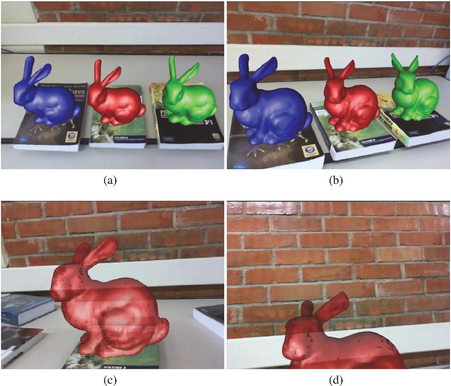
Figure 6 Demos of (a)–(b) multiple targets tracking and (c)–(d) marker total occlusion.
5.4 Object Tracking Accuracy
To evaluate the accuracy of the object positioning, we run our system 5 times for each sequence and record the object trajectory in a file. Then we compare our estimated trajectories to the one obtained by ARToolKit. We select the median RMSE among the 5 executions and expose these results in Table 1 that also shows the proportional error with reference to the cube size, the standard deviation, and the maximum error. The evolution of CDE over time is shown in Figure 7.
Table 1 Cube displacement error (cm)
| SEQ. | RMSE (%) | STD (%) | MAX |
| S1 | 1.726 (24.66) | 0.790 (11.29) | 4.529 |
| S2 | 2.769 (39.56) | 1.352 (19.31) | 9.298 |
| S3 | 1.459 (20.84) | 0.627 (08.96) | 4.917 |
| S4 | 2.407 (34.39) | 0.645 (09.21) | 9.306 |
| S5 | 2.455 (35.07) | 1.217 (17.39) | 8.112 |
| S6 | 2.224 (31.77) | 0.847 (12.10) | 4.725 |
| Proportional error relative to the cube size (7cm). | |||
Note that ARToolKit also provides just an estimation of the pose, so what we are evaluating here is how close our system is from ARToolKit. Another note is that CDE encapsulates both object tracking and camera localization errors, since the transformation is the composition of the model () and the view () matrices.
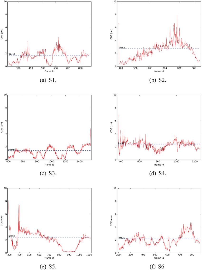
Figure 7 Evolution of the CDE error per frame on each recorded sequence.
5.5 Discussion
We can note from Table 1 that the maximum error in 3 sequences is distorted, totally misaligned with the marker. Looking at the graphs in Figure 7 we can see that these peaks occur at the first frame in which the object is visible. Thus, we can associate this result to a problem in the object mapping task, probably caused by mismatches. An evidence of this is illustrated in Figure 8.a, where we can see a slight blur effect. The same figure, on the right, shows the CDE for the subsequent frame. The error was corrected, giving us a demonstration of the feasibility of our optimization framework.
It is worth noting that the quality of the camera have high impact in CDE measurements. We believe that using a camera with a higher frame rate can mitigate this problem by reducing the motion blur effect.
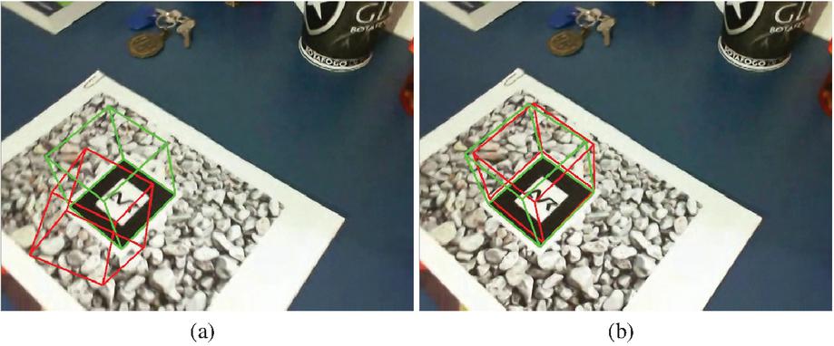
Figure 8 CDE visualization for two subsequent frames of the S2 sequence. The left frame shows a detection error (note the blur on it), it is the first frame right after the target recognition, but as we see on the right frame, the error is immediately corrected by our front-end optimization.
Graphs S2 and S5 (Figures 7(b) and 7(e), respectively) shows the effect as we distance the camera from the object. In S2, when we frame the marker, we distance the camera from it during the translation around it. The result is that error increases over time. Before the end, we approach the object again and error decreases. In S5, we have the opposite situation. We start by out-plane rotating the marker and then translating it towards the camera. This effect is probably related with ARToolKit trajectory due the well-known marker distance problem.
Graphs S3 (Figure 7c()) and S4 (Figure 7(d)) illustrate a problem we can identify by using the system. The translation movement is more challenging for our implementation than rotation. It is worth considering that the CDE captures this problem. We can note the S4 graph is more constant than S3 which has many peaks and valleys. During translations, we note that valleys appear when the movement stops, and the peaks appear during the motion. A possible reason for this issue is probably related to the projection-based matching. A translation distances object points from its expected window more than a pure rotation. Thereby, fewer matches may be found or more outliers may be introduced, degrading the accuracy of the optimization.
The demos in Section 5.3 demonstrate that our proposal not only allows new applications in AR but also increases the interaction level between the virtual and real environments. Interaction is a fundamental feature for any AR software. Virtual objects must be over the same rules that act in the real world to increase the immersion of the user. Any progress in this direction is important and our work takes a small step in that way.
6 Conclusion and Future Works
This work presented a novel graph-based approach for tracking of multiple moving objects in an object-aware SLAM map. We developed an optimization framework that can be attached to the front-end of an object-aware SLAM system to track the camera simultaneously with objects in small environments. Our proposal combines both advantages of marker- and SLAM-based tracking systems. This means the camera is tracked even in the absence of objects and, on the other hand, moving objects are tracked relative to a global frame if they are visible. In this way, we provide a single tracking system with the ability to handle movements and occlusions of the marker object. Previous works are able to deal with only one of these scenarios.
We implemented our proposal over the ORB-SLAM2 [25] open-source code. Hence, we also implemented an object recognition module to detect and place objects in the map to feed our tracking method. We demonstrated some applications in AR and discussed the visual results. We also proposed a new approach to measure the tracking accuracy and built a small dataset to do this job. The results evidence some limitations of the system, but also demonstrate the validity of our hypothesis.
Our proposal can only estimate object movement if the scene provides enough background points to support camera localization. Thus, moving objects cannot occupy most of the observed image area, otherwise, the system will assume the whole map is in motion. Other limitations are implementation-dependent and most often related to the data association. The feature-based method requires textured objects and details observation. This substantially restricts the class of objects we can track, the distance we can be from them and the speed they can move. Our solution for dealing with false-negative mismatches is simple and does not cover some situations. For instance, map-points not observed by the current key-frame. This causes tracking failures and limits long-term operation. Addressing these limitations is our main future work proposal.
Notes
1Available at github.com/raulmur/ORB_SLAM2 [Online; 17/11/2020].
2Available at github.com/dorian3d/DBoW2 [Online; 17/11/2020].
3Original code: github.com/RainerKuemmerle/g2o [Online; 17/11/2020].
4Actually, we employed artoolkitX that is the current official name of the open-source version, but for convenience, we still refer it by ARToolKit.
5Repository: github.com/artoolkitx/artoolkitx [Online; 17/11/2020].
6We used a Vuforia pattern: library.vuforia.com [Online; 17/11/2020].
References
[1] Randall C Smith and Peter Cheeseman. On the representation and estimation of spatial uncertainty. The international journal of Robotics Research, 5(4):56–68, 1986.
[2] Hugh F Durrant-Whyte. Uncertain geometry in robotics. IEEE Journal on Robotics and Automation, 4(1):23–31, 1988.
[3] José A Castellanos, José M Martínez, José Neira, and Juan D Tardós. Experiments in multisensor mobile robot localization and map building. IFAC Proceedings Volumes, 31(3):369–374, 1998.
[4] Stefan B Williams, Paul Newman, Gamini Dissanayake, and Hugh Durrant-Whyte. Autonomous underwater simultaneous localisation and map building. In Robotics and Automation, 2000. Proceedings. ICRA’00. IEEE International Conference on, volume 2, pages 1793–1798. IEEE, 2000.
[5] Jose E Guivant and Eduardo Mario Nebot. Optimization of the simultaneous localization and map-building algorithm for real-time implementation. IEEE transactions on robotics and automation, 17(3):242–257, 2001.
[6] Jong-Hyuk Kim and Salah Sukkarieh. Airborne simultaneous localisation and map building. In Robotics and Automation, 2003. Proceedings. ICRA’03. IEEE International Conference on, volume 1, pages 406–411. IEEE, 2003.
[7] Georg Klein and David Murray. Parallel tracking and mapping for small ar workspaces. In Mixed and Augmented Reality, 2007. ISMAR 2007. 6th IEEE and ACM International Symposium on, pages 225–234. IEEE, 2007.
[8] Wei Tan, Haomin Liu, Zilong Dong, Guofeng Zhang, and Hujun Bao. Robust monocular slam in dynamic environments. In Mixed and Augmented Reality (ISMAR), 2013 IEEE International Symposium on, pages 209–218. IEEE, 2013.
[9] Kiyoung Kim, Vincent Lepetit, and Woontack Woo. Real-time interactive modeling and scalable multiple object tracking for ar. Computers & Graphics, 36(8):945 – 954, 2012.
[10] Datta Ramadasan, Thierry Chateau, and Marc Chevaldonné. Dcslam: A dynamically constrained real-time slam. In Image Processing (ICIP), 2015 IEEE International Conference on, pages 1130–1134. IEEE, 2015.
[11] Hauke Strasdat, José MM Montiel, and Andrew J Davison. Visual slam: why filter? Image and Vision Computing, 30(2):65–77, 2012.
[12] Robert Oliver Castle and David W Murray. Keyframe-based recognition and localization during video-rate parallel tracking and mapping. Image and Vision Computing, 29(8):524–532, 2011.
[13] David G Lowe. Distinctive image features from scale-invariant keypoints. International journal of computer vision, 60(2):91–110, 2004.
[14] Edward Rosten and Tom Drummond. Machine learning for high-speed corner detection. In European conference on computer vision, pages 430–443. Springer, 2006.
[15] Dorian Gálvez-López, Marta Salas, Juan D Tardós, and JMM Montiel. Real-time monocular object slam. Robotics and Autonomous Systems, 75:435–449, 2016.
[16] Dorian Gálvez-López and Juan D Tardos. Bags of binary words for fast place recognition in image sequences. IEEE Transactions on Robotics, 28(5):1188–1197, 2012.
[17] Henning Tjaden, Ulrich Schwanecke, Elmar Schömer, and Daniel Cremers. A region-based gauss-newton approach to real-time monocular multiple object tracking. IEEE transactions on pattern analysis and machine intelligence, 41(8):1797–1812, 2018.
[18] Mahdi Rad and Vincent Lepetit. Bb8: A scalable, accurate, robust to partial occlusion method for predicting the 3d poses of challenging objects without using depth. In Proceedings of the IEEE International Conference on Computer Vision, pages 3828–3836, 2017.
[19] Yi Li, Gu Wang, Xiangyang Ji, Yu Xiang, and Dieter Fox. Deepim: Deep iterative matching for 6d pose estimation. In Proceedings of the European Conference on Computer Vision (ECCV), pages 683–698, 2018.
[20] Martin Rünz and Lourdes Agapito. Co-fusion: Real-time segmentation, tracking and fusion of multiple objects. In 2017 IEEE International Conference on Robotics and Automation (ICRA), pages 4471–4478. IEEE, 2017.
[21] Martin Runz, Maud Buffier, and Lourdes Agapito. Maskfusion: Real-time recognition, tracking and reconstruction of multiple moving objects. In 2018 IEEE International Symposium on Mixed and Augmented Reality (ISMAR), pages 10–20. IEEE, 2018.
[22] Michael Strecke and Jörg Stückler. Em-fusion: Dynamic object-level slam with probabilistic data association. arXiv preprint arXiv:1904.11781, 2019.
[23] Takehiro Ozawa, Yoshikatsu Nakajima, and Hideo Saito. Simultaneous 3d tracking and reconstruction of multiple moving rigid objects. In 2019 12th Asia Pacific Workshop on Mixed and Augmented Reality (APMAR), pages 1–5. IEEE, 2019.
[24] Mina Henein, Jun Zhang, Robert Mahony, and Viorela Ila. Dynamic slam: The need for speed. arXiv preprint arXiv:2002.08584, 2020.
[25] Raul Mur-Artal and Juan D Tardós. Orb-slam2: An open-source slam system for monocular, stereo, and rgb-d cameras. IEEE Transactions on Robotics, 33(5):1255–1262, 2017.
[26] Raul Mur-Artal, Jose Maria Martinez Montiel, and Juan D Tardos. Orb-slam: a versatile and accurate monocular slam system. IEEE Transactions on Robotics, 31(5):1147–1163, 2015.
[27] Rainer Kümmerle, Giorgio Grisetti, Hauke Strasdat, Kurt Konolige, and Wolfram Burgard. g2o: A general framework for graph optimization. In Robotics and Automation (ICRA), 2011 IEEE International Conference on, pages 3607–3613. IEEE, 2011.
[28] Ethan Rublee, Vincent Rabaud, Kurt Konolige, and Gary Bradski. Orb: An efficient alternative to sift or surf. In Computer Vision (ICCV), 2011 IEEE international conference on, pages 2564–2571. IEEE, 2011.
[29] Michael Calonder, Vincent Lepetit, Christoph Strecha, and Pascal Fua. Brief: Binary robust independent elementary features. In European conference on computer vision, pages 778–792. Springer, 2010.
[30] Martin A Fischler and Robert C Bolles. Random sample consensus: a paradigm for model fitting with applications to image analysis and automated cartography. In Readings in computer vision, pages 726–740. Elsevier, 1987.
[31] Vincent Lepetit, Francesc Moreno-Noguer, and Pascal Fua. Epnp: An accurate o(n) solution to the pnp problem. International Journal of Computer Vision, 81:155–166, 2008.
[32] E. Schrödinger. Die gegenwärtige situation in der quantenmechanik. Naturwissenschaften, 23(48):807–812, Nov 1935.
[33] Siltanen, Hakkarainen, and Honkamaa. Automatic marker field calibration. In Virtual Reality International Conference (VRIC2007), pages 261–267, 2007.
Biographies

Douglas Coelho Braga de Oliveira has a B.S. degree (2016) and M.S. degree (2018) in Computer Science from the Federal University of Juiz de Fora. His research interests are Computer Graphics, Virtual Reality and Computer Vision.

Rodrigo Luis de Souza da Silva is an Associate Professor in the Department of Computer Science at Federal University of Juiz de Fora. He has a B.S. in Computer Science from the Catholic University of Petropolis (1999), M.S. in Computer Science from Federal University of Rio de Janeiro (2002), Ph.D. in Civil Engineering from Federal University of Rio de Janeiro (2006) and a postdoc in Computer Science from the National Laboratory for Scientific Computing (2008). His main research interests are Augmented Reality, Virtual Reality, Scientific Visualization and Computer Graphics.
Journal of Mobile Multimedia, Vol. 17_4, 577–602.
doi: 10.13052/jmm1550-4646.1745
© 2021 River Publishers