Experimental Evaluation of UWB Transmission Waveform with Body-Shadowing in an Indoor Environment
Supakorn Suwan and Sathaporn Promwong*
School of Engineering, King Mongkut’s Institute of Technology Ladkrabang, Ladkrabang, Bangkok, 10520, Thailand
E-mail: sathaporn.pr@kmitl.ac.th
*Corresponding Author
Received 02 July 2021; Accepted 20 October 2021; Publication 22 January 2022
Abstract
Wireless radio transmission performance in a realistic environment is a significant issue for designing and evaluating in short-range transmission technologies. Human body-shadowing is a significant propagation effect in an indoor wireless communication network. This paper presents the measurement model of impulse radio transmission with human body-shadowing in an indoor environment with IEEE 802.15.4 multipath impulse parameters. The impulse radio transfer function measurement model for the human body impulse radio transfer function with frequency band cover from 3 GHz to 11 GHz. The optimum system evaluation of impulse radio transmission is due to the human body and antennas. The characteristics of impulse radio transmission loss are using decay factor, log-normal standard, clusters, and ray arrival rate. The contributions of this research can be evaluating the human body impulse radio transfer function. And the design of the wireless radio system with the body shadowing effects and ambient environments.
Keywords: UWB technology, UWB measurement, human body transfer function, short-range propagation, optimum system.
1 Introduction
Multimedia technology is widely affected in daily human life. Quality of Service (QoS) is essential to achieve good performance in wireless communication [1]. Wireless sensor network (WSN) technology is a promising and challenging topic because it can apply to a vast scale of multimedia applications [2]. Various wireless technologies were introduced to WSN, e.g., Wi-Media, Bluetooth, ZigBee, LoRa, LTE, RFID, and ultra-wideband. The ultra-wideband (UWB) technology has an advantage for providing a high data rate, inexpensive device component, and low power requirement. Due to the benefits of the UWB, which provide good QoS for WSN [3].
The UWB technology is a radio technology for use as a new scheme in wireless impulse radio systems. The initial state in UWB technology, various organizations and industries are participating in the development. Nevertheless, UWB is still not famous because the IEEE 802.15.3a standard was never achieved due to the high price of commercial products [4]. However, some organizations or companies are still urged to develop UWB technology. The current trends of UWB are mainly focused on the design and optimization of UWB circuits, including antenna, filter, oscillator. Some researches focus on realizing personal area network system (PANS), body area network system (BANS), smart device, and wireless localization [5]. The regulation of UWB is widely developed in many countries. UWB technology appears in various applications, e.g., medical service, tracking, smart home, smart office, radar imaging, surveillance, and wireless localization. At present, the IEEE standard for UWB can roughly separate into two standards, i.e., IEEE 802.15.6-2012 and IEEE 802.15.4-2020. The IEEE 802.15.6-2012 is used for BANS, and the IEEE 802.15.4-2020 is used in a low-rate wireless network. Both standards are described the general physical requirement for UWB technology [6, 7]. The characteristic of the UWB transmission is applicable for PANS that is used to interconnect between server and surrounding end-device [8]. For example, in [9], UWB measurement has been done to classify UWB propagation and transmission in small spacecraft that compare UWB and narrowband.
One of the most emerging application is the WBAN, which allow wireless communication to interact with current medical services [10, 11]. Several pieces of research on WBAN using wideband communication have been investigated. The investigation of ultra wideband body area network system (UWB-BANS) with line-of-sight (LOS) and shadowing classification by using deep learning has been studied [12]. In [13], a study of wideband propagation channels for BANS in a circular metallic indoor environment has been proposed. The propagation channel of this research is evaluated in terms of time delay. An off-body channel model is determined by Rician distribution, and stochastic Rician factor k for BANS in an indoor environment is present in [14].
Furthermore, intrabody communication (IBC) is examined using impulse radio to provide superior service of BANS with real-time communication is discussed in [15]. The evaluation and investigation of UWB-BANS with the human body model performed by different scenarios have been presented [16, 17]. In [18], the investigation of UWB impulse radio (UWB-IR) technology for BANS application using a living animal has been evaluated. Zero correlation duration (ZCD) code is introduced to improve the performance of UWB-BANS is proposed to realize the advanced design and implementation of UWB-BANS [19]. In [20], UWB technology is applied with a posture recognition method for indoor positioning. The posture recognition algorithm, least-square estimation (LSE) method, and improved Kalman filter are introduced to suppress the noise regarding distance error [21]. The indoor propagation measurement with Rake reception for improving signal quality is introduced in [22]. The indoor localization uses a wearable body sensor using UWB technology with a particle filter to reduce position error [23]. From the previous researches, the majority of the related research considers the human body effect on UWB transmission channel evaluation, including with different schemes of the evaluation model. However, there is no discussion about the optimization at the receiver part.
This paper proposes the human body shadowing channel measurement model based on the IEEE 802.15.4-2020 with multipath parameters. The UWB-IR transmission channel is measured over the FCC regulation and the IEEE standard at operating frequency at 3 GHz to 11 GHz is observed. The optimum system is introduced at the receiver part of the UWB-IR channel model as the post-processing technique to eliminate the dirty signal due to noise. The measurement results are measured and recorded by using a network equipment in the indoor environment. A time delay characteristic evaluates the results. The structure of this research include. The Section 2 will describe the IEEE 802.15.4 multipath impulse radio model. The channel measurement setup and human body shadowing multipath impulse radio model are presented in Section 3. The multipath impulse radio characteristics and model parameters are presented in Section 4. Finally, the conclusion will be discussed in Section 5.
2 IEEE 802.15.4 Standard Model
This paper models the UWB body-shadowing channel based on IEEE 802.15.4 multipath channel parameters. The transmission model uses a log-normal probability density function rather than Rayleigh probability density for the multipath gains. The UWB transmission channel with multipath components are involved with impulse response in the discrete-time domain is described as,
| (1) |
where is a clusters number, is a rays or propagation number in the clusters, is multipath gain coefficient of the ray in the clusters, is the first arrival time of the clusters, is rays delay in the clusters regarding to the first arrival time .
By elucidation, when assumed . The ray and the clusters of arrival can be derive from a Poisson process distribution given by
| (2) | ||
| (3) |
where is rate of clusters arrival and, is number of the arrival rays in each path of each clusters.
In [24], The channel modification allows rays of the clusters to fade independently, as shown in Figure 1. For example, a fading of each multipath within-clusters arrival is associated with the arrival of incoming rays. The UWB impulse radio coefficient is given by Equation (4), when the fading of clusters and ray amplitudes are in logarithm form
| (4) |
with
| (5) |
or
| (6) |
where and are independent, and is equiprobable . is mathematically described by
| (7) |
The amplitudes of each ray arrival with all clusterss are given by
| (8) |
where is the excess delay of bin and is average amplitude of the first arrival range of the first clusters.
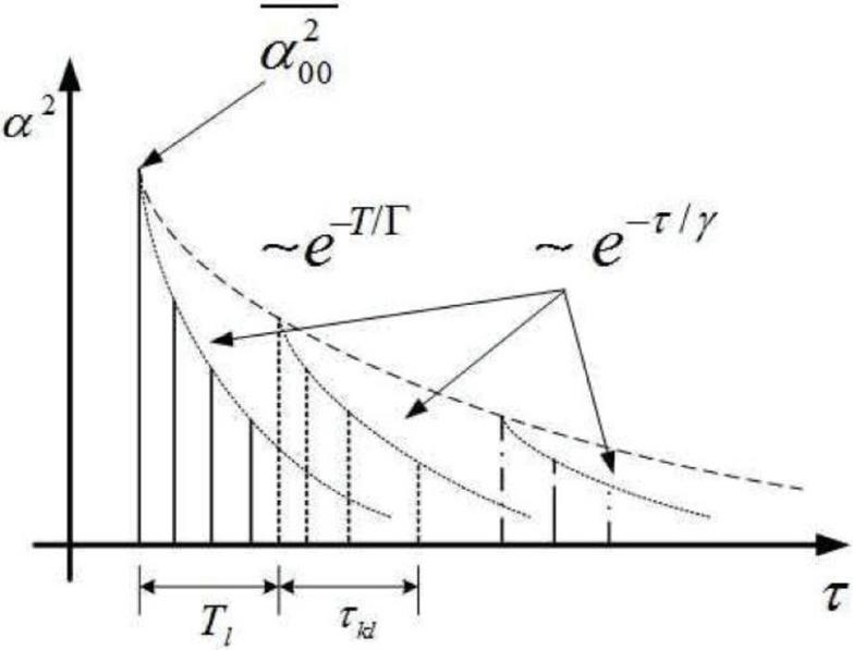
Figure 1 Characteristics of the multipath impulse radio [24].
In the previous equations, represent the fading regarding to the clusters, and associate to the fading of the rays of clusters. There are five parameters to determine the multipath channel characteristics regard to the characteristics of the UWB impulse radio, as present at Table 1.
Table 1 The determined of UWB multipath impulse radio parameters
| Parameters | Descriptions |
| Number of arrival clusters | |
| Number of arrival range in each clusters | |
| Decay factor of each clusters | |
| Decay factor of each ray | |
| The standard deviation of clusters and ray |
As shown in Table 1, parameters of match system with transmission waveform.
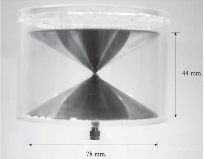
Figure 2 Human body impulse radio antenna [17].
3 Impulse Radio Measurement and Post-Processing
3.1 Measurement Equipment
In this paper, the impulse radio sounder in the domain of frequency is achieved by a vector network analyzer (VNA). The transmitted antenna (Tx) and received antenna (Rx) are connected to port one and port 2 of VNA, respectively. The experiment was done with the Tx-Rx antennas in a fixed position, including human body shadowing. A low noise amplifier compensated the loss in transmission cable. The omnidirectional propagation can be achieved by using the biconical antenna as Tx-Rx antennas to represent the UWB impulse radio’s characterization. The actual picture and the dimension of the human body impulse radio antenna are present in Figure 2. In Figure 3, an antenna transfer function characteristics are illustrated as magnitude and phase. Table 2 provides the lists of the experimental parameters.
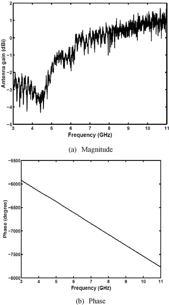
Figure 3 Human body impulse radio antenna transfer function: (a) magnitude and (b) phase [17].
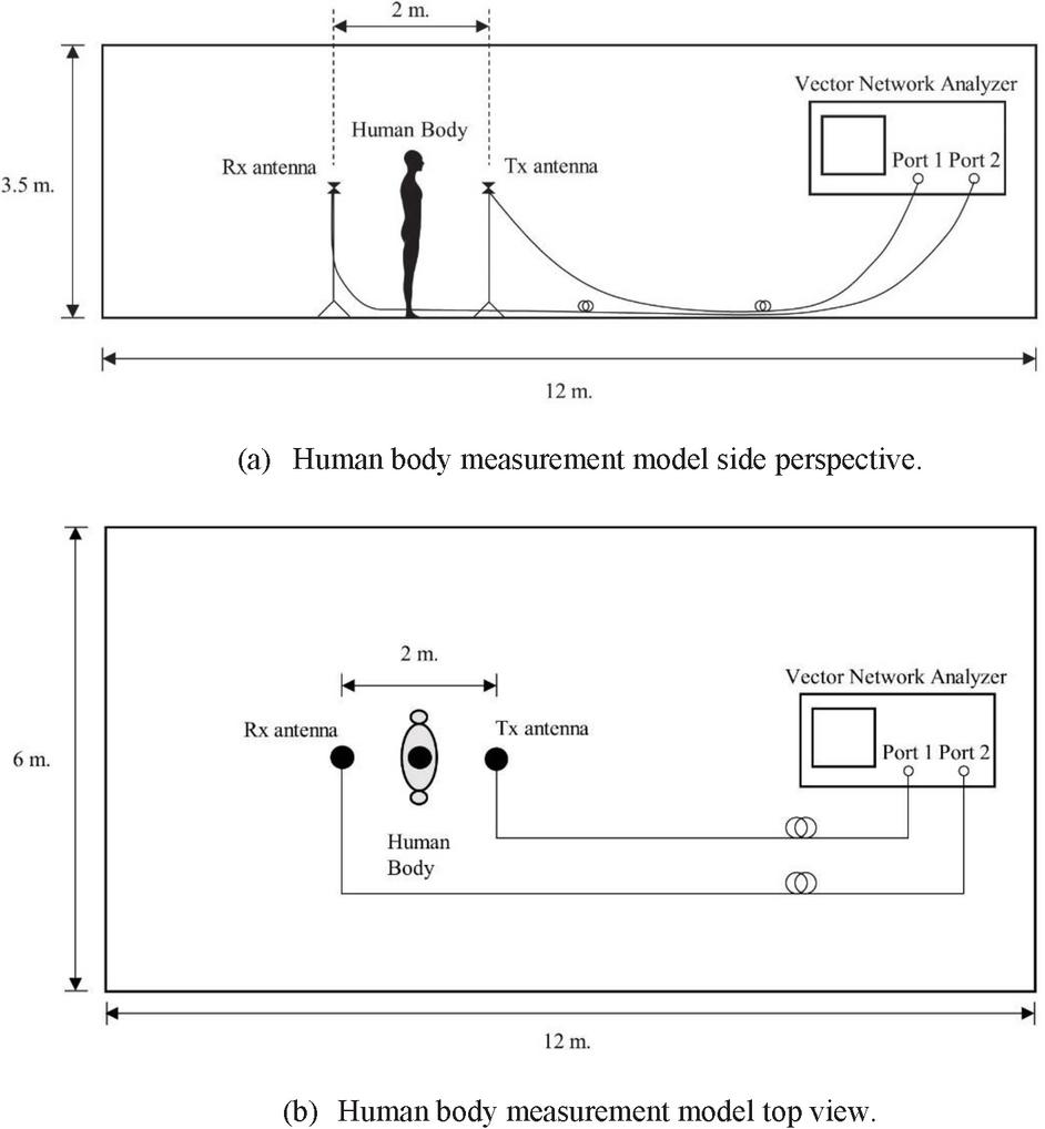
Figure 4 Experimental setup: (a) human body measurement model side perspective and (b) human body measurement model top view.
3.2 Experimental Location
In this experiment, the investigation of the shadow effect with human body in a realistic indoor model is presented. The experimental setup, including the Tx-Rx antennas and human body, are described in Figure 4. The experiment was done in a classroom 6 meters wide, 12 meters long, and 3.5 meters high. The acoustic absorption sheet is attached to a typical concrete wall. The ceiling has used a clipboard as ceiling material. The wooden door and furniture are placed inside the experiment room.
3.3 Experiment Parameters Configuration
The human body impulse radio antennas are used to measure the human body impulse radio evaluation in domain of frequency. UWB impulse radio is measured and recorded by VNA. The Tx-Rx antennas are installed at 1.5 meters from the ground with vertical polarization. The antenna is fixed, and set the separation distance to be 2 meters. The calibration at the transmission line and connector is done to increase the signal-to-noise ratio. Human body is at a fixed position between Tx-Rx antennas.
Table 2 Experimental parameters
| Parameter | Values |
| Frequency bandwidth | 3.0 GHz to 11.0 GHz |
| Frequency sweeping point | 1601 points |
| T antenna height | 1.5 m |
| R antenna height | 1.5 m |
| Polarization | Vertical |
| T-R Separation distance | 3 m |
3.4 The Optimum System
The optimum system is introduced to improve the UWB signal quality at receiver part. The general Friis’ transmission formula is applied to evaluate narrowband communication. However, the operating bandwidth is very wide. Hence, the modify of this transmission formula is presented in [25]. With the benefits of the extent of this transmission formula, the UWB transfer function can be optimized by the optimum system, including with characteristics of an input signal, free space propagation, and antenna. The steps of the optimum system are as follows.
(1) Generate the input signal by convolution the input impulse with the pulse shaping filter as described in
| (9) |
where
| (10) |
(2) Determine the UWB radio transfer function with extended Friis’ transmission formula by
| (11) |
when
| (12) |
when is a transfer function in free space, is an input transfer function, is received antenna transfer function, is transmitted antenna transfer function, is a propagation constant, is the separation between T antenna and R antenna, is operation frequency, and is a speed of light.
(3) Estimate the optimum system by determining an optimum waveform system as presented in
| (13) |
and an isotropic form of the optimum system transfer function as
| (14) |
while the condition of constant noise output power is equal to 1.
(4) Determine UWB impulse radio impulse response and optimum system impulse response by inverse fast Fourier transform (IFFT) to the UWB impulse radio transfer function and the optimum system transfer function , respectively.
(5) Calculate the output waveform corresponding to the optimum system in mathematical form by
| (15) |
and in the isotropic case is given by
| (16) |
(6) Finally, the output spectrum of the optimum system can obtain by
| (17) | ||
| (18) |
while is the isotropic form of the output spectrum of the optimum system.
4 Experimental Results and Extracted Parameters
From the time delay characteristic results, the UWB impulse radio characteristics with the multipath component can be observed by power delay profiles (PDPs) and extracted parameters.
Table 3 Time dispersion characteristics
| Parameters | Values |
| (ns) | 22 |
| (ns) | 20 |
| 11 | |
| 26 |
Table 4 The model parameters for the body-shadowing channel
| Model Parameters | Descriptions | Extracted Values |
| Number of arrival clusters | 0.08 | |
| Number of arrival range within each clusters | 3.1 | |
| Decay factor of each clusters | 19 | |
| Decay factor of each ray | 6 | |
| The standard deviation of clusters and ray | 6.6 |
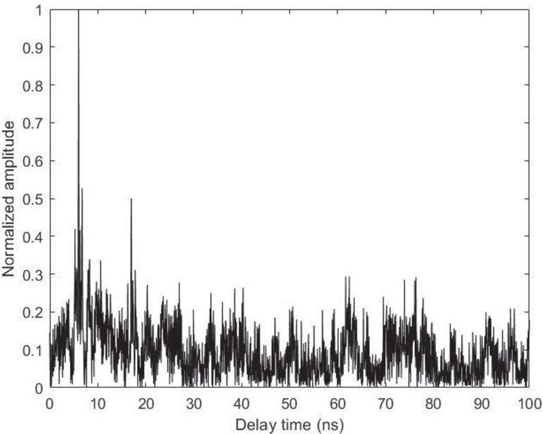
Figure 5 Delay characteristic of human body shadowing propagation.
4.1 UWB Impulse Radio Characteristics
The time dispersion of the multipath channel is an important factor that determines radio channel characteristics, including with mean exceed delay , root mean square delay spread , and number of propagation rays within 10 dB threshold. These main characteristics are extracted from the PDPs with assumed the noise level as 20 dB of peak presented in Figure 5. To obtain and , the amplitude and delay of the first arrival rays are normalized. The and are mathematically explained in [26]. The extracted time dispersion characteristics from the measurement data are illustrated in Table 3.
Table 5 The comparison of measured and model time dispersion characteristics
| Parameters | Measured | Model |
| (ns) | 22 | 22 |
| (ns) | 20 | 23 |
| 11 | 18 | |
| 26 | 60 |
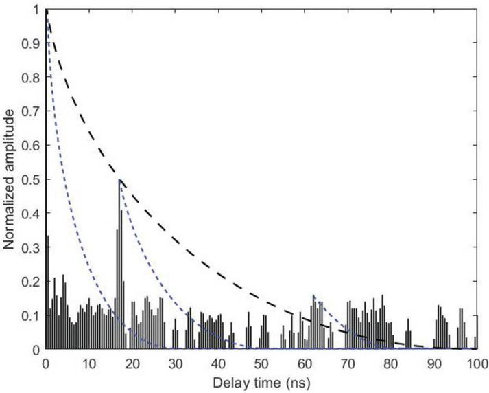
Figure 6 The normalized PDPs after post-processing with the optimum system, extracted clusters of arrival, ray of arrival and best Poisson fitting.
4.2 Impulse Radio Transmission Model Parameters
The IEEE 802.15.4 impulse radio model parameters are given by investigating the multipath propagation in the PDPs. The model is ordered to fit the measured transmission data. Figure 6 shows the normalized PDPs after post-processing with the optimum system, clusters arrival time intervals, the number of arrival ray clusters, and best Poisson fitting. This result explains with Poisson arrival assumption. The effects of multipath impulse radio transmission due to the human body, antennas, and ambient environment. Table 4 shows the parameters extracted from the measurement channel as described in Section 3. The parameters from the table can be used to generate the channel according to the body-shadowing in an indoor model, as illustrate in Figure 2. Table 5 shows the comparison of the measurement and model for the body-shadowing channel based on IEEE 802.15.4 multipath impulse radio. As shown in the table, the time dispersion characteristics of the measurement results are close to the model [20].
5 Conclusions
This paper evaluated the human body impulse radio transmission with IEEE 802.15.4 standard based on actual measurement data. The IEEE 802.15.4 standard multipath transmission waveform and time dispersion parameters are evaluated with the power delay profile with the optimum system model. The multipath impulse radio parameter results evaluation is included the clusters and ray arrival rates, decay factor, and log-normal standard deviation. The effects of multipath impulse radio transmission due to the human body, antennas, and ambient environment are shown in figures. This research merit is useful for designing and evaluating the human body impulse radio for short-range wireless communication systems.
References
[1] S. Mitra and M. A. Abu-rgheff, “Quality of Service (QoS) Issues in Multimedia Wireless Network – A Survey,” in Journal of Mobile Multimedia, vol. 5, no. 3, pp. 181–202, 2009.
[2] N. Kulkarni, D. Mantri, N. R. Prasad, and R. Prasad, “EEHRP: Energy Efficient Hybrid Routing Protocol for Wireless Sensor Networks,” in Journal of Mobile Multimedia, vol. 17, no. 1–3, pp. 245–272, 2021.
[3] J. Zhang, P. V. Orlik, Z. Sahinoglu, A. F. Molisch, and P. Kinney, “UWB Systems for Wireless Sensor Networks,” in Proceedings of the IEEE, vol. 97, no. 2, pp. 313–331, Feb. 2009.
[4] C. Abou-Rjeily, “Performance Analysis of UWB Systems over the IEEE 802.15.3a Channel Model,” in IEEE Transactions on Communications, vol. 59, no. 9, pp. 2377–2382, Sep. 2011.
[5] P. A. Catherwood and W. G. Scanlon, “Ultrawideband Communications—An Idea Whose Time has Still Yet to Come [Wireless Corner],” in IEEE Antennas and Propagation Magazine, vol. 57, no. 2, pp. 38–43, April 2015.
[6] V. Niemelä, J. Haapola, M. Hämäläinen, and J. Iinatti, “An Ultra Wideband Survey: Global Regulations and Impulse Radio Research Based on Standards,” in IEEE Communications Surveys & Tutorials, vol. 19, no. 2, pp. 874–890, Secondquarter 2017.
[7] P. S. Sharma, S. Vijay, and M. Shuka, “Ultra-Wideband Technology: Standards, Characteristics, Applications,” in Helix, vol. 10, no. 4, pp. 59–65, 2020.
[8] K. Liu, L. Cai, and X. Shen, “Exclusive-Region Based Scheduling Algorithms for UWB PANS,” in IEEE Transactions on Wireless Communications, vol. 7, no. 3, pp. 933–942, March 2008.
[9] M. Hirose and T. Kobayashi, “Experiment Evaluation of Ultra Wideband Propagation and Transmission within Small Spacecraft for Replacing Wired Interface Buses,” in International journal of communications, network and system sciences, vol. 12. pp. 59–73, 2019.
[10] C. Otto, A. Milenković, C. Sanders, and E. Jovanov, “System Architechture of A Wireless Body Area Sensor Network for Ubiquitous Health Monitoring,” in Journal of Mobile Multimedia, vol. 1, no. 4, pp. 307–326, 2006.
[11] J. Wang, T. Fujiwara, T. Kato, and D. Anzai, “Wearable ECG Based on Impulse-Radio-Type Human Body Communication,” in IEEE Transactions on Biomedical Engineering, vol. 63, no. 9, pp. 1887–1894, Sept. 2016.
[12] K. K. Cwalina, P. Rajchowski, O. Blaszkiewicz, A. Olejniczak, and J. Sadowski, “Deep Learning-Based LOS and NOLS Identification in Wireless Body Area Networks,” in Sensors, vol. 19, 4229, 2019.
[13] F. D. Cardoso, M. M. Ferreira, S. J. Ambroziak, and L. M. Correia, “A Wideband Channel Model for Body Area Networks in Circular Metallic Indoor Environments,” in IEEE Access, vol. 9, pp. 73791–73798, 2021.
[14] R. Dautov and G. R. Tsouri, “Dynamic Off-Body Rician Channel Modeling for Indoor Wireless Body Area Networks,” in IEEE Journal of Biomedical and Health Informatics, vol. 24, no. 5, pp. 1246–1254, May 2020.
[15] Z. Cai, M. Seyedi, W. Zhang, F. Rivet, and D. T. H. Lai, “Characterization of Impulse Radio Intrabody Communication System for Wireless Body Area Networks,” in Journal of medical and biological engineering, vol. 37, no. 1, pp. 74–84, 2017.
[16] S. Suwan, K. Southisombath, and S. Promwong, “A Low Power Transmission Model Based UWB Technology for BAN Applications,” 2020 6th International Conference on Engineering, Applied Sciences and Technology (ICEAST), pp. 1–4, 2020.
[17] S. Promwong, “Quantitative Evaluation of Waveform Distortion Due to Antenna in Ultra Wideband Impulse Radio,” Ph.D. dissertation, Department of Communications and Integrated Systems, Graduate School of Science and Engineering, Tokyo Institute of Technology, Tokyo, Japan, 2009.
[18] H. Liu et al., “Performance Assessment of IR-UWB Body Area Network (BAN) Based on IEEE 802.15.6 Standard,” in IEEE Antennas and Wireless Propagation Letters, vol. 15, pp. 1645–1648, 2016.
[19] D. Anzai et al., “Experimental Evaluation of Implant UWB-IR Transmission with Living Animal for Body Area Networks,” in IEEE Transactions on Microwave Theory and Techniques, vol. 62, no. 1, pp. 183–192, Jan. 2014.
[20] E. C. Kim, S. Park, J. S. Cha, and J. Y. Kim, “Improved Performance of UWB System for Wireless Body Area Networks,” in IEEE Transactions on Consumer Electronics, vol. 56, no. 3, pp. 1373–1379, Aug. 2010.
[21] X. Huang, F. Wang, J. Zhang, Z. Hu, and J. Jin, “A Posture Recognition Method Based on Indoor Positioning Technology,” in Sensors, vol. 19, 1464, 2019.
[22] K. Haneda, J. Takada, and K. Takizawa, “Evaluation of Signal Quality Improvement With Rake Reception Using an Ultrawideband Indoor Area Propagation Measurement,” in IEEE Antennas and Wireless Propagation Letters, vol. 7, pp. 337–340, 2008.
[23] T. Otim, A. Bahillo, L. E. Díez, P. Lopez-Iturri, and F. Falcone, “Towards Sub-Meter Level UWB Indoor Localization Using Body Wearable Sensors,” in IEEE Access, vol. 8, pp. 178886–178899, 2020.
[24] S. R. Saunders, and A. Aragón-Zavala, Antennas and propagation for wireless communication systems, Hoboken, NJ, USA: John Wiley & Sons, 2007.
[25] S. Promwong and J. Takada, “Free Space Link Budget Estimation Scheme for Ultra Wideband Impulse Radio with Imperfect Antennas,” in IEICE Electronics Express, vol. 1, no. 7, pp. 188–192, 2004.
[26] T. S. Rappaport, Wireless Communication Principle and Practice, Second Edition, NJ, USA: Prentice Hall PTR, 2002.
Biographies
Supakorn Suwan gradurate his B.Eng. degree in electronics engineering from the and M.Eng. degree in Biomedical Engineering, King Mongkut’s Institute of Technology Ladkrabang (KMITL). Now, he is working in a department of Electronics Engineering (Electronics Engineer) and is pursuing his doctoral degree at the faculty of engineering, KMITL. His research interests are in the wireless body area network, antenna and radio wave propagation, ultra-wideband (UWB) communications systems, biomedical devices, and electronics design. He is a member of the IEEE.
Sathaporn Promwong received his Ph.D. degree in communications and integrated systems from Tokyo Institute of Technology (TIT), Tokyo, Japan, his M.E. degree in electrical engineering, and his B.Ind.Tech. degree in electronic technology from KMITL, Bangkok, Thailand. He is a telecommunication engineering department member, Faculty of Engineering, KMITL. His research interests are in the areas of partial discharge localization, antenna and radio wave propagation, wireless energy transfer, channel measurement for wireless communications, broadcast and multimedia technology, ultra-wideband (UWB) technology, wireless localization, and wireless body area network (WBAN). He is currently an IEEE Broadcast Technology Society (BTS) Thailand chapter chair and member of IEEE, IEICE, and ECTI.
Journal of Mobile Multimedia, Vol. 18_3, 845–860.
doi: 10.13052/jmm1550-4646.18319
© 2022 River Publishers