Design and Validation of Quantum Key Management System for Construction of KREONET Quantum Cryptography Communication
Kyu-Seok Shim, Yong-hwan Kim, Ilkwon Sohn, Eunjoo Lee, Kwang-il Bae and Wonhyuk Lee*
Advanced Quantum KREONET Team, KREONET Center, Div. of Science and Technology Digital Convergence, Korea Institute of Science and Technology Information, Daejon, Korea
E-mail: kusuk007@kisti.re.kr; yh.kim086@kisti.re.kr; d2estiny@kisti.re.kr; saranha@kisti.re.kr; kibae@kisti.re.kr; livezone@kisti.re.kr
*Corresponding Author
Received 15 September 2021; Accepted 08 March 2022; Publication 23 July 2022
Abstract
As it has been recently proven that the public key-based RSA algorithms that are currently used in encryption can be unlocked by Shor’s algorithm of quantum computers in a short time, conventional security systems are facing new threats, and accordingly, studies have been actively conducted on new security systems. They are classified into two typical methods: Post Quantum Cryptography (PQC) and Quantum Key Distribution (QKD). PQC aims to design conventional cryptography systems in a more robust way so that they will not be decrypted by a quantum computer in a short time whereas QKD aims to make data tapping and interception physically impossible by using quantum mechanical characteristics. In this paper, we design a quantum key management system, which is most crucial for constructing a QKD network and analyze the design requirements to apply them to Korea Research Environment Open NETwork (KREONET). The quantum key management system not only manages the lifecycle, such as storage, management, derivation, allocation, and deletion of the symmetric key generated in QKD but also enables many-to-many communication in QKD communication based on the key relay function and P2P communication to overcome the limitation of distance, which is a disadvantage of QKD. We have validated the designed quantum key management system through simulations to supplement the parts that were not considered during the initial design.
Keywords: Quantum cryptography communication, key management system, KREONET, post quantum cryptography, IPsec.
1 Introduction
Recently, with the advancement and development of quantum computing, conventional security systems have faced new threats, and accordingly, studies on new security systems have been actively conducted. This is because it has been proven that the RSA encryption method, a conventional security system, can be unlocked quickly by using Shor’s algorithm, while it takes hundreds of years to break in conventional computing systems [1, 2]. Studies on new security systems such as Post Quantum Cryptography (PQC) and Quantum Key Distribution (QKD) are underway in various fields, and among them, QKD is a technology that uses the quantum mechanical characteristics of photons to generate a symmetric encryption key through 1:1 communication in the Qubit unit based on a single photon and uses the generated encryption key to send/receive encrypted data [3]. In QKD, a single photon has quantum mechanical characteristics such as non-replicability and collapse after measurement. Thus, even if an intruder attempts eavesdropping, it can detect the eavesdropping, and it is known as a secure protocol.
In QKD system, since only point-to-point (P2P) key distribution is allowed, a quantum key management system (QKMS) must be constructed for key distribution at the network level. Because Korea Research Environment Open NETwork (KREONET) supports a nationwide high-performance network infrastructure, it must facilitate not only P2P short-range key distribution but also many-to-many long-range key distribution [5]. If the network is constructed with QKD only, it will require a significant amount of cost. Therefore, a QKMS is required, which can manage generated quantum keys and manage the key life cycle such as allocation and deletion. Furthermore, since the QKMS may be different depending on the supplier of the QKD system, quantum key management and operating system that can manage heterogeneous systems in a single system is required.
Because QKD systems facilitate only P2P key distribution, the goal of QKMS design is to expand the users of generated quantum encryption keys, increase quantum encryption key-applied services, and build a nationwide quantum cryptography communication network. Since a QKMS is required for key distribution at the network level, and the QKMS is different depending on the supplier of the QKD system, an operating system that can integrate and manage them. Furthermore, for the integrated management of data transmission security in the national research network construction project, it is required to establish a design strategy to derive the most suitable key management system design method comprehensively after broadly reviewing the current QKD development trends and the encryption trends of the key management layer. Finally, in terms of constructing the backbone lines of KREONET and providing services between research-supporting lines, it is required to conduct studies on comprehensive key management systems to build a QKD system environment and provide the quantum cryptography communication network’s services.
Therefore, this paper discusses the designing of QKMS that can solve the problem of P2P communication, a short-range communication, which is a drawback of the QKD system; that can be applied to KREONET, which has a star-type network topology; that can maximally increase the utilization rate of quantum keys.
In this paper, following the introduction of this section, Section 2 provides a simple introduction of quantum cryptography communication and KREONET and discusses the current South Korean and international research status on quantum cryptography communication by reviewing related studies. Section 3 proposes a QKD network architecture suitable for KREONET, and Section 4 proposes a method of designing QKMS in the KREONET QKD network architecture. Section 5 validates the QKMS design, and finally, Section 6 ends this paper with the conclusion and description of future studies.
2 Related Work
This section mentions studies related to QKMS designs. First, we analyze quantum cryptography communication and QKMS to derive requirements and mention KREONET, to which the QKMS will be applied. Finally, we investigate the current South Korean and international research status on QKMS for quantum cryptography communication.
Research on quantum cryptography communication has been actively conducted ever since it was proved that using Shor and Grover algorithms, quantum computers can easily break into conventional security systems. Although quantum computers have not been developed yet, it is necessary to construct quantum cryptography communication as a countermeasure to storing encrypted data at the present and deciphering them when quantum computers are developed in the future.
Quantum cryptography communication technology is a method that ensures security by the law of quantum mechanics, replacing conventional security methods on communication. Because physical eavesdropping and interception are impossible, and even if they are attempted, the value of Quantum Bit Error Rate (QBER) increases, the corresponding Qubit is not used. Therefore, it has been theoretically proven that eavesdropping or interception is impossible in quantum cryptography communication.
However, quantum cryptography communication has several limitations. First, N2N communication is impossible. Because it has a structure of generating a symmetric key through a QKD device linked with a quantum channel, only 1:1 communication is possible. Second, the communication distance is limited. A single photon is sent through a quantum channel, and the QKD device that generates symmetric keys has a limitation of 80–200 km. Therefore, it is difficult to apply to a nationwide KREONET.
QKMS is a device that can resolve this disadvantage. It can provide the generated quantum encrypted symmetric keys to many users and various services based on P2P communication, and the limitation of the communication range can be solved using the key relay function of the QKMS. Because KREONET has local networks throughout the nation, and each local network is connected to various organizations and users, it is very expensive to connect each section with QKD devices. Therefore, QKMS is a very crucially required element, and an efficient quantum cryptography communication network can be constructed depending on the design of QKMS.
Various countries are conducting research on establishing quantum cryptographic communication. There are DARPA in the U.S. [10–12], SECOQC in Europe [13, 14], and establishment of Beijing-Shanghai backbone quantum cryptography network in China [15–25]. TokyoQKD of Japan is a prime example of QKMS construction in quantum cryptography communication construction [4]. In TokyoQKD, a centralized management network was constructed using the Key Management Server (KMS). As shown in the Figure 1 below, TokyoQKD consists of six nodes, and the quantum cryptography communication network has a maximum range of 90 km. In its structure, each link generates a secret key using an independent method; the generated secret key is moved to the Key Management Layer (KML); the secret key is received through a Key Management Agent (KMA). Since KMS is installed in Koganei-1, Koganei-2, Otemachi-1, and Otemachi-2, and KMA is installed in every node, the centralized management of the quantum cryptography communication network is facilitated.
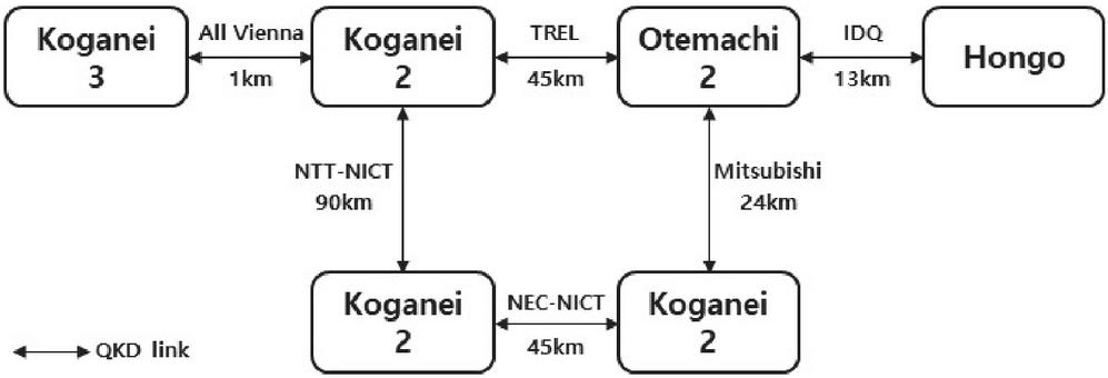
Figure 1 Network structure of TokyoQKD.
KREONET is a national research and development (R&D) network managed and operated by the Korea Institute of Science and Technology Information [6, 7]. It supports high-performance network infrastructure to provide research resources such as various science and technology information resources, super-computing, GRID, e-Science applications to about 200 major R&D organizations including companies, universities, and research institutes. Based on this, it provides South Korean researchers with a joint and collaborative research environment for advanced application research activities, thus playing an important infrastructure role as a national research network.
In this paper, we propose the design and validation of a QKMS to build and support a quantum cryptography communication network for the infrastructures and services that require a high level of security in KREONET.
3 QKD Network Structure Suitable for KREONET
In this section, we propose a connection structure and interoperation interface for generating, managing, and supplying quantum encryption keys; a structure and a key relay method for accommodating heterogeneous QKD. Layers are divided by functions to accommodate heterogenous QKD and facilitate key relays, and the structure is designed in a way of logically dividing QKD objects and QKMS. The management interface is defined additionally for the QKD network composition and management and the equipment management.
3.1 Network Structure and Interface
First, we propose an interface and linking structure design between QKD-QKMS-transmission and exchange equipment. In the QKMS of the Quantum Key Distribution Network (QKDN), the quantum layer and the transport layer are divided: the former is for key exchange and management for key generation and relay and the latter is for composing data channels using encryption keys. As shown in Figure 2, the quantum layer is a layer that performs key exchange/management/supply, and internally, it is divided into the Key Supply Agent (KSA) and Key Management Agent (KMA) of QKMS for key management/supply and the QKD for key exchange. The transport layer constructs a data channel by receiving encryption and decryption keys from the KSA of QKMS. Here, the interfaces required for key generation/management/supply in QKMS are divided into three types. The first one is an interface between KMA and KMA, which is an interface for key synchronization and key relay. The second one is an interface between KSA and SAE (transmission equipment), which is for supplying encryption and decryption keys. The last one is a QKD-KMA interface, which is monitoring and controlling the QKD status and relaying key streams.

Figure 2 Components and interfaces of quantum layer and transport layer.
The functions required for the effective management of QKD nodes and KM domains should be designed by dividing them into layers. In this paper, we classify the QKDN layers and define the role of each layer. The layers of QKDN are divided into four layers: network management layer, equipment management layer, QKD layer, and transport layer. The network management layer performs the role of configuring and managing the QKD network, and the equipment management layer performs the role of managing configuration, performance, and failure of the managed equipment and managing KM. The QKD layer performs the key stream generation and key distribution between QEs, key management, key use policy application, and supplying NE with keys used for encrypting and decrypting data channels. Lastly, the transport layer performs the role of generating and managing data channels for transmitting encrypted data between domains.
QKMS has components in each layer and performs the QKMS functions of each layer. First, the network management layer configures the Network Management System (NMS) and performs the role of configuring and managing QKD/transmission network. The equipment management layer configures the T-EMS and Q-EMS, and the T-EMS performs the role of setting and controlling data channels. Q-EMS performs the QKD equipment (QKDE) management for setting and controlling QKD modules and QKD channels; sets QoS and key management policies for key consumers and performs QoS policy-based session management for multiple key-consumers; performs routing control for key relay; performs key policy management for setting and controlling KM channels. The QKD layer manages the QKDE that generates and synchronizes key streams between QEs; receives and manages the key stream generated by the QKDE; supplies the keys to KMA and SAE that manages and stores the key life cycle so that they can be used for encryption and decryption. Lastly, there is KRA that performs the role of key relay for mid/long-distance quantum cryptography communication.
In addition to the basic configuration, the design for the heterogeneous quantum key management structure should be considered in KREONET. KREONET has local networks throughout the nation and connects each local network to construct the backbone network. If a heterogeneous quantum key management structure is not designed, only the same type of QKD equipment and QKMS equipment has to be adopted, and the QKD protocol must be unified. Furthermore, from the aspect of scalability, it is imperative to design a heterogeneous quantum key management structure for expansion with a variety of QKD equipment and a variety of QKD protocols.
The key management object and the QKD object must be separated to accommodate the heterogeneous quantum key protocols. In this design, we have selected a structure that logically separates QKDE and QKMS in the QE system and designed a structure that allows the interoperation with various QKD modules in the QKMS. The block design of QKMS facilitates the easy addition of various versions and new protocols without changing the main frame. The block design is discussed in detail in Section 4. Design of KREONET QKMS.
For the construction of a nationwide quantum cryptography communication network, we need to design interfaces for connecting each layer and equipment. We define interfaces between NE (transmission equipment), which is a part of components, QKMS’s KMA, KSA, KRA, QKD, and KMA, and neighbor KMAs. Furthermore, we define an additional interface for linking the management system and equipment with the goal of managing QKD and KM. The Figure 3 illustrates the relationships and interfaces between components, and the definition of each interface is as follows.
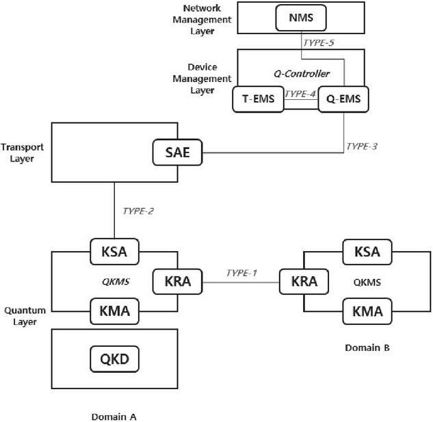
Figure 3 Interoperation interfaces of QKMS structure.
Type-1 interface is an interface between KMA and its neighbor KMA, which is an interface for key synchronization and key relay. Type-2 interface is an interface between KSA and transmission equipment, which is an interface for supplying keys required for encryption and decryption. Type-3 interface is an interface between Q-controller’s Q-EMS and QKD equipment, which is an interface for requesting key generation between domains, delivering transmission equipment authentication information, delivering key relay path, and reporting key generation status. Type-4 interface is an interface between T-EMS and Q-EMS, which is an interface for requesting key generation between domains, delivering transmission equipment authentication information, and requesting public channel configuration. Type-5 interface is an interface between NMS and Q-EMS, which is an interface for delivering network configuration information. Lastly, the interface between QKDE and KMA is an interface for monitoring and controlling the QKDE status and delivering key streams.
3.2 Quantum Key Management and Transport Structure and Procedure
To provide the quantum cryptography communication network services. The QKMS in each domain manages a separate quantum key pool for every QKMS, respectively, on the network. Furthermore, to provide a service between arbitrary terminal nodes, it manages the service key pool of the corresponding terminal node. On the other hand, the quantum key pools can be classified mainly into quantum keys of the direct method, which are obtained through physical connection with QKD equipment, and quantum keys of the indirect method, which are generated through trusted node-based quantum key delivery without physical QKD equipment connection.
Hence, it is imperative to design a key relay structure to construct the KREONET-based quantum cryptography communication network. Since there is a limit in the distance due to the characteristics of quantum cryptography communication, a key relay structure should be designed for smooth quantum cryptography communication nationwide and future quantum cryptography communication between nations. Under the premise that the trusted nodes are protected from external attacks in the key relay structure, the key relay is performed in the procedure shown in Figure 4. First, T-EMS sends the Domain ID pair required by the key to Q-EMS, and Q-EMS sends the transport path information to the pertinent Master KRA (A), Relay KRA (B&C), and Slave KRA (D). If Q-EMS sends a key stream generation request to A and D, A uses a random number generator (QRNG) to generate a key stream. The generated key stream is delivered to D through a key relay process, and the key relay process is as follows: when A sends a key relay request to B, the key pair information and key data are transmitted in a key stream between A and B by encrypting them with XOR operation. If the next process is performed between B and C and between C and D, then A and D can divide and have the quantum cryptography symmetric key.

Figure 4 Key relay structure.
On the other hand, currently, it is impossible to generate a sufficient amount of quantum keys to provide stable quantum cryptography communication network services based on the QKD technology, and there is a lack of relevant policies for quantum key management. Therefore, this paper proposes a derived key-based quantum key expansion scheme to resolve the constraints of services caused by the quantum key scarcity problem, which is caused by the increase in quantum key consumption relative to the quantum key generation rate and the ceased quantum key generation due to QKD layer failures.
The quantum key pool of QKMS in each domain and different arbitrary QKMS is defined as , and the total number of quantum keys in the corresponding pool is defined as . Its minimum threshold () is assumed to be already defined in advance. Furthermore, the service pool for the -th service session between arbitrary QKMS and QKMS is defined as . The Figure 5 shows examples of pools for the key management of the quantum cryptography communication network. Here, the number of quantum keys possessed is the same between each QKD domain. For example, the number of keys in of QKMS#1 is identical to the number of keys in of QKMS#3.
Because of this, the derived key-based quantum key expansion procedures for (1) quantum keys of the direct scheme and (2) quantum keys of the indirect scheme are as follows.
• (1) An arbitrary quantum key pool is detected
• (2) A new quantum key set is generated from QRNG of QKMS [8]. The number of quantum keys that can be generated is limited to a range that can be transported based on procedure (4).
• (3) Generate a derived key by selecting one quantum key () remaining in . In the case of HKDF [9], the derived key can be generated in a size of 8,000 bytes.
• (4) The new quantum key set generated through the process of (2) is OTP-encrypted with the derived key of (3) and sent to QKMS . After receiving it, QKMS decrypts it to acquire the new quantum key set.
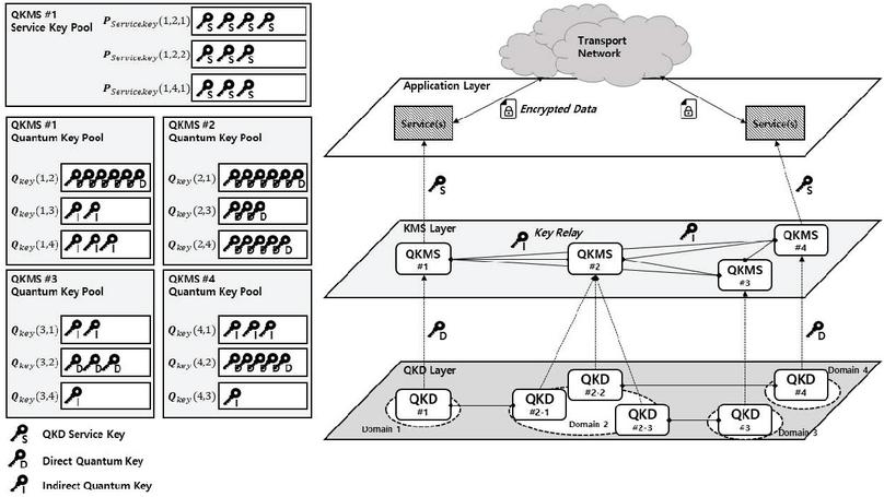
Figure 5 Quantum key management and transport structure of QKMS.
In the case of the direct scheme, since QKMS is adjacent, the procedure is terminated. In the case of the indirect scheme, procedures (3)–(4) are performed for every QKMS pair on the path of transporting quantum keys to QKMS , thereby transporting the received new quantum key set to the final destination, QKMS . Here, a synchronization procedure between QKMS and QKMS is needed to deliver ID and hash-related information.
Furthermore, the derived key-based quantum key expansion can be performed when providing an encryption service key in response to a quantum cryptography communication network service request. A derived key is generated by selecting a quantum key from the corresponding to provide the encryption key required in the service. Moreover, here, because the size of the encryption key required in each service may be different, the quantum keys stored in are generated in the same size. For , however, derived keys are generated in the key size that satisfies the service request.
On the other hand, the identifiers of the quantum key and service key generated as a derived key type are generated in a UUID format with the same rule based on the data of the key generated from each QKMS and the identifier of the corresponding QKMS pair so that the corresponding QKMS pair will have the same identifier.
4 Design of KREONET QKMS
In this section, we define the major functions of QKMS and design a structure that meets the requirements of the major standards and this work to perform the functions. To perform the functions of QKMS, the interactions between the components must be performed procedurally, and these operation procedures are a part of the main contents of this section. When designing the structure of the individual systems of QKMS and Q-EMS, we considered the scalability of functions. Furthermore, we established an appropriate design strategy for KREONET through step-by-step function design and validation.
4.1 Detailed Structure Design of QKMS Linked with KREONET Infrastructure
We have defined all components of quantum cryptography communication to design the structure of QKMS and defined its associated interfaces. The quantum cryptography communication network (QKDN) is configured in four layers, and the components of each layer are classified into network management layer, equipment management layer, QKD layer, and transport layer, as mentioned in Section 3.
The interoperation between the components of QKMS requires communication with each other and the construction of channels for such communication. The quantum cryptography communication network consists of 6 channels: quantum channel, public channel, data channel, KM channel, SAE channel, and management channel [27]. The quantum channel is a quantum optical channel between QKD modules used for distributing quantum cryptography keys [27]. The public channel is a channel for quantum cryptography protocols, QKDN control, and key management and transport protocols for generating quantum keys in quantum signals shared between QKD nodes [28]. The data channel refers to a channel for transporting data in conventional networks and is a channel that delivers data encrypted with quantum keys. The KM channel is a communication channel for key synchronization and key relay between KMAs [29]. The SAE channel refers to a communication channel for sharing Key-ID information between transmission equipment. Finally, the management channel refers to a communication channel for management between Q-EMS and KMS and between T-EMS and transmission equipment [29].
Furthermore, for connection between the components, we need the definitions of not only the channels but also the interface methods for interoperation. The interfaces for interoperation have been defined in Section 3. The method for each interface is defined as follows. Type-1 interface is an interface for performing functions between KMAs, such as key relay and KMA key synchronization. When transferring important information between domains, it transmits data by applying a data protection algorithm of high security strength that uses OTP. The following Table 1 defines the Type-1 method.
Table 1 Type-1 method
| MID | Method | Definition |
| M101 | postRelayKey (Required) | Key relay request from a KMA to a neighbor KMA |
| M102 | postValidateKey (Required) | Synchronization is performed for the key that has reformatted the key stream received from QKD between neighbor KMAs |
Table 2 Type-2 method
| MID | Method | Definition |
| M201 | getKey (Requried) | Transmission equipment sends a key request to KSA. (Key: Slave SAE ID) |
| M202 | getKeyWithId (Required) | Transmission equipment sends a key request to KSA. (Key: Key-ID) |
| M203 | getStatus (Required) | Transmission equipment inquires KMS whether there is a usable key. (Key: Slave SAE ID) |
Type-2 interface is an interface for receiving a key at SAE (transmission equipment) with KSA, and the procedure for supplying a key is as follows. When the Master SAE sends a key request to KSA, the required key is supplied using Slave SAE-ID, and then the Key-ID of the supplied key is delivered to Slave SAE. Slave SAE sends a key request to KSA using the Key-ID received from Master to receive the same key as Master SAE. The Table 2 shows the list of methods for performing these functions. The Figure 6 shows the location of message using the Type-1 method and Type-2 method.
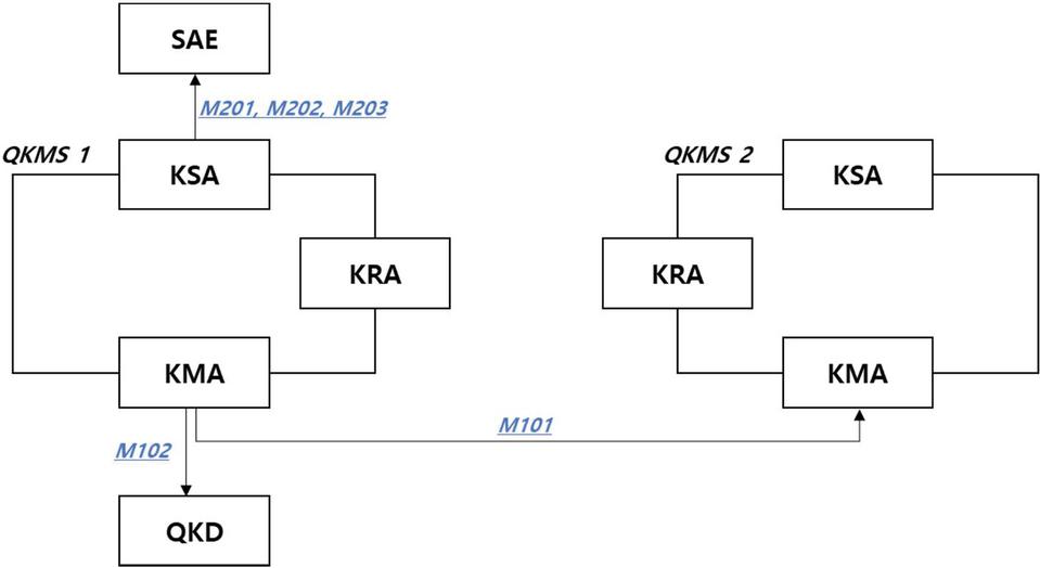
Figure 6 Component of method message.
Table 3 Type-3 method
| MID | Method | Definition |
| M301 | putDeviceInfo (Required) | Q-EMS QE: sends NE device information |
| M302 | postDeviceInfo (Required) | Q-EMS QE: updates NE device information |
| M303 | delete DeviceInfo (Required) | Q-EMS QE: deletes NE device information |
| M304 | getDeviceInfo (Required) | Q-EMS QE: queries NE device information |
| M305 | postGenerateKey (Required) | Q-EMS QE: Requests key generation |
| M306 | postRelayKey (Required) | Q-EMS QE: Requests key relay |
| M307 | postKeyPolicy (Required) | Q-EMS QE: Delivers key management policy |
| M308 | postKeyStatus (Required) | QE Q-EMS: Reports key generation status |
| M309 | postStatistics (Required) | QE Q-EMS: delivers statistical information |
| M310 | postEvent (Required) | QE Q-EMS: delivers an event such as fault, alarm, and operation information |
| M311 | postStatisticsMgmt (Required) | Q-EMS QE: sets the statistical items, generation cycle, and reporting cycle of M309 |
| M312 | postInitQkd (Required) | Q-EMS QE: Initializes QKD modules |
| M313 | postInform (Required) | QE Q-EMS: Delivers QKMS and QKDE module configurations |
Type-3 interface is an interface connected between QE and Q-EMS. This interface performs the role of requesting key generation between domains, delivering the NE authentication information, delivering the key relay path, and reporting the key generation status. The interfaces for both directions must be considered, and as shown in Table 3, M301–307, M311, and M312 are interfaces for transmitting commands for NE equipment, commands for key management, and control commands from Q-EMS to QE. M308–310 and M313 are interfaces related requests from QE to Q-EMS.
Table 4 Type-4 method
| MID | Method | Definition |
| M401 | putDeviceInfo (Required) | T-EMS Q-EMS: sends NE device information |
| M402 | postDeviceInfo (Required) | T-EMS Q-EMS: updates NE device information |
| M403 | delete DeviceInfo (Required) | T-EMS Q-EMS: deletes NE device information |
| M404 | getDeviceInfo (Required) | T-EMS Q-EMS: queries NE device information |
| M405 | postGenerateKey (Required) | T-EMS Q-EMS: requests key generation |
| M406 | postKeyStatus (Required) | Q-EMS T-EMS: reports key generation status |
| M407 | postNotifyFault (Required) | T-EMS Q-EMS: delivers NE fault information |
| M408 | postNotifyFault (Required) | Q-EMS T-EMS: delivers QE fault information |
| M409 | postPublicChannel (Optional) | Q-EMS T-EMS: requests configuration of public channel for communication between QKDEs and between KMAs |
| M410 | deletPublicChannel (Optional) | Q-EMS T-EMS: requests deletion of public channel |
| M411 | postCapabilites (Required) | T-EMS Q-EMS: exchanges the supported method list |
Type-4 interface is an interface connected between T-EMS and Q-EMS. This interface performs the roles of requesting key generation between domains, delivering transmission equipment authentication information, and requesting public channel configuration. It mainly performs the role of configuring the public channel by delivering the quantum channel information to the transmission equipment layer. Type-5 interface is an interface connected between NMS and Q-EMS, and this interface delivers the network configuration information
Table 5 Type-5 method
| MID | Method | Definition |
| M501 | putQkdtopology (Required) | NMS Q-EMS: delivers QKDN configuration information |
| M502 | postKeepAlive (Required) | NMS Q-EMS: checks the status of Q-EM |
Finally, for the QKDE-KMA interface, an interface is required for receiving the key stream exchanged between QKDE at KMA. This interface is currently in the initial stage of standardization, and only the meta-information for QKD key stream delivery has been defined. In our design, QKD-Key file was defined as shown in Figure 7. The process of delivering a key stream from QKDE to KMA is as follows. A QKD-Key file is created at QKDE. QKDE sends the QKD-Key file using a security protocol such as sftp to a specific directory of QKMS (QKMS-KMA setting). QKMS-KMA extracts the key stream by reading the file periodically.
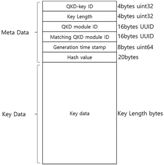
Figure 7 QKD-Key-file structure.
After defining the interfaces, this paper defines the essential functions in designing the QKMS and designs the operating methods of the functions. As shown in the Table 6 below, 12 essential functions of QKMS were selected, and for the pertinent functions, the standard document was referenced. Among the essential functions, F101–F104 are functions for configuration, and F201–F205 are functions related to operations. F301 is a performance-related function, and F302 is a fault management-related function. Lastly, F401 is defined as a security-related function.
Table 6 Essential functions of QKMS
| FID | Function | Description |
| F101 | Device registration/ change/deletion/query | A function that registers, changes, deletes, and queries the information of devices subject to interoperation between devices |
| F102 | Bootstrap | As a procedure for preparing QKMS service, QE registers its information (QKMS and QKD connection relationship, etc.) in Q-EMS, and Q-EMS sets key management policies, operation policies, etc. |
| F103 | Configuration information setting/ query | Performs SET/GET of major settings |
| F104 | Capability exchange | Exchanges supported functions between Q-EMS and T-EMS |
| F201 | Master key generation | Generates a Master Key between domains |
| F202 | Session key supply | Supplies the keys required for configuring the data channel between domains |
| F203 | Key life cycle management | Manages the key status |
| F204 | Master key pool | Stores/discards master keys |
| F205 | Key usage status report | NE reports the key usage status |
| F301 | Statistical information report | Performs reporting according to the QE’s statistical information items, collection cycle, reporting cycle, policy settings, and policies |
| F302 | Event generation and action | Generates QE’s event (Alarm, Fault, Run) and performs an action according to the event |
| F401 | Access control | When an interoperation request for a device is made, it identifies whether the device is an authenticated device and checks the rights |
F101 is a function for registering, changing, deleting, and querying devices. QKD receives the device information from Q-EMS, and QKD delivers the information to the authentication management block through the interface. As a result, the device is reflected in the device information table in QKD DB. For the pertinent request, the result is returned, and the result of registering/changing/deleting/querying the device is delivered to Q-EMS, thereby finishing the pertinent procedure. F102 is a bootstrap function. In this function, as a procedure for preparing the QKMS service, QE registers its information (QKMS and QKD connection relationship, etc.) in Q-EMS, and Q-EMS sets the key management policies, operation policies, etc. F103 is a function for setting and querying the configuration information. Using the function for performing SET/GET, which is a major setting, Q-EMS delivers the transmission equipment information to QKD, and QKD registers the information in QKD through the interface. F104 is a capability exchange function, which is a function that exchanges supported functions between Q-EMS and T-EMS. If an operator sets T-EMS to interoperate with Q-EMS, then T-EMS delivers its capability to Q-EMS. Q-EMS that has received the capability of T-EMS also delivers its capability to T-EMS.
F201 is a function for master key generation, which is a function that generates a master key between domains. When it generates a master key, the procedure can be divided into the direct mode and the relay mode. The direct mode is a procedure for generating a symmetric key at QKD in normal circumstances, and the relay mode is a procedure for generating a required key when performing a key relay for long-distance communication. In the direct mode, the key generation request is received through KMA, and the KMA requests QKDE to generate a key. In the relay mode, a key generation request is received through KMA, as in the direct mode, but the key generation is requested to QRNG, not QKDE. F202 is a function that supplies a session key. It supplies a key required for the configuration of a data channel between domains. The session key request is received through KSA from a transmission device, and the Key Manager supplies a session key according to the request conditions of the transmission device. F203, F204, and F205 are key life cycle management functions. They perform the roles of deleting and updating the used keys and allocating keys.
F301 is a function for reporting statistical information according to the QE’s statistical information items, a collection cycle, reporting cycle, policy settings, and policies. Using this function, the user can check the statistical information of QKMS and QKD. F302 is a function for event generation and action. It generates QE’s events (alarm, fault, run) and produces and performs an appropriate action according to the event. Lastly, F401 is an access control function. When a device interoperation is requested, it identifies whether the device has been authenticated and check the rights. Based on this, only the authenticated devices can be interlinked.
4.2 Deriving Detailed Design of Integrated QKMS for Application to Test Network
In this section, we construct a test network using KREONET and derive a detailed design of the integrated QKMS to apply it to the test network. The design direction is considered for the implementation in an actual network, and the QKMS functions are designed in detail. Furthermore, performance indices are derived for the performance evaluation of the QKMS to validate the designs. The Table 7 summarizes the design direction of the integrated QKMS for application to the test network. The items are the factors required when QKMS is installed, including compatibility with heterogeneous devices, scalability and high availability, convenience of interoperation, security, ease of version management, and administrator environment.
Table 7 Factors considered in designing the integrated QKMS
| Item | Description |
| Compatibility with heterogeneous devices | Separation of key management layer and QKD layer. Direction for easy interoperation with heterogeneous NE (SAE) and QKD devices (Constructs a device ID system that can accommodate heterogenous vendor device IDs, using a standardized interface is used) |
| Scalability and high availability | Scalability of individual systems based on the layer structure according to the domain and work, and high availability through this |
| Convenience of interoperation | Uses human-readable protocols (JSON) |
| Security | Cross-authentication and data protection when interlinking components; key cannot be moved outside the physical security boundary; during the key relay, QKD key stream is used and the key is protected using OTP; keys are supplied to only the authenticated devices |
| Ease of version management | A structure that facilitates the easy addition of functions in each block and each version in a form adding a dynamic library without changing the main frame. Backward compatibility is also facilitated. |
| Administrator environment | Administration requests for external systems, operator WEB, operator CLI, etc. are unified with JSON/REST |
The following Table 7 summarizes the major functions of QKMS. For the detailed design of QKMS, the major functions are summarized first, and designs are required to implement the functions. As shown in Table 8, the major functions of QKMS are classified into key management, operation information management, configuration management, fault management, performance management, QKD management, and external interoperation interface.
Table 8 Major function of QKMS
| Function | Description |
| Key management | Key extraction from QKD-KEY-FILE and reformat, key validity test between KMSs, key supply when supplying key from NE |
| Operation information management | Management of setting information required in the operation, management of policy information such as key generation, supply, life cycle, management of authentication information for devices to be interlinked (NE, Q-EMS, etc.) |
| Configuration management | Collecting the QKDE configuration information and sending it to Q-EMS |
| Fault management | Generation and management of fault and alarm events |
| Performance management | Generation and transmission of statistical data |
| QKD management | QKDE status monitoring |
| External interoperation interface | Management interfaces are provided through Q-EMS, CLI, WEB-GUI, etc. |
Table 9 QKMS blocks and roles
| Block | Role |
| Interface | Provides an interface for external system interoperation and management; -Restful API, GUI – HTTPS, CLI |
| QKDE Manager | QKDE control/management, quantum channel state management (interlinked with State Manager), RNGE management |
| Access Control | Registers and authenticates device authentication information |
| Key Manager | Processing a key stream, managing key synchronization between Q-KMS, assigning Key UUID, managing Key Derivation and key pair information, managing key life-cycle, managing QoS according to the key policy |
| State Manager | Performance management: generates statistical information of system performance Fault management: manages the fault event generation process |
| DB Access | Database input and output |
| Key Inventory | KEY Inventory – Key stream data management Keying material storage, the key usage history is stored |
| Key Policy | Manages the key usage policy information |
| Operation DB | Manages information required for QKMS operation |
| Data Replication | Performs the replication function of major data (policies, operation information) |
| Block Manager | Initializes, executes, and manages major blocks Manages execution of major tasks |
To implement the above design considerations and major functions, we define the QKMS blocks and roles. QKMS consists of various blocks, and for each block, the roles are defined. The following Table 9 summarizes the name and roles of each block. The QKMS blocks are divided into 11 types, and their roles are as follows. The following Figure 8 shows the architecture of the blocks.
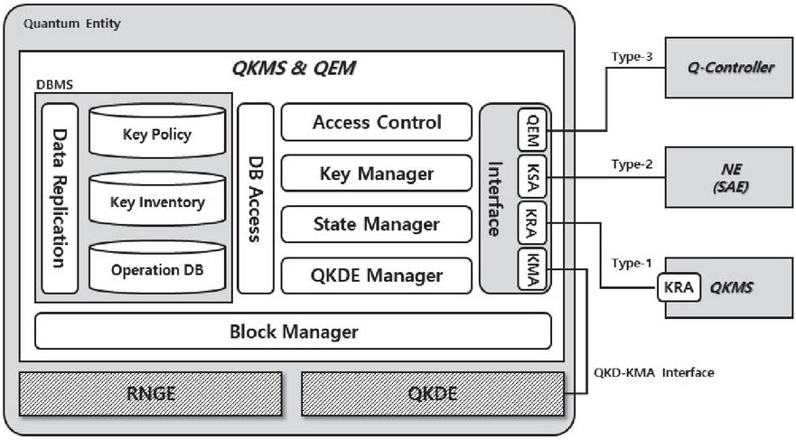
Figure 8 Architecture of QKMS block.
4.3 Deriving QKMS Design Strategy for Test Network in Each Stage
In this section, we define each stage to derive the QKMS design strategy and perform the design and validation processes in each stage. A total of four stages are constituted. Stage 1 is a direct mode key generation process based on the 1:1 configuration of QKMS and QKD. Stage 2 is a direct mode key generation process based on the Q-Controller management system and QKMS/QKD 1:1 configuration. Stage 3 is for validating the key distribution through the key relay of QKMS. Finally, Stage 4 is for validating the bypassing path key generation according to the fault detection between QKMS and QKD.
In Stage 1, two domains are set up, and keys are exchanged with the direct mode between each domain. Due to the absence of a management system, CLI or configuration file is used for the settings of major operations. The key stream generated and exchanged at QKD is sent to QKMS. Then, the stream received at QKMS is reformatted at KMA of QKMS and the key synchronization of the KMA pair is performed. The synchronized key is stored as a master key in the Key Inventory. When a key is supplied from KSA of QKMS to a transmission device, a Type-2 interface is used.
When constructing Stage 1, the required design items include QKMS, QKMS DB, interfaces, and other technical elements. QKMS needs function definitions, block structure, and designs for major blocks. QKMS DB should be able to manage the key storage and operation information. The required interfaces are Type-1 (KMA-KMA), Type-2 (KSA-transmission device), and an interface between QKD and QKMS. Lastly, KMA Key reformat function, Key-ID UUID generation function, hash function, and key induction function should be designed as other technical elements.
The following Figure 9 shows the system components and connection relationships for the validation of Stage 1 design. In two domains, QKMSs are connected through the KM channel, QKDs are connected through the quantum channel, and transmission devices are connected through the data channel. In QKD, quantum keys are distributed through the quantum channel, and the generated keys are stored in QKMS DB. In the transmission devices, a session is established, and the QKMS provides a quantum key required in the session, thereby forming quantum cryptography communication.
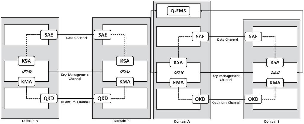
Figure 9 Structure of validation stage 1, 2.
In Stage 2, two domains are set up, and key exchange is performed using the direct mode between each domain. Then, major operation information configuration and key generation requests are made through Q-EMS. The key stream generated and exchange at QKDE is sent to QKMS. Then, the key stream received at QKMS is reformatted by KMA of QKMS and the key synchronization between KMAs is performed. The synchronized key is stored as a master key in the Key Inventory. When supplying the key from the KSA of QKMS to the transmission device, the Type-2 interface is used. KMA of QKMS queries the status of the key periodically and reports the result to Q-EMS.
As the design items required in Stage 2, QKMS requires the QKDE Manager design, Q-EMS design, Q-EMS DB design, and Type-3 interface design in addition to the design items of Stage 1. The Q-EMS design requires the function definitions, block structure, and major block designs. The Q-EMS DB design requires designs for device information and connection relationships. The following Figure 8 shows the system components and connection relationships for Stage 2 design validation. The interoperation between QKMS and Q-EMS is added to the structure of Stage 1.
In Stage 3, three domains are set up and the key exchange is performed in the relay mode through one domain. Then, major operation information configuration, key generation requests, and relay requests are made through Q-EMS. A key stream generated using QRNG (Quantum Random Number Generate) in Domain A is OTP-encrypted with a key stream generated and exchanged by QKD between A and B at QKMS-KMA of Domain A. It is then sent to the QKMS-KMA of Domain B. The QKMS-KMA of Domain B performs the OTP-decryption with a key stream generated and exchanged at QKD between A and B. Afterward, OTP-encryption is performed with a key stream generated and exchanged at QKD between B and C, and it is sent to the QKMS-KMA of Domain C. The QKMS-KMA of Domain C performs the OTP-decryption with a key stream generated and exchanged at the QKD between B and C and stores it in the Key Inventory. As a result, finally, Domains A and C possess the same key data. When a key is supplied from QKMS-KSA to NE (SAE), the Type-2 interface is used, as is the case in Stages 1 and 2. QKMS-KMA queries the status of the key periodically and reports the result to Q-EMS.
The design items required for constructing Stage 3 include the design items of Stage 2. In addition, Q-EMS design requires a definition of the function for key relay and a design of the block structure. For the Q-EMS DB design, a function that can provide the path information for the key relay needs to be designed. In the interface, the key relay function must be designed additionally in the Type-1 interface. Finally, in terms of other technical elements, the path generation function for the key relay must be designed. The following Figure 10 shows the components and connection relationships for the validation of the Stage 3 design. One domain is added to the structure of Stage 2, and the configuration facilitates key relays.
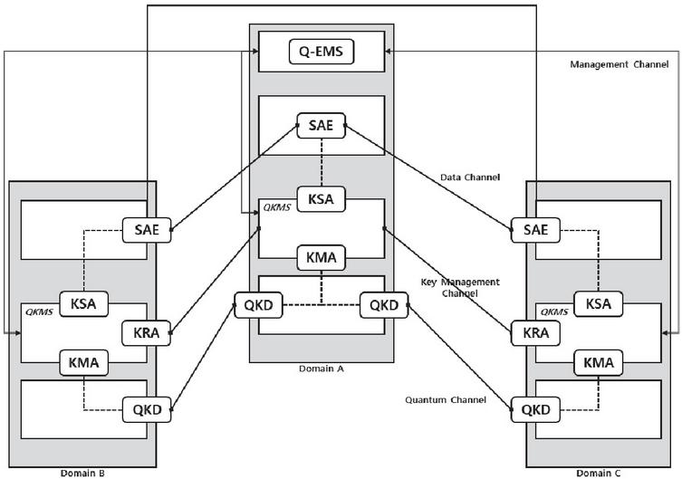
Figure 10 Structure of validation stage 3.
5 Validation QKMS Design
In this section, we validate the design of QKMS and examines the function operations based on the validation results to find the improvements to be made in the design. The design validation is divided into validation based on the integrated QKMS design modeling and simulation and validation based on the application of the QKMS design to the fabricated equipment of Q-IPsec-linked QKD.
The validation based on the integrated QKMS design modeling and simulation aims to check whether the designed parts of QKMS can operate according to the purpose and to find detailed parts that need to be supplemented, which are difficult to consider in the initial design. The validation environment for simulation is constructed. The components include QKMS, Q-EMS, QKDE, NE-TOOL, NE-POTN, and T-EMS. QKMS and Q-EMS are validated by implementing a pilot system, and QKDE is validated by implementing a simulator. NE-TOOL and T-EMS are validated using the RESTAPI message transmission tool, and NE-POTN is validated by implementing POTN equipment.
The validation of the integrated QKMS design is conducted in three stages. As shown in Table 10, the validation plan is divided into three stages, and the functions are validated in each stage.
Table 10 Validation plan for each stage
| Stage | Goal | Scope of Function |
| 1 | To check whether the same key is generated between QKMSs and the same key distributed when requested by the transmission devices | • Load QKD-Key-file and reformat • Perform key synchronization between QKMSs • Receive and respond to the key request |
| 2 | To check Stage 1 functions under the interoperation of Q-EMS and QKMS, and to check the key generation status reporting function | • Bootstrap Inform function • Request Key generation • Report the Key generation status |
| 3 | To check the key relay function between QKMSs | • Generate a key relay path • Request the key relay • Request the key generation between multi-hop domains • Authenticate transmission devices |
In the Stage 1 test procedure, it is checked whether the same key is generated between QKMSs and whether the same key is allocated when a transmission device makes a request. It validates the most basic function of the key management system of quantum cryptography communication. The following Figure 11 shows the structure of the Stage 1 test network. The Stage 1 test procedure consists of seven steps. 1⃝ The QKD simulator generates two types of Key-files to classify Master and Slave. 2⃝ The QKD simulator sends the Key-files to the QKMS on both sides. 3⃝ QKMS extracts the key data from the QKD Key file and reformats them. 4⃝ The validity of the key data reformatted between the QKMSs is tested, and 5⃝ Transmission Device Simulator 1 sends a key request with GetKey to QKMS1. The received Key and Key-ID are checked. 6⃝ If Transmission Device Simulator 2 sends a key request with GetKeyWithID to QKMS2, the Key-ID list received in Step 5 is delivered. 7⃝ Finally, the KEY-ID and KEY received in steps 5 and 6 are compared.
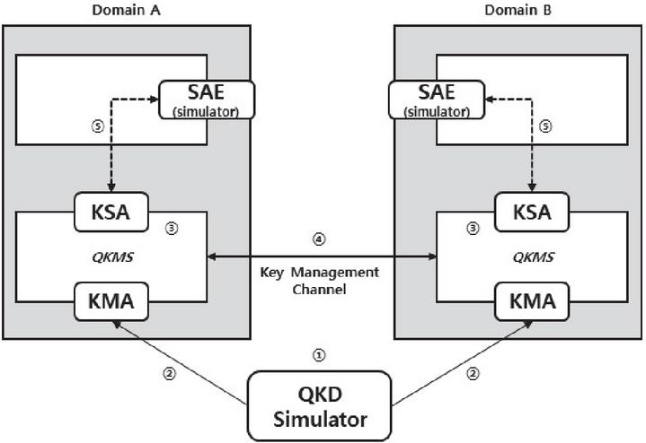
Figure 11 Structure of stage 1 test network.
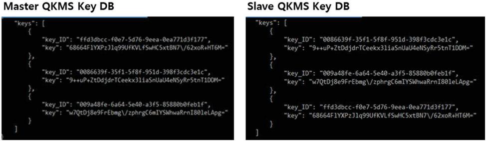
Figure 12 Result of GetKey and GetKeyWithID request message.
The validation was performed in each step. The test results showed that the key exchange between the Master QKMS and the Slave QKMS was successful, and since each transmission device had the same key using GetKey and GetKeyWithID, it was determined the Stage 1 design satisfied the goal. The following Figure 12 shows the GetKey request message result and the GetKeyWithID request message result of transmission devices.
The Stage 2 test procedure checks the Stage 1 functions under the interoperation of Q-EMS and QKMS and checks the key generation status reporting function. The following Figure 13 shows the structure of the Stage 2 test network. The Stage 2 test procedure consists of nine steps. In addition to the Stage 1 test procedure, the following steps are added: a step, in which Q-EMS requests a key generation to QKMS, and a step, in which QKMS reports the key generation status to Q-EMS. 1⃝ First, a bootstrap between QKMS and Q-EMS is performed. 2⃝ Q-EMS sends a key generation request message to QKMS, and then the Stage 1 procedure is performed. (3⃝–9⃝)
The test results showed that Q-EMS collected the connection relationship information of QKD modules; the key exchange between Master QKMS and Slave QKMS based on the request to T-EMS was successful; each transmission device possessed the same key using GetKey and GetKeyWithID. Therefore, the Stage 2 design satisfied the goal. The following Figure 14 shows the result whereby Q-EMS has received the Inform message from each QKMS, and the Figure 15 shows the result whereby QKMS has reported the key generation status to Q-EMS.
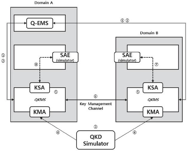
Figure 13 Structure of stage 2 test network.
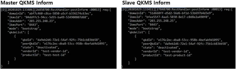
Figure 14 Q-EMS to QKMS receiving inform message.
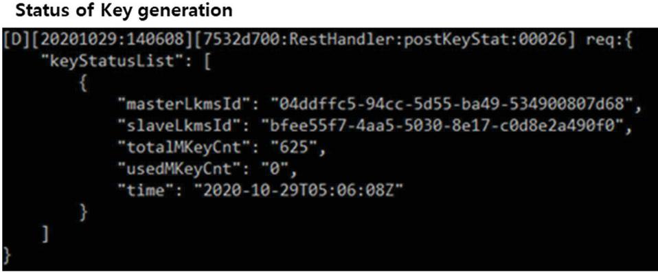
Figure 15 QKMS reports the key generation status to Q-EMS.
Stage 3 is a stage for checking the function of the key relay between QKMSs. The function is validated for the following function scopes: key relay path generation, key relay request function, key generation request between multi-hop domains, and transmission device authentication. In Stage 3, the test network is configured with three domains, as shown in the following Figure 16. The domains are Master, Slave, and Relay domains. Furthermore, before performing the Stage 3 validation, the Q-EMS is set to a state of having the QKDN configuration information, as a prerequisite for the simulation. The following Figure 16 shows the structure of the Stage 3 test network.
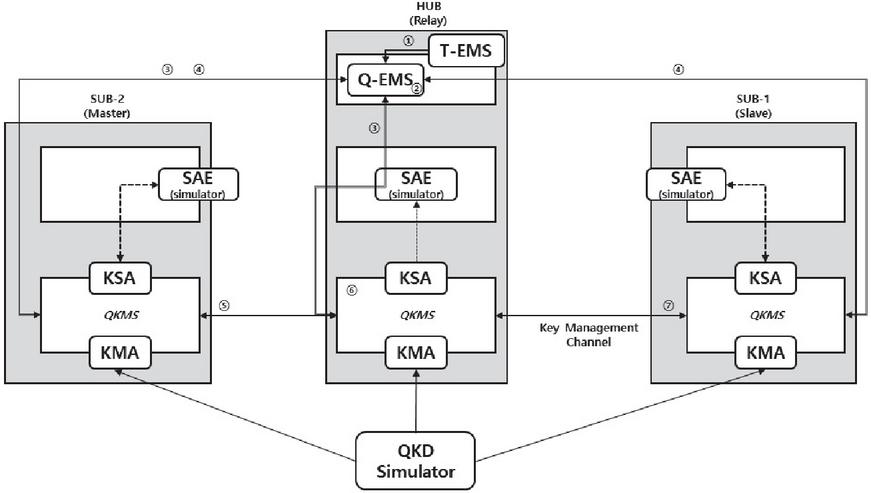
Figure 16 Structure and test procedure of validation stage 3.
The key generation method for the relay mode has the Key-ID generation and random number generation steps. In the Key-ID generation, the Key Id is generated based on the key generation time, reformat order, and QKMS-ID, the rng-tools are used to generate and read random numbers. Stage 3 test procedure consists of seven steps. As in Stage 2, 1⃝ T-EMS sends a key generation request to Q-EMS. Here, the key generation request is sent to Sub-1 domain and Sub-2 domain. 2⃝ Next, Q-EMS uses the QKD network configuration information to generate the shortest path through the BSF algorithm. 3⃝ Q-EMS delivers the relay path the origin and the waypoint, and 4⃝ Q-EMS requests the relay mode key generation to the origin and destination. 5⃝ After generating the relay-key to be sent from the origin to the destination and converting it into an M101 message, it is sent to the waypoint. At the origin, the relay key is stored in the key storage, as a Master-Key that is shared by the origin and the destination. Here, the M101 message is sent after encrypting (XOR) with the OTP-KEY. 6⃝ After receiving the M101 message, the waypoint sends it to the destination. Here, after receiving the message, it is decrypted (XOR) with the OTP-KEY, and after performing Next-QKMS lookup, the decrypted M101 message is encrypted (XOR) with the OTP-KEY and then sent. 7⃝ Finally, the destination receives the message and stores the Relay-Key in the key storage, as a Master-Key that is shared by the origin and destination.
The Stage 3 test results showed that Q-EMS collected the connection relationship information of the OKD modules; the key exchange was successfully performed through the key relay between Master QKMS and Slave QKMS based on the request of T-EMS; each transmission device possessed the same key using GetKey and GetKeyWithID. Therefore, it was determined that the Stage 3 design satisfied the goal. The following Figure 17 shows the result whereby the middle node (relay node) received data and queried the encrypted/decrypted data, and Figure 18 shows the results of Master QKMS and Slave QKMS key queries.
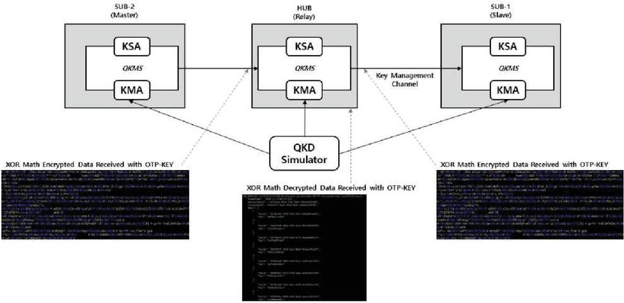
Figure 17 Key and Encryption/Decryption process at relay node.
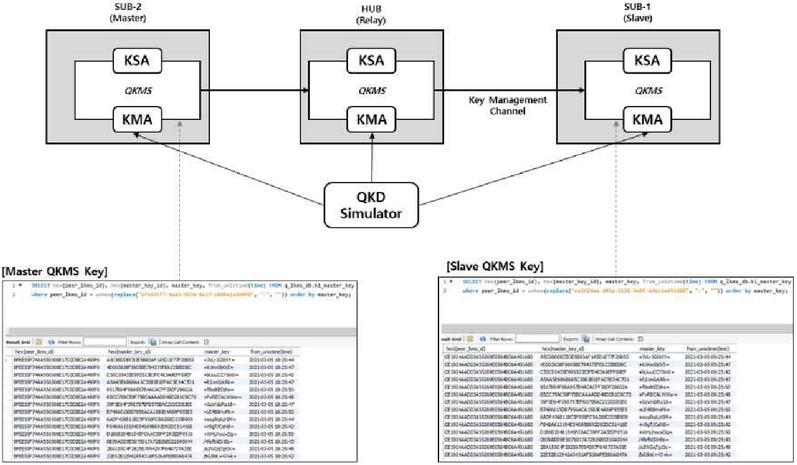
Figure 18 Master and Slave key query result.
The next validation is the validation of QKMS design application to fabricated equipment of Q-IPsec-linked QKD. In this validation, we simulate the QKMS design that will be applied to Q-IPsec service-providing QKD equipment, which will be manufactured in the future, to check whether it can operate for the purpose. Furthermore, this validation aims to find detailed parts that need to be supplemented, which are difficult to consider in the initial design.
First, IPsec consists of Security Association (SA), Authentication Header (AH), Encapsulating Security Payload (ESP), Security Association Database (SAD), and Security Policy Database (SPD). SA is information shared for security services, and AH provides data integrity and origin authentication. ESP is a function that provides data confidentiality along with the AH function, and SAD is a database that defines the parameters related to SA. Lastly, SPD is a database that stores the policies for all inbound and outbound network traffics. The following Figure 19 shows the structure of IPsec. IKEv2 is a protocol mainly used in IPsec. The following Figure 20 shows the operating procedure of IKEv2.
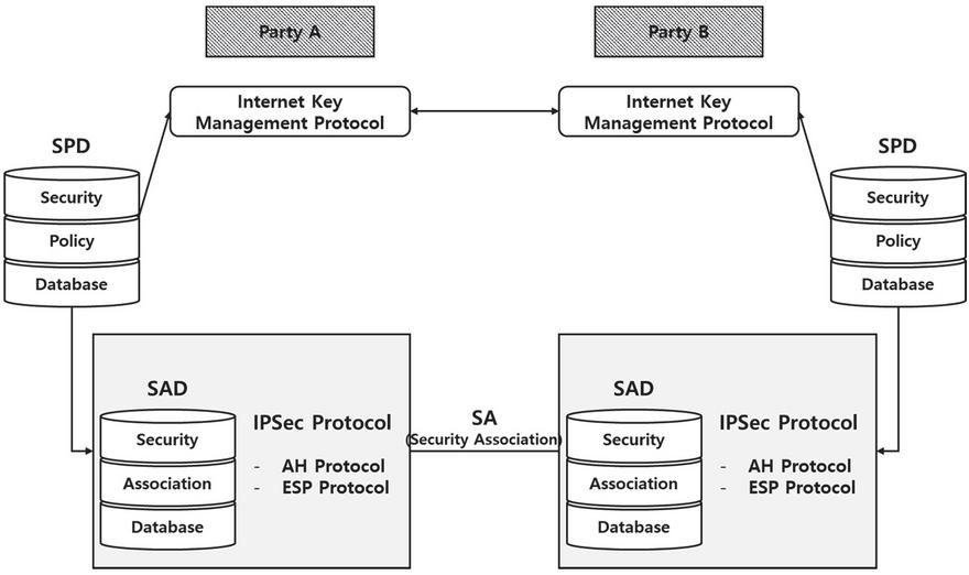
Figure 19 Structure of IPsec.
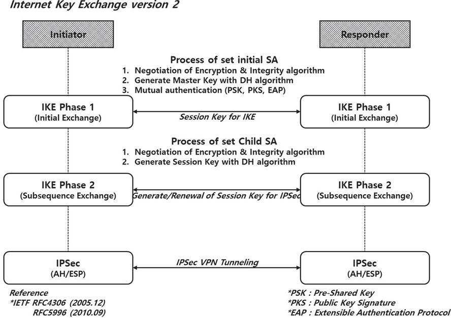
Figure 20 Operating procedure of IKEv2.
For the interoperation of IPsec and QKMS, we need to make changes to use the key supplied by the QKMS as the key used in the SAD configuration. Accordingly, we propose a method of adding a part for interoperating with QKMS when performing IKE key exchange. After Initiator requests a key with GetKey to QKMS, the Key-ID is loaded on the nonce value of Initiator and sent. The responder uses the Key-ID delivered using nonce of Initiator to perform the key request with GetKeyWithID at QKMS. As a result, both sides share the same key. On both sides, the key supplied from each QKMS is used when configuring SAD. The following Figure 21 shows the interoperation structure of QKMS and IPsec.
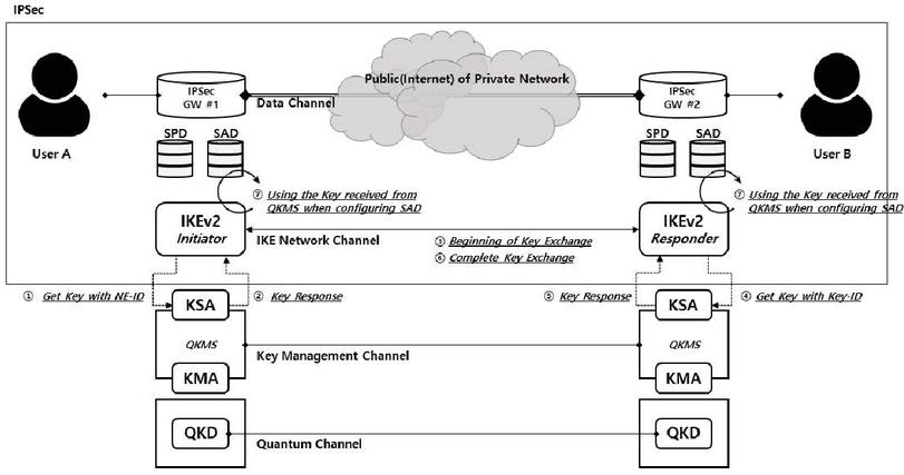
Figure 21 Interoperation structure of QKMS and IPsec.
Table 11 Design supplements according to the validation results
| Item | Supplementation Method |
| Special character encoding problem of interoperating interfaces | Encode with Base64 and send the result (key, hash value, etc.) |
| Efficiency problem of using key resource (If all possible key sizes are generated in advance, some key sizes may be excessive and some key sizes may be insufficient) | KMS generates Master Keys in the same size and supplies them by performing derivation according to the requested size when NE makes a request
– GetKey: there is the size parameter – GetKeyWithId: since there is no size parameter, it is added |
| A problem for generating a unique KEY-ID when KMS performs Key Reformat (the KMS on both sides needs to generate a unique and yet same KEY-ID for each key) | Generate the UUID from Seq information that divided ID, QKD-KEY data, and QKD-PAIR-ID generated from QKD in each GQKD-KEY-FILE |
| A problem for generating a unique DEVICE-ID for each heterogeneous device
– The ID scheme is different between devices |
Generate the UUID from Seq information that divided ID, QKD-KEY data, and QKD-PAIR-ID generated from QKD in each GQKD-KEY-FILE |
| Using the latest hash algorithm when using UUID | In the currently used RFC 4122, it is required to use MD5 or sha1. The method of using the latest hash algorithm should be reviewed. |
| Information of the hash algorithm used needs to be added when verifying the validity of Key | Currently, only the hash result is entered due to the structure of Key-file
– The simulator and pilot for validation uses sha1 |
| CLI and GUI interoperation | Interlink with JSON/REST |
As a result of validating based on the design, the interoperation of QKMS and IPsec was set up, and we checked the result through the IPsec initiator log and the IPsec responder log. In the IPsec initiator log, we confirmed that the key messages were received from QKMS through the IPsec tunnel generation command, information of the KMS to be interlinked, and the key request messages, and finally we confirmed that the SA was configured and the session was established using the key received from the QKMS. Furthermore, in the IPsec responder log, we checked the nonce value received from the Initiator and checked the key message received after requesting a key to QKMS. Finally, we confirmed that SA was configured using the key received from the QKMS and the result was sent to the Initiator.
Based on the design validation results, we summarized the improvements to be made for the development of QKMS with a high degree of perfection. Table 11 shows the design supplements and methods according to the validation results. There are seven items to be supplemented. The special character encoding problem should be resolved in the interoperation interface, and there is a problem regarding efficient management of the Key resource. Furthermore, when QKMS generates a unique Key-ID during Key reformat, it is required to generate the unique and same Key-ID for each key in both QKMSs. Generation of unique Device-IDs is required for devices that are likely to be heterogeneous, such as transmission devices and QKD devices, and we plan to use the latest hash algorithm when using UUID. Finally, when verifying the validity of the key, the information for the hash algorithm used is additionally needed, and CLI and GUI interoperation is required.
6 Conclusion and Future Research
This paper proposed a QKMS design strategy to ensure the physical layer security of the next generation KREONET. To strengthen security in the quantum computing environment, it is planned to construct a quantum cryptography communication network in the next generation KREONET, and a QKMS has been designed for a stable supply of quantum cryptography keys to the nationwide national research network. To design a QKMS, we investigated a QKDN structure suitable for KREONET, designed a KREONET QKMS suitable for the QKDN structure, and performed simulations to validate the design.
The QKDN research and the KMS structure design suitable for KREONET were conducted in four stages. In Stage 1, we designed the interface and connection structure of QKD-QKMS-transmission and exchange equipment. The interface between QKD and QKMS and the interface between QKMS and transmission/exchange equipment were designed by referencing the ETSI and ITU-T standards. In Stage 2, the integrated operation and management structure was designed for the QKD node units and the test network. The layers for constructing QKMS were divided into the network management layer, equipment management layer, QKD layer, and transport layer. Then, the components and roles were defined, and the relationships between the components were illustrated using the layer structure of QKMS. In Stage 3, we adopted a structure of separating the QKD objects and KM (QKMS) objects by referencing the TTA standard to design a heterogeneous quantum key management structure. Furthermore, we proposed a framework that facilitates the expansion of various protocols and functions. In Stage 4, we designed an interlinking structure of trusted nodes and key relays based on the ITU-T standard. Based on the design results over four stages, we confirmed the need for interfaces for management. Hence, four types of interfaces were additionally defined.
The design and strategy of QKMS for application to the national research network were carried out step by step. First, the detailed structure of QKMS linked with the national research network infrastructure was designed in Stage 1. The related standard in each domain was mapped based on the components and structure of each layer defined in Stage 2 of the third specific project. Furthermore, we provided the definitions of the channels for interoperation between components and the definitions for composing the method required for each interoperation interface. In addition, we defined the major functions of KMS and represented the operating procedure of each function in a sequence diagram. We also showed examples of application to the national research network. In Stage 2, we derived a detailed design plan of the integrated QKMS for application to the test network and proposed design directions and a detailed design plan of QKMS and Q-EMS based on them. The detailed design plan includes the definitions of major events (Alarm, Fault, Run) and actions and the definitions of major performance indicators along with the description of the major function configurations for each component, the block configuration and roles, and database design. Finally, in Stage 3, we derived a QKMS design strategy for the test network for each stage, and the design and validation processes were set to be performed over four stages. The design and the design strategy were validated in two stages. In Stage 1, the validation is performed through the integrated QKMS design modeling and simulation. The validation environment was constructed according to the plan of deriving the QKMS design strategy for the test network in each stage. A pilot system of QKMS and Q-EMS was implemented for the test, and the QKM modules were used by implementing a simulator. The validation result showed that the design worked according to the purpose. Stage 2 is for the validation of the KMS design application to the fabricated devices of Q-IPsec-linked QKD. As an interoperation method, we proposed the following method of constructing SAD: the Key-ID is exchanged using the Initiator nonce value of the IKEv2 protocol, and Initiator and Responder receive the key corresponding to the Key-ID from QKMS-KSA.
In a future study, we plan to construct the currently-designed QKMS in the real world instead of simulation and apply it to KREONET for stable quantum cryptography communication. Furthermore, when constructing the system, we will apply the design supplements derived based on the validation results through the simulations to construct a QKMS with a high degree of perfection. In addition, we will construct the system for application to not only IPsec but also various security services.
Acknowledgements
This research was supported by Korea Institute of Science and Technology Information (KISTI).
References
[1] Peter W. Shor. 1994. Algorithms for quantum computation: Discrete logarithms and factoring. In Proceedings of the 35th Annual Symposium on Foundations of Computer Science. IEEE Computer Society Press, 124–134. DOI: http://dx.doi.org/10.1109/SFCS.1994.365700
[2] Frank Arute, et al 2019. Quantum supremacy using a programmable superconducting processor. Nature 574, 7779 (Oct. 2019), 505–510. DOI: http://dx.doi.org/10.1038/s41586-019-1666-5
[3] Charles H. Bennett, Gilles Brassard et al. 1984. Quantum cryptography: Public key distribution and coin tossing. In Proceedings of the IEEE International Conference on Computers, Systems and Signal Processing, Vol. 175. 8. Retrieved from http://www.cs.ucsb.edu/chong/.
[4] Masahide Sasaki. 2011. Tokyo QKD network and the evolution to secure photonic network. In Proceedings of the Conference on Laser Applications to Photonic Applications (CLEO’11), Vol. 1. OSA, Washington, D.C., JTuC1. DOI: http://dx.doi.org/10.1364/CLEO\_AT.2011.JTuC1
[5] Park, Man-Kyu, et al. “A Study of Future Internet Testbed Construction using NetFGA/OpenFlow Switch on KOREN/KREONET.” Journal of the Institute of Electronics Engineers of Korea TC 47.7 (2010): 109–117.
[6] KREONET web site, Retrieved Aug., 6, 2021, from http://www.kreonet.net/
[7] Kim, Dongkyun, et al. “KREONET-S: Software-defined wide area network design and deployment on KREONET.” IAENG International Journal of Computer Science 45.1 (2018): 27–33.
[8] Ma, Xiongfeng, et al. “Quantum random number generation.” npj Quantum Information 2.1 (2016): 1–9.
[9] Krawczyk, Hugo, and Pasi Eronen. “Hmac-based extract-and- expand key derivation function (hkdf).” RFC 5869, May, 2010.
[10] Chip Elliott, David Pearson, and Gregory Troxel. 2003. “Quantum cryptography in practice”, In Proceedings of the Conference on Applications, Technologies, Architectures, and Protocols for Computer Communications (SIGCOMM’03). 227. DOI: http://dx.doi.org/10.1145/863981.863982
[11] Chip Elliott and H. Yeh. 2007. “DARPA Quantum Network Testbed. Technical Report”, BBN Technologies Cambridge, New York, New York. Retrieved from http://oai.dtic.mil/oai/oai?verb=getRecord.
[12] Alexander Sergienko. 2005. “Quantum Communications and Cryptography.” Vol. 2005. CRC Press. Retrieved from http://books.google.com/books?hl=en
[13] Thomas Langer. 2013. “The Practical Application of Quantum Key Distribution”. Ph.D. Thesis. University of Lausanne.
[14] M. Peev, C. Pacher, R. Alléaume, et al. 2009. “The SECOQC quantum key distribution network in Vienna”, New J. Phys. 11, 7 (July 2009), 75001. DOI: http://dx.doi.org/10.1088/1367-2630/11/7/075001
[15] Shuang Wang, Wei Chen, et al. 2014. Field and long-term demonstration of a wide area quantum key distribution network. Opt. Expr. 22, 18 (Sept. 2014), 21739. DOI: http://dx.doi.org/10.1364/OE.22.021739
[16] Qiang Zhang, Feihu Xu, Yu-Ao Chen, Cheng-Zhi Peng, and Jian-Wei Pan. 2018. Large scale quantum key distribution: Challenges and solutions [Invited]. Opt. Expr. 26, 18 (Sep. 2018), 24260. DOI: http://dx.doi.org/10.1364/oe.26.024260
[17] Jane Qiu. 2014. Quantum communications leap out of the lab. Nature 508, 7497 (Apr. 2014), 441–442. DOI: http://dx.doi.org/10.1038/508441a
[18] European Commission. 2017. China to launch world’s first quantum communication network. Retrieved from https://cordis.europa.eu/article/id/122516.trending-science-china-to-launch-worlds-first-quantum-communication-network/en.
[19] ChinaDaily. 2017. Quantum tech to link Jinan governments. Retrieved from http://www.chinadaily.com.cn/china/2017-07/11/content\_30065215.htm.
[20] Martino Travagnin and Adam Lewis. 2019. Quantum key distribution in field implementations. pp. EUR 29865 EN. Retrieved from https://op.europa.eu/en/publicationdetail/-/publication/e93e5bf9-efc3-11e9-a32c-01aa75ed71a1/language-en.
[21] Yong Zhao. 2019. The integration of QKD and security services. In Proceedings of the ITU QIT4N Workshop Shanghai. Retrieved from https://www.itu.int/en/ITU-T/Workshops-and-Seminars/2019060507/Documents/Yong.
[22] Teng-Yun Chen, Hao Liang, Yang Liu, Wen-Qi Cai, Lei Ju, Wei-Yue Liu, Jian Wang, Hao Yin, Kai Chen, ZengBing Chen, Cheng-Zhi Peng, and Jian-Wei Pan. 2009. Field test of a practical secure communication network with decoy-state quantum cryptography. Opt. Expr. 17, 8 (Apr. 2009), 6540. DOI: http://dx.doi.org/10.1364/OE.17.006540arxiv:0810.1264.
[23] F. X. Xu, W. Chen, S. Wang, Z. Q. Yin, Y. Zhang, Y. Liu, Z. Zhou, Y. B. Zhao, H. W. Li, D. Liu, Z. F. Han, and G. C. Guo. 2009. Field experiment on a robust hierarchical metropolitan quantum cryptography network. Chin. Sci. Bull. 54, 17 (2009), 2991–2997. DOI: http://dx.doi.org/10.1007/s11434-009-0526-3
[24] Zheng-fu Han, Fang-Xing Xu, Wei Chen, Shuang Wang, Zhen-Qiang Yin, Yang Zhang, Yun Liu, Zheng Zhou, HongWei Li, Dong Liu, and Guang-Can Guo. 2010. An application-oriented hierarchical quantum cryptography network test bed. In Proceedings of the Optical Fiber Communication Conference. DOI: http://dx.doi.org/10.1364/OFC.2010.OTuK4
[25] Shuang Wang, Wei Chen, Zhen-Qiang Yin, Yang Zhang, Tao Zhang, Hong-Wei Li, Fang-xing Xu, Zheng Zhou, Yang Yang, Da-Jun Huang, Li-Jun Zhang, Fang-Yi Li, Dong Liu, Yong-Gang Wang, Guang-Can Guo, and Zheng-Fu Han. 2010. Field test of wavelength-saving quantum key distribution network. Opt. Lett. 35, 14 (2010), 2454–2456. DOI: http://dx.doi.org/10.1364/OL.35.002454arxiv:1203.4321.
[26] Kaoru Shimizu, Toshimori Honjo, Mikio Fujiwara, Toshiyuki Ito, Kiyoshi Tamaki, Shigehito Miki, Taro Yamashita, Hirotaka Terai, Zhen Wang, and Masahide Sasaki. 2014. Performance of long-distance quantum key distribution over 90-km optical links installed in a field environment of Tokyo metropolitan area. J. Lightw. Technol. 32, 1 (Jan. 2014), 141–151. DOI: http://dx.doi.org/10.1109/JLT.2013.2291391
[27] Länger, Thomas, and Gaby Lenhart. ”Standardization of quantum key distribution and the ETSI standardization initiative ISG-QKD.” New Journal of Physics 11.5 (2009): 055051.
[28] ETSI, “Quantum Key Distribution (QKD); Protocol and data format of key delivery API to Applications,” GS QKD 014, V1.1.1 (2018)
[29] ETSI, “Quantum Key Distribution Control Interface for Software Defined Networks”, GS QKD 015 Quantum Key Distribution (QKD), V1.1.1 (2021).
Biographies

Kyu-Seok Shim is a postdoctoral researcher in Korea Institute of Science and Technology Information (KISTI), Daejeon, Korea. He received his B.S., M.S., and Ph.D. degree in the Department of Computer and Information Science, Korea University, Korea, in 2014, 2016, and 2020, respectively. His research interests include Internet traffic classification, network management, protocol reverse engineering and quantum key distribution.

Yong-hwan Kim is a senior researcher in Korea Institute of Science and Technology Information (KISTI), Korea. He received his B.S. degree from Korea University of Technology and Education, Korea in 2008, and an M.S. and Ph.D. in Computer Science and Engineering from the same university in 2010 and 2015, respectively. He also served as a visiting scholar in Department of Computer Science, State University of New York (SUNY) at Albany in 2014. His research interests include SDN, intelligent network, quantum key distribution, and quantum key management.

IlKwon Sohn is a senior researcher in Korea Institute of Science and Technology Information (KISTI), Daejeon, Korea. He received his B.S., and Unified M.S. & Ph.D. degree in the School of Electrical Engineering, Korea University, Korea, in 2011, and 2018, respectively. His research interests include quantum error correction, quantum key distribution, and quantum computation.

Eunjoo Lee is a postdoctoral researcher in Korea Institute of Science and Technology Information (KISTI), Daejeon, Korea. She received B.S. degree in Physics from Hanyang University, Korea and Ph.D degree in Physics from Korea Advanced Institute of Science and Technology (KAIST). She was a former postdoctoral researcher of quantum optics group in Korea Research Institute of Standards and Science (KRISS). Her interests include fiber optics, single photon generation in telecom band, quantum optics experiment and quantum communication with single photons and continuous variables.

Kwang-il Bae is a senior researcher in Korea Institute of Science and Technology Information (KISTI), Daejeon, Korea. He received his B.S., M.S. & Ph.D. degree in Physics from Sogang University, Korea, in 2013, 2015 and 2021, respectively. His research interests include quantum non-locality, quantum randomness certification and quantum cryptography.

Wonhyuk Lee is a principal researcher in Korea Institute of Science and Technology Information (KISTI), Daejeon, Korea. He received his B.S., and M.S. & Ph.D degree in the School of Electrical, Electronical and Computer Engineering, Sungkyunkwan University, Korea, in 2001, 2003 and 2010, respectively. His research interests include quantum Network Management, Network Performance Enhancement, and QKD network.
Journal of Web Engineering, Vol. 21_5, 1377–1418.
doi: 10.13052/jwe1540-9589.2151
© 2022 River Publishers