Quality Enhancement of 3D Volumetric Contents Based on 6DoF for 5G Telepresence Service
Byung-Seo Park, Woosuk Kim, Jin-Kyum Kim, Dong-Wook Kim and Young-Ho Seo
Kwangwoon University, Korea
E-mail: bspark@kw.ac.kr; kws@kw.ac.kr; jkkim@kw.ac.kr; dwkim@kw.ac.kr; yhseo@kw.ac.kr
Corresponding Author
Received 15 November 2021; Accepted 18 December 2021; Publication 08 March 2022
Abstract
In general, the importance of 6DoF (degree of freedom) 3D (dimension) volumetric contents technology is emerging in 5G (generation) telepresence service, Web-based (WebGL) graphics, computer vision, robotics, and next-generation augmented reality. Since it is possible to acquire RGB images and depth images in real-time through depth sensors that use various depth acquisition methods such as time of flight (ToF) and lidar, many changes have been made in object detection, tracking, and recognition research. In this paper, we propose a method to improve the quality of 3D models for 5G telepresence by processing images acquired through depth and RGB cameras on a multi-view camera system. In this paper, the quality is improved in two major ways. The first concerns the shape of the 3D model. A method of removing noise outside the object by applying a mask obtained from a color image and a combined filtering operation to obtain the difference in depth information between pixels inside the object were proposed. Second, we propose an illumination compensation method for images acquired through a multi-view camera system for photo-realistic 3D model generation. It is assumed that the three-dimensional volumetric shooting is done indoors, and the location and intensity of illumination according to time are constant. Since the multi-view camera uses a total of 8 pairs and converges toward the center of space, the intensity and angle of light incident on each camera are different even if the illumination is constant. Therefore, all cameras take a color correction chart and use a color optimization function to obtain a color conversion matrix that defines the relationship between the eight acquired images. Using this, the image input from all cameras is corrected based on the color correction chart. It was confirmed that the quality of the 3D model could be improved by effectively removing noise due to the proposed method when acquiring images of a 3D volumetric object using eight cameras. It has been experimentally proven that the color difference between images is reduced.
Keywords: 5G telepresence, web-based graphics, point cloud, 3D reconstruction, RGB-D, illumination compensation, color correction.
1 Introduction
Recently, new multimedia technologies in 5G network such as virtual reality and augmented reality in which mixed 3D graphics technology and photo-realistic technology are rapidly developing. In such an environment, a 360-degree free-view-type experience must be basically provided regardless of the user’s location and viewpoint, so an omnidirectional 3D model based on photo-realistic data is becoming essential. The omnidirectional data is largely divided into two categories. The first is omnidirectional data about space [1], and the second is 3D data about objects. Although the expression “omnidirectional” is used for both data simultaneously, there is a big difference in that the camera system for acquiring this information shows an outward-facing and converging inward forms. In this paper, we intend to discuss the field for acquiring 3D photo-realistic objects for the latter case. In this case, like the former, the camera system is composed of multiple views, and the camera’s optical axis has a converging shape or a cylindrical shape to the center. The easiest and most common method for extracting graphics models for 3D objects is photogrammetry [2, 3, 4].
Since the Microsoft research team announced KinectFusion in 2011, research on generating omnidirectional 3D models using multiple RGB-Depth cameras has been actively conducted [5, 6]. Before 3D model generation using multiple RGB-Depth cameras, it is necessary to integrate point clouds of objects acquired from each camera into one coordinate system. This process is called point cloud registration (or reconstruction).
The geometric error of depth image and point cloud data generated from RGB-D camera is determined by sensor accuracy, the distance between subject and camera, interference of structured light between cameras, motion blur caused by the rapid movement of the object, illumination frequency, subject color, etc. It occurs due to various causes [7]. This geometrical error distorts the shape in 3D space. In addition, it has a significant influence on the quality of mesh restoration and data-to-data calibration from depth image and point cloud data. In this paper, geometrical errors in depth images generated while generating depth and 3D objects acquired through RGB-Depth cameras on a multi-view camera system are improved, and geometric errors of point cloud data converted from depth images are improved. Furthermore, we propose a method for improving the quality of a 3D image obtained from RGB-Depth that performs the process.
Many illumination compensation techniques have been studied in various fields. Efforts were made to calculate the shape recognized by human observation by using the characteristics of the human visual system (HVS), which were many early studies. Retinx-based studies are representative. The Retinex theory refers to a method in which the human visual system recognizes the relative brightness with the surroundings rather than recognizing the scene’s brightness at a specific location when recognizing a scene. Among these studies, ACE [8], RACE [9], and the study by Vonikakis et al. [10] are representative. However, among other studies, many studies performed illumination compensation without using the human visual system (HVS) at all. These include the Foused Logarithmic Transform (FLOG) method [11], the Schlick algorithm [12], the wavelet-based algorithm [13], the image enhancement algorithm in the DCT domain [14], the histogram-based transformation method [15, 16], There are illumination invariant color spaces technique [17], genetic algorithm [18], and intrinsic image technique [19]. Although slightly different from these, techniques applied to video sequences have also been studied [20, 21]. This paper proposes an illumination compensation method based on a color optimization function based on the illumination invariant color space. The proposed method is an algorithm that can be integrated with the camera calibration process and provide the same brightness and color for images output from multiple cameras under an indoor studio environment.
This paper is structured as follows. Section 2 describes the 3D volumetric scanning method we use. Section 3 discusses two aspects of techniques for improving the quality of 3D models. Section 4 presents the experimental results on the effectiveness of the proposed method, and Section 5 concludes the paper.
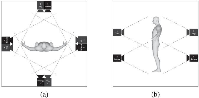
Figure 1 3D point cloud shooting system (a) vertical, (b) horizontal photographing angle and range.
2 Registration of 3D Volumetric Model
This section briefly describes the 3D volumetric scanning system to be implemented and introduces how to generate a photo-realistic 3D volumetric model using this system.
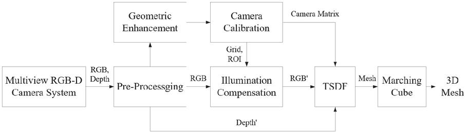
Figure 2 6DoF-based 3D volumetric model sequence generation for 5G telepresence service.
2.1 3D Volumetric Scanning
An RGB-D camera equipped with a depth and RGB sensor is used to generate a photo-realistic-based volumetric 3D model for 5G telepresence service. Since the goal is to generate a 3D model that can be observed from any position, eight pairs of RGB and depth (RGB-D) cameras are placed at various viewpoints of the object. Before generating the 3D model, a point cloud that follows the coordinate system of the depth camera is obtained from each camera using the depth and RGB images taken through the RGB-D camera, and the 3D mesh model is generated using this. The location of 8 RGB-D cameras was configured using stand-type shooting equipment with cameras installed above and below to capture objects from all heights. In addition, and in order to take pictures of the object from all directions, four sets of stands were placed in the front, back, and side four directions. Figure 1 shows the camera system installed in this paper. Figure 1(a) shows the shooting range in the vertical direction, and Figure 1(b) shows the shooting range in the horizontal direction.
Figure 2 shows the photo-realistic-based 3D volumetric model generation algorithm for 5G telepresence service. First, multiple RGB and depth maps are acquired from a multi-view RGB-D camera. RGB and depth sensors contain errors and distortions with distance. Therefore, it is necessary to minimize the geometric error of the depth map when generating a 3D model using an RGB-D camera. Next, filtering is added to the depth camera as a way to remove geometrical errors for depth after shooting [22]. However, if excessive filtering is applied for good quality, motion blur and ghosting may occur. In addition, since the delay between the frames to be photographed increases, it is difficult to remove a desired geometric error through filtering. For this reason, filtering is applied to a minimum when shooting, and geometrical errors are reduced by adding sampling and smoothing operations as post-processing to the captured point cloud [14]. After this pre-processing step, an illumination compensation process combined with the geometric enhancement and the camera calibration are performed. Finally, the color compensation technique is performed independently for each camera, and the compensated RGB images (RGB’) are used as input to the Truncated Signed Distance Function (TSDF) together with the depth map (Depth’) with improved geometrical error [23].
2.2 Extrinsic Calibration
We use a method for obtaining extrinsic parameters of each camera using matching coordinates in point cloud sets for registration [24]. Figure 3 shows the chess board for extrinsic calibration. These parameters are calculated using an optimization algorithm such that the squared Euclidean distance (SED) of the matched coordinates is minimal. The transformation matrix of the coordinate system includes parameters for rotation angles and translation values for each of the , , and axes. After setting one camera as the reference coordinate system, the parameters for converting those of other cameras to the reference coordinate system are obtained. represents the coordinates of the reference camera and represents the coordinates of the remaining cameras. and represent the rotation and translation matrix from each camera to the reference camera. The initial is a unit matrix and is all zero. When Equation (1) is applied with the initial parameter, the result is , and converges to while optimizing [25].
| (1) |
The loss function to be optimized is the average value of SED of and . Equation (2) represents the error function.
| (2) |
The process of differentiating the loss function with respect to the coordinate transformation parameters and updating the parameter to minimize the function can be expressed as Equation (3). is a learning rate as a constant, and a value of 0.01 was used. and are parameters in the and -th iterations, respectively.
| (3) |
When the parameters of each camera are obtained by Equation (3), the transformation from the camera coordinate system to the world coordinate system can be performed using Equation (4), and the point cloud can be aligned based on the unified coordinate system. represents world coordinates (reference camera coordinates), and represents camera coordinates [24, 25].
| (4) |
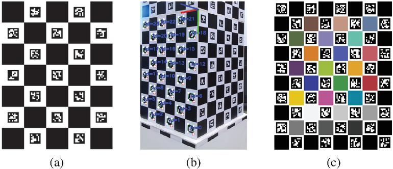
Figure 3 Board for extrinsic calibration (a) Charuco board, (b) world coordinate system obtained through Charuco board, (c) Charuco board with color pattern.
3 Quality Enhancement
3.1 Geometric Enhancement
The quality of a 3D model using multiple RGB-Depth cameras is largely dependent on occlusion, geometrical errors of boundary regions caused by boundary mismatch between color and depth images, and geometrical errors caused by ToF interference. Figure 4 shows the process for solving the geometrical error problem in the depth image. After acquiring the multi-view depth image and the RGB image, a binary image is generated from the acquired RGB image, and the geometric error of the boundary region is removed by applying the mask image to the depth image.
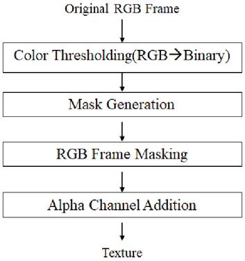
Figure 4 Mask generation algorithm.

Figure 5 Boundary error of (a) point cloud and (b) depth image.
As shown in the image in Figure 5, a geometric error removal filter is implemented as shown in Figure 6 to remove the geometric error of the part with an uncertain boundary located inside the object and the geometric error in which the pixels belonging to the foreground area are scattered into the background.
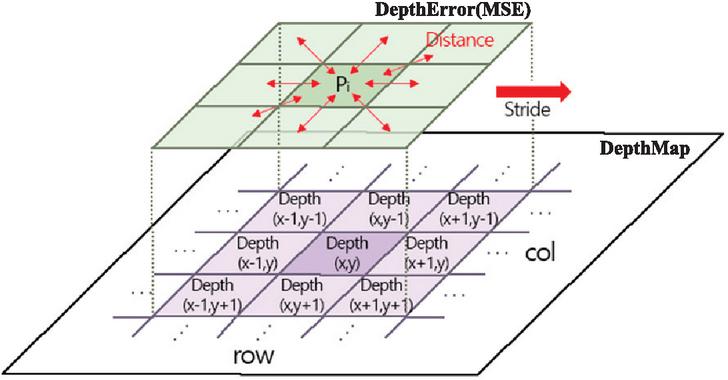
Figure 6 Depth filter structure and operation.
In Figure 5(a), it can be seen that the depth value of the geometric error region is larger than the depth value of the surrounding pixels. Based on the fact that such depth information is adjacent to the and axes in the actual depth image as shown in Figure 5(b), the geometric error of the depth image is defined as Equation (12). While moving the depth image in units of one pixel (Stride), the mean squared error (MSE) between the central pixel and the pixel is calculated.
| (5) |
As shown in Figure 7, if the depth value of is greater than the Mean Squared Error (MSE) with , the central pixel is specified as a geometric error and removed.

Figure 7 Noise data removal example.
3.2 Texture Enhancement
The point cloud registration method proposed in this paper uses both depth and RGB images, and the coordinate system of the final registered model matches the coordinate system of the camera set as a reference. In order to generate an omnidirectional 3D model using 8 RGB-D cameras, first, the RGB image acquisition process (RGB and Depth Capturing) of the chessboard is performed by each camera. Using this image, the initial coordinate transformation parameters are calculated, and the pixel coordinates of the inner corners of the chessboard are obtained. Next, the process of finding the camera position (Camera Position Calculation) is performed. After generating a point cloud for each camera using the depth map and obtaining only the three-dimensional coordinates of the inner corner coordinates of the chess board, the coordinate transformation parameters that minimize the distance between these coordinates are calculated through iterative calculations. After the plane of each board is constructed using the parameters obtained through the process of reconstructing the virtual board (Board Plane Reconstruction), the process of extracting the grid points of the complete chess board (Grid Points Deduction) is performed. After all the grid points are extracted, the RGB image for generating the 3D mesh model is updated by each camera’s color optimization process after selecting the ROI based on this information. This process is shown in Figure 8.
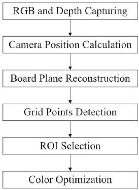
Figure 8 The entire process of camera calibration and color optimization.
The algorithm for color correction is shown in Figure 9. First, to find each of the 24 color areas of the color check chart, we use the marker and corner information of the Charuko board used in the coordinate transformation matrix in Figure 3(c). Then, the corners of each grid are searched from the location information of each marker on the CHARUKO board in the captured image, and a grid of 24 color areas matching the marker ID is set as a region of interest. This process uses the information obtained in the camera parameter generation process.
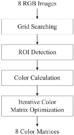
Figure 9 Color compensation algorithm.
The RGB values of each of the 24 colors in the set color check chart are adjusted to be as similar as possible to the RGB values for each color value of the image captured by the color check chart with the camera. This process of making colors similar is called color optimization, and as a result, a color correction matrix (CCM) for RGB colors is obtained. To measure the 24 color values present in the color check chart, the average of all pixel values in the patch area for each color is used. Next, the color close to the original RGB value is repeatedly output by substituting the CCM of each camera into the RGB pixel value of the output image of each camera.
In general, a color image can be stored as a three-dimensional array of (horizontal resolution) (vertical resolution) (number of channels (RGB)) structure. However, in this paper, pixel of the camera output image is expressed as a two-dimensional structure for matrix operation, as shown in Equation (6).
| (6) |
Where the items of the row , is the normalized , , level. The optimized color is represented as defined in Equation (7), which is calculated by multiplying and (CCM) in Equation (8).
| (7) | |
| (8) |
is defied by Equations (9) and (10), where is the original color value for each patch of color. The element of is calculated by dividing the average of with the average of , which configures a diagonal matrix .
| (9) | |
| (10) |
4 Experimental Result
4.1 Experimental Environment
In this experiment, eight Microsoft Asure Kinect cameras were used. The camera placement follows the imaging system described in Figure 10. The upper four units were installed at the height of 0.7 m from the ground to be photographed, and the lower four units were installed at the height of 1.7 m from the floor so that they could be photographed. Setting a threshold value for the depth value made it possible to obtain a point cloud for an object within 0.1 m to 2.5 m. Figure 10 is a photograph of the configured camera system.

Figure 10 Volumetric capturing system with 8 camera pairs.
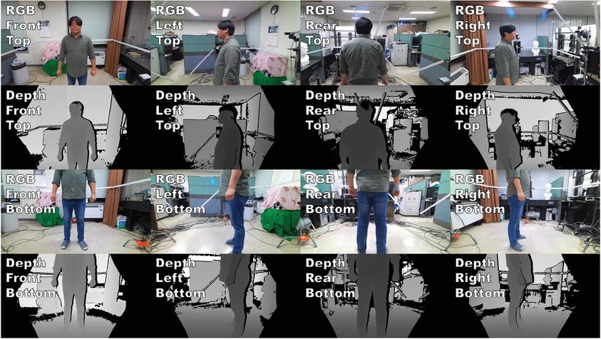
Figure 11 RGB images captured by each camera.
Figure 12 shows the RGB values for 24 patches of the Charuco board-based color correction chart in Figure 4, and the original color value was set.

Figure 12 Standard color checker for optimization.
4.2 Geometric Enhancement Result
Figure 13 shows the output of the image from each step of the algorithm in Figure 4. In Figure 13, it can be seen that the mask generated from the color image effectively separates the foreground and the background to clarify the boundary of the object.

Figure 13 Result images of each step of the proposed geometric enhancement (a) original RGB Frame, (b) mask, (c) RGB image with masking, (d) alpha channel addition texture.
Figure 14 shows the result of removing the geometrical error of the depth image due to illumination and the geometrical error caused by the unclear boundary. This indicates that the geometrical error removal method of the masking method described in this paper can be effectively applied to specifying the geometrical error of the outer angle of an object to the depth image and the point cloud converted from the depth image.

Figure 14 Geometric enhancement result (a) noise caused by lighting, (b) noise reduction result, (c) noise due to unclear boundaries, (d) noise reduction result.
Figure 15(a) is the original depth image, and Figure 15(b) is the result of removing the geometric error inside the object through the filter operation of Equation (5).
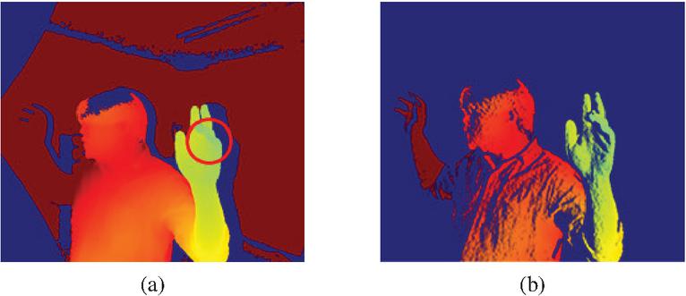
Figure 15 Result of removing boundary error inside object.
Figure 16(a) is a 3D volumetric model generated by registering the point cloud obtained from 8 RGB-Depth cameras. The geometric error estimated through the filter of Equation (5) is indicated in orange. Figure 16(b) shows the filtering result by setting the filter size of Equation (5) to 33 and calculating the direction of the MSE calculation in both the horizontal and vertical directions of the filter center point, and Figure 16(c) shows the direction of the MSE calculation. It shows the filtered result by calculating only in the horizontal direction of the filter center point. The results of Figure 15 confirmed that geometrical errors occurring at the boundary inside the object could be removed by removing the pixels that show a sharp change compared to the surrounding pixels. Also, through the amount of geometric error indicated in orange, it can be seen that it is more effective to calculate by considering all pixels corresponding to the filter position rather than limiting the direction of the MSE operation to one side.
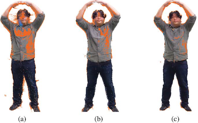
Figure 16 6DoF-based 3D volumetric model for 5G telepresence (a) original point cloud, (b) horizontal filter result, (c) filtering results in all directions.
Table 1 Error of RGB component for each camera
| Color | Camera | Average | ||||||||
| Compensation | 1 | 2 | 3 | 4 | 5 | 6 | 7 | 8 | ||
| Before | R | 17.50 | 18.04 | 21.88 | 21.96 | 9.71 | 19.00 | 33.13 | 37.58 | 22.35 |
| G | 13.25 | 7.92 | 16.75 | 15.38 | 4.71 | 13.88 | 31.79 | 28.38 | 16.51 | |
| B | 3.46 | 2.08 | 1.83 | 2.00 | 3.00 | 6.21 | 22.21 | 14.17 | 4.24 | |
| I | 9.10 | 7.96 | 13.49 | 11.78 | 3.81 | 13.03 | 29.04 | 26.71 | 14.37 | |
| After | R | 3.46 | 3.46 | 4.75 | 3.92 | 2.13 | 4.83 | 5.38 | 5.96 | 3.03 |
| G | 1.71 | 0.13 | 2.21 | 2.29 | 0.04 | 1.42 | 5.08 | 4.25 | 2.10 | |
| B | 2.71 | 6.04 | 4.75 | 0.92 | 5.88 | 3.92 | 0.46 | 1.00 | 1.87 | |
| I | 0.82 | 0.90 | 0.74 | 1.76 | 1.26 | 0.17 | 3.64 | 3.74 | 1.09 | |
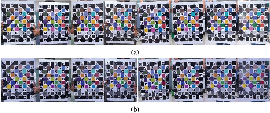
Figure 17 RGB images captured by each camera (a) before, (b) after color correction.
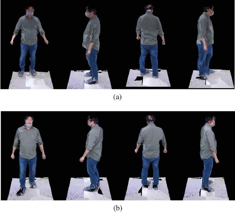
Figure 18 3D reconstruction images (a) before and (b) after color correction.
4.3 Color Enhancement Result
As shown in Table 1, the color image of each camera was compared with the original color value, and the average difference value of each R, G, and B component and the difference value of the brightness component I was obtained. In addition, the difference values before and after applying the color optimization algorithm were compared. In the image taken before using the color optimization algorithm, the R, G, and B components have a maximum difference of 37.58, 31.79, and 2.21, respectively. The brightness value I showed a difference of up to 29.04. The average error values of each camera were 22.35 for the R component, 16.15 for the B component, 4.25 for the B component, and 14.37 for the brightness I. After applying the optimization algorithm, the maximum difference value of the R component was lowered to 5.96, the maximum difference value of the G component was 5.08, and the maximum difference value of the B component was lowered to 6.04. The average difference values for each camera were 3.03 for the R component, 2.10 for the G component, 1.87 for the B component, and 1.09 for the I component. These results confirmed that the difference in color components and brightness values between images captured by each camera was significantly reduced by applying the color optimization algorithm compared to before the application of the algorithm.
Figure 17 shows the images before and after applying the color optimization algorithm to the color images of 8 multi-view cameras captured in the system. Figure 18 shows the 3D volumetric model restored through the process of Figure 8 for the input image of Figure 11.
5 Conclusion
In this paper, a technique for improving the quality of a 6DoF 3D volumetric model generated using a multi-view camera for 5G telepresence service was considered in terms of geometry and color. First, a method of removing a geometric error outside an object by applying a mask obtained from a color image and applying a combined filtering operation to obtain a depth value difference between pixels inside an object is presented. Next, an illumination compensation method for images acquired through a multi-view camera system was proposed. Finally, an image input from all cameras was corrected by obtaining a color conversion matrix defining the relationship between the eight obtained images using a color optimization function and applying it to all pixels of the input image.
Each experimental result confirmed that the proposed method could improve the geometric quality of the 3D model by effectively removing the geometric error from the depth image and point cloud. In addition, through each image before and after correction, it was confirmed that the color difference between cameras was significantly reduced compared to before applying the color optimization function even in the texture restoration result of the 3D model.
Funding
This research was supported by Basic Science Research Program through the National Research Foundation of Korea (NRF) funded by the Ministry of Education in 2020 (NRF-2018R1D1A1B07043220). This work was supported by Institute of Information & communications Technology Planning & Evaluation (IITP) grant funded by the Korea government (MSIT) (2020-0-00922-002, Development of holographic stereogram printing technology based on multi-view imaging).
References
[1] Ralf Schäfer, Peter Kauff, Robert Skupin, Yago Sánchez, and Christian Weißig. Interactive steaming of panoramas and vr worlds. SMPTE Motion Imaging Journal, 126(1):35–42, 2017.
[2] T.H.D. Nguyen, T.C.T. Qui, K. Xu, A.D. Cheok, S.L. Teo, Z.Y. Zhou, A. Mallawaarachchi, S.P. Lee, W. Liu, H.S. Teo, L.N. Thang, Y. Li, and H. Kato. Real-time 3d human capture system for mixed-reality art and entertainment. IEEE Transactions on Visualization and Computer Graphics, 11(6):706–721, 2005.
[3] Zongqian Zhan, Gaofeng Zhou, and Xue Yang. A method of hierarchical image retrieval for real-time photogrammetry based on multiple features. IEEE Access, 8:21524–21533, 2020.
[4] Photogrammetry, July 2021.
[5] Soon-Yong Park and Sung-In Choi. Convenient view calibration of multiple rgb-d cameras using a spherical object. KIPS Transactions on Software and Data Engineering, 3:309–314, 08 2014.
[6] Shahram Izadi, Richard A. Newcombe, David Kim, Otmar Hilliges, David Molyneaux, Steve Hodges, Pushmeet Kohli, Jamie Shotton, Andrew J. Davison, and Andrew Fitzgibbon. Kinectfusion: Real-time dynamic 3d surface reconstruction and interaction. In ACM SIGGRAPH 2011 Talks, SIGGRAPH ’11, New York, NY, USA, 2011. Association for Computing Machinery.
[7] Kyung-Jin Kim, byung-Seo Park, Dong-Wook Kim, and Young-Ho Seo. Point cloud registration algorithm based on rgb-d camera for shooting volumetric objects. Journal of Broadcast Engineering, 5(5), Sep 2019.
[8] Alessandro Rizzi, Carlo Gatta, and Daniele Marini. A new algorithm for unsupervised global and local color correction. Pattern Recognition Letters, 24(11):1663–1677, 2003. Colour Image Processing and Analysis. First European Conference on Colour in Graphics, Imaging, and Vision (CGIV 2002).
[9] Edoardo Provenzi, Carlo Gatta, Massimo Fierro, and Alessandro Rizzi. A spatially variant white-patch and gray-world method for color image enhancement driven by local contrast. IEEE Transactions on Pattern Analysis and Machine Intelligence, 30(10):1757–1770, 2008.
[10] V. Vonikakis. Fast centre–surround contrast modification. IET Image Processing, 2:19–34(15), February 2008.
[11] H.-S. Le. Fused logarithmic transform for contrast enhancement. Electronics Letters, 44:19–20(1), January 2008.
[12] Christophe Schlick. Quantization techniques for visualization of high dynamic range pictures. Photorealistic Render Techn, 03 1998.
[13] Wanpeng Cao, Rensheng Che, and Dong Ye. An illumination-independent edge detection and fuzzy enhancement algorithm based on wavelet transform for non-uniform weak illumination images. Pattern Recognition Letters, 29(3):192–199, 2008.
[14] Chung-Ming Kuo, Nai-Chung Yang, Chih-Shan Liu, Pi-Yun Tseng, and Chi-Kao Chang. An effective and flexible image enhancement algorithm in compressed domain. Multimedia Tools and Applications, 75(2):1177–1200, Jan 2016.
[15] Teck Long Kong and Nor Ashidi Mat Isa. Enhancer-based contrast enhancement technique for non-uniform illumination and low-contrast images. Multimedia Tools and Applications, 76(12):14305–14326, Jun 2017.
[16] Yu-Ren Lai, Ping-Chuan Tsai, Chih-Yuan Yao, and Shanq-Jang Ruan. Improved local histogram equalization with gradient-based weighting process for edge preservation. Multimedia Tools and Applications, 76(1):1585–1613, Jan 2017.
[17] Shiv Ram Dubey, Satish Singh, and Rajat Singh. A multi-channel based illumination compensation mechanism for brightness invariant image retrieval. Multimedia Tools and Applications, 74:11223–11253, Dec 2015.
[18] Yunbo Rao, Lei Hou, Zhihui Wang, and Leiting Chen. Illumination-based nighttime video contrast enhancement using genetic algorithm. Multimedia Tools and Applications, 70(3):2235–2254, Jun 2014.
[19] Jianbing Shen, Xiaoshan Yang, Yunde Jia, and Xuelong Li. Intrinsic images using optimization. In CVPR 2011, pages 3481–3487, 2011.
[20] Yanxiang Han and Zhisheng Zhang. An efficient estimation method for intensity factor of illumination changes. Multimedia Tools Appl., 72(3):2619–2632, October 2014.
[21] Alok Kumar Singh Kushwaha and Rajeev Srivastava. Automatic moving object segmentation methods under varying illumination conditions for video data: comparative study, and an improved method. Multimedia Tools and Applications, 75(23):16209–16264, Dec 2016.
[22] Sebastian Ruder. An overview of gradient descent optimization algorithms, 2017.
[23] Brian Curless and Marc Levoy. A volumetric method for building complex models from range images. In Proceedings of the 23rd Annual Conference on Computer Graphics and Interactive Techniques, SIGGRAPH ’96, page 303–312, New York, NY, USA, 1996. Association for Computing Machinery.
[24] Kyung-Jin Kim, Byung-Seo Park, Jin-Kyum Kim, Dong-Wook Kim, and Young-Ho Seo. Holographic augmented reality based on three-dimensional volumetric imaging for a photorealistic scene. Opt. Express, 28(24):35972–35985, Nov 2020.
[25] Kyung-Jin Kim, Byung-Seo Park, Dong-Wook Kim, Soon-Chul Kwon, and Young-Ho Seo. Real-time 3d volumetric model generation using multiview rgb-d camera. Journal of Broadcast Engineering, 3(3), May 2020.
Biographies
Byung-Seo Park has received his B.A degree in 2021 from Dept. of Business Administration of Kwangwoon University in Seoul, Korea. He is a candidate of Ph.D. program in Dept. of Electronic Materials Engineering, Kwangwoon University in Seoul, Korea. His research interest is 3D graphics, 2D and 3D image processing, Real Time Volumetric Reconstruction.
Woosuk Kim has received his Associate’s degree in 2015 from Department of Digital Electronics of Osan University and he has received his Bachelor’s degree in 2018 from Department of Electrical Electronic and Control Engineering of Hankyong National University. He is a candidate of Ph.D. program in Dept. of Electronic Materials Engineering, Kwangwoon University in Seoul, Korea. His research interest is Digital holography, Image Super-resolution, 2D and 3D image processing.

Jin-Kyum Kim has received his M.S degree in 2021 from Dept. of Electronic Materials Engineering of Kwangwoon University in Seoul, Korea. He is now a Ph.D of Department of Electronic Materials Engineering and a director of Artifical Intelligence Research Center at Kwangwoon University in Seoul, Korea. His research interests include 3D graphics, 2D and 3D image processing, digital holography, wavelet transform, zerotree compression and parallel processing.
Dong-Wook Kim has received his B.S. and M.S. degree in 1983 and 1985, respectively, from Dept. of Electronic Engineering of Hanyang University in Seoul, Korea and his Ph.D. degree in 1991 from Dept. of Electrical Engineering of Georgia institute of Technology in Atlanta GA, USA. He is a full professor of Dept. of Electronic Materials Engineering in Kwangwoon University, Seoul, Korea. His research interests include digital system design, digital testability and design-for-test, digital embedded systems for wired and wireless communication, design of digital signal processor.
Young-Ho Seo has received his M.S and Ph.D degree in 2000 and 2004 from Dept. of Electronic Materials Engineering of Kwangwoon University in Seoul, Korea. He was a researcher at Korea Electrotechnology Research Institute (KERI) in 2003 to 2004. He was an assistant professor of Dept. of Information and Communication Engineering at Hansung University in Seoul, Korea. He was a visiting professor of University of Nebraska at Omaha, USA. He is now a full professor of Department of Electronic Materials Engineering and a director of Artifical Intelligence Research Center at Kwangwoon University in Seoul, Korea. His research interests include 3D graphics, 2D and 3D image processing, digital holography, real-time system, and parallel processing.
Journal of Web Engineering, Vol. 21_3, 729–750.
doi: 10.13052/jwe1540-9589.2138
© 2022 River Publishers