PLEC, A Participative Process for GUI Prototyping
Javier J. Gutiérrez1, Carlos Arévalo1 and David Lizcano2
1Escuela Técnica Superior de Ingeniería Informá tica, Sevilla, Spain
2 School of Computer Science, Universidad a Distancia de Madrid, UDIMA, Madrid, Spain
E-mail:javierj@us.es
Received 18 April 2019;
Accepted 01 July 2019
Abstract
GUI is one of the key aspect of an information system from the point of view of customers and users. This paper introduces PLEC, a participative process for designing GUI interfaces with the collaboration of the final users and stakeholders. Participants do not need technical knowledge of GUI prototype. A case study has been developed and carried out to verify if PLEC process is feasible.
Keywords: GUI, prototyping, team work.
1 Introduction
The Graphical User Interface also known as GUI is, in our opinion, the element of a software system more noticeable for final users. Therefore, final users are very concerned about how GUI is created. Even, a user may measure the quality of an application through its GUI. It is also a meeting point where technical and non-technical participants gather with each other. Final users do not discuss the design of the data access layer or the implantation of a distributed architecture but may be critical with the GUI.
This behaviour imposes a different way to work with GUI. In its development, the management of ideas, needs and the expectative of the final users are more important than other parts of the system. Unsuccessful communication is often at the root of inadequate requirements specification [1].
Usually, developers interview customers and stakeholders to discover the functionality of the system and the requirements for the GUI. After some time, customers and stakeholders could check what the developers think is the best way to implement of what they have understood from the interviews. Moreover, maybe the customer did not remember the interview or even the context of the customer has changed.
This paper proposes a change of the paradigm. Instead of talking with the customers, PLEC proposes working with customers and stakeholders for developing a GUI prototype in one workshop. After that, developers and stakeholders share the same vision of the GUI system and developers may work aligned with their customers. The goal of this paper is to introduce a process, called PLEC, for obtaining a GUI prototype with the active participation of users and other nontechnical stakeholders. The goals of this process are, first, help users to think and decide which GUI they want for their systems and, second, to obtain a visual prototype that user can validate.
Next paragraphs list the original contributions of this paper:
- A LEGO© SERIOUS PLAY© (LSP from now) [2] workshop for developing a LEGO® model describing the main goals of the GUI.
- A translation process to create an executable prototype ofthe GUI designed in the LSP workshop.
- A case study to evaluate the prototyping of GUIs using LSP and the translation process.
Above contributions are called PLEC process from here. Contribution 1 (LSP workshop) allows gathering from technical and non-technical participants to build a common GUI with the support of all the attendees in the workshop. GUI result is modelled using LEGO® blocks.
Contribution 2 (translation process) helps to translate the GUI from LEGO blocks to graphical components, then, to an executable GUI prototype for the participants of the workshop.
Moreover, the authors of this paper have established a set of requirements for the PLEC process. These requirements are listed below and explained in following paragraphs:
- PLEC process should be held in one or two sessions only.
- PLEC process should end with an interactive GUI prototype or, at least, with enough information to create a GUI prototype the day after.
- GUI prototype should be built using tools that allow the participation of all members in the workshops.
GUI prototypes are perishable work. Their only utility is to validate ideas and provide guidelines for the implementation of the real GUI. Therefore, the time spent in prototyping must be according to the benefits of the prototype. For this reason, if PLEC takes too long, people will be neglected to assist. Consequently, we have introduced requirement 1 to create a dynamic that must be done in one day or if possible half of the day.
Requirement 2 is necessary to resolve both previous problems. An interactive GUI is the final result that we are searching with PLEC process. Participants do not want any prototype, but a prototype with the ideas and the agreements of everybody in the workshop. Hence, the result must be a GUI prototype or at least it must be built the day after and the interaction must include the navigation among screens at least.
The GUI prototype must be developed for people who has attended to the workshop. This is the best way to ensure the outcome of the workshop and the meaning of the LEGO® models created. The GUI prototype could be developed by an engineer with experience in GUI tools after the workshops, but we introduce requirement 3 to encourage creating the prototype as a part of the workshop (separating the workshop in two days if necessary), involving all the participants.
Results of this paper allows to schedule a meeting with users, stakeholders, developers and other people involved in the creation of a GUI of a system under development, create a LEGO® model with the main ideas of the prototype, translate those ideas into an interactive prototype and re-evaluate that prototype with the participants. Case study section exposes examples of the results of PLEC process.
The paper is organized as follows. Section 2 exposes background works. Then, Section 3 describes the PLEC process in detail, including the LSP workshop and the teamwork techniques for defining the prototype from the results of the workshop. Afterwards, Section 4 exposes a case study applying PLEC in a real project. Finally, Section 5 exposes conclusions.
2 Background
Section 2.1 exposes papers related to the application of LSP in software engineering. Then, Section 2.2 exposes papers related to GUI prototyping.
2.1 LSP in Software Engineering
There are approaches for introducing gamification in requirements. For example, paper [3] presents a tool-supported collaborative requirements prioritisation process, which uses game elements to engage distributed users and stakeholders to contribute to the overall decisionmaking process. However, authors of this paper have found little evidences of the use of LEGO SERIOUS® PLAY® in software engineering.
Authors of this paper have used the Google Scholar search engine with sets of keywords like “Lego serious play software”, “Lego serious play engineering”, “Lego serious play management” and “Lego serious play requirements”. Several results have been found but those papers are focused on creativity thinking or developing competences in a university context. Papers found that describes how to apply LSP into a software engineering context are analysed in the following paragraphs.
Paper [4] describes a LSP workshop for discovering requirements. This paper covers the modelling of actors, functional requirements and the relation between these two elements. The expected duration for this workshop is about 3 hours.
We have facilitated some workshops for requirement (see Section 5) and 3 hours is not enough. Usually a workshop for discovering requirement takes among 4 and 6 hours for small systems and a full day for the biggest ones. The workshop from [6] is focused on asking participants what requirements they want to but we have found that this approach does not provide good results. Section 4 introduces a different LSP workshop focused on the goals of the actors and how to achieve those goals.
Paper [5] describes an application of LSP for teaching software engineering in lessons of 75 minutes long. However, the process of the warm-up activity of a LSP workshop could take 40 or 50 minutes, so a 75 minutes classroom is probably not enough for developing a good LSP workshop.
Previous references exposes an immature state of the art. There are little evidences of the application of LSP in software engineering. Existing works has shown a basic level of application and seems to be immature.
2.2 GUI Prototyping
Paper [6] present and discuss GUI, the Graphical User Interface interaction interview, a method used to remotely discuss, develop and test GUI prototypes with users and stakeholders. LSP workshop introduced in this paper have a similar goal, however instead of discussing about a prototype, the PLEC process is focused on developing prototypes working all together.
Paper [7] explores using mock end-user graphical interface construction, supplemented with textual argumentation as a means of communicating the software requirements information to software requirements analysts and providing automated assistance for requirements analysts that are examining this information. The elicitation tool has been developed and used to collect data from approximately 75 students.
Papers [8, 9] introduce one of the major web end-user software engineering (WEUSE) challenges, specifically, how to verify and validate software products built using a life cycle enacted by end-user programmers. Although their topic is out of the scope of this work, both papers introduces a comprehensive work with web components for developing tools to build web interfaces for non-expert users. Some of their ideas are applicable to PLEC due PLEC goal is that non-technical participants could build a prototype of the web GUI for a system under development.
3 PLEC Process
PLEC process is composed of four steps. First step is a checkpoint to be sure that all participants share the same vision of the project. If there is not a common view, or some participants have no idea of the vision of the project, the participants have to share the vision. A simple way to set a common vision is answering the questions from Table 1. Table 1 introduces a checklist to assure the project is mature enough to perform a LEGO® SERIOUS PLAY® GUI workshop. Participants should answer the questions by their own, then, share the results to detect inconsistences. Answers for question in Table 1 can be short statements like the ones included in the case study at the end of this paper.
After a shared vision is obtained, participants take part in a LSP workshop. As aforementioned, the goal of the LSP workshop is to build a structure of the GUI with the participation of all members in the workshop. The result of the LSPworkshop is a set of LEGO® buildings, which are metaphors of the elements of the GUI.
Table 1 Checklist
Id Question
1 Which is the goal of the system under development?
2 Which kind of users are the main target of the system under development?
3 Which is the main functionality of the system under development?
People who has attended to the workshop should build the GUI prototypes, no matter their technical skill in building prototypes. This is the best way to preserve the outcome of the workshop and the meaning of the LEGO® models created. An engineer with experience in GUI tools could build GUI prototypes after the workshops, but the participant component will get lost and the result of the prototype will not be a teamwork. Some participants could argue that their ideas from the workshop are rejected from the final prototype. This is the reason why PLEC process include additional activities for creating the GUI prototype from the results of the LSP workshop also in a participative way.
Next step starts with the results of the LSP workshop. In this step, participants translate the metaphors of how the GUI should be into a GUI prototype. First, participants search for real user interfaces and they gather ideas about how to implement their metaphors into GUI components. Then, they draw GUI prototypes on paper sheets and they vote for their best ideas. Finally, all good ideas are implemented into the final GUI prototype.
Figure 1 depicts an overview of the PLEC process.
Next section describes the four steps from the PLEC process (Figure 1) in detail. Section 3.1 introduces LSP. Then Section 3.2 exposes the details of the LSP workshop for creating a common GUI. After that, Section 3.3 introduces the activities to translate the LEGO® models into a GUI prototype.
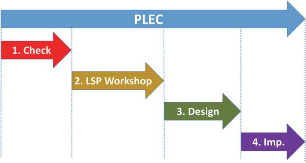
Figure 1 PLEC process overview.
3.1 LSP in Software Engineering
LSP is a method that enables constructive reflection and dialogue processes. Participants use LEGO bricks to create models that express their thoughts, reflections and ideas. The LSP method is built upon basic knowledge about how people best learn and develop. This learning process implies four steps:
- First step should help people connect to what they are going to explore, and to understand the context and meaning of what they are about to learn more about.
- Second step is to involve people in a process where they create a product connected to those targets of exploration, involving their own knowledge, reflections and creative skills as well on their own hands.
- Third step should help people think about what they have created and look deeper into their own reflections and their own product, in order to become aware of what their explorations have brought to them, and to gain more insights.
- Fourth step is that people get the chance to connect their newly obtained knowledge to new explorations they would want to pursue.
LSP workshop typically takes at least one day but, at its shortest, it should last three or four hours. Furthermore, it could take even more than one day.
LSP does not forces any restrictions about the time of a workshop, if there are valuable results, then the workshop may go on. However, if the time needed for a workshop is too long, people may be neglected to assist. Consequently, we have introduced requirement 1 to create a dynamic that must be done in one day only or if possible, half of the day.
A LSP workshop establish a compromise among the whole participants. Participants create a solution all together using the contributions of everyone in the workshop. Furthermore, this dynamic also keep on mind that no one should change the solution after the workshop ends. Results should be kept as they were built during the workshop.
The meaning of the LEGO® models stay in mind for a while. However, after some days working in other issues, that meaning goes away.
Any work in LSP begins creating an individual model. This means, everybody build their own LEGO® model. Sometimes, these models are enough to resolve the question, but some other times, additional techniques are essentials to create a global and shared solution.
The only role defined in LSP is the facilitator, who have the following responsibilities:
- She design the workshop according to the desired result.
- She facilitates the workshop.
More than one facilitator may work in the same LSP workshop. The LSP guidelines suggest a facilitator for each 10–12 participants. All workshops in the case study that will be introduced in a future section have been promoted by a certified facilitator in LSP.
LSP introduces no restrictions about participants. Everyone involved with the goal of the workshop may take part. There is no need of any specific training before the workshop since some introductory exercises are performed, so everyone have the chance to learn how to participate in a LSP workshop before starting the real work.
3.2 LSP Workshop
A LSP workshop is a list of questions that the participants must answer building LEGO® models and exploring the meaning of those models. Therefore, the design of a LSP workshop is the compilation of a list of questions to dive into the knowledge.
This section explains in detail the LSP workshop designs for generating a prototype of the GUI of a system under test.
The scope of the workshop is the design of a GUI prototype. Other aspects of the system under development, like user roles/actors, functionality, non-functional requirements, etc. are out of the scope of the workshop. Some topics that may arise during the workshop are listed below from the practical experience of the authors of this paper.
- Scope of the application. For a GUI workshop the scope of the system under development have to be defined using different process like the Project Schedule from the Project Management Body of Knowledge, a yes/no list of functionality from Agile Inception, a Story map of the system, etc.
- Goals of the application.
- User roles or actors. One key aspect for designing a GUI is to know the people, users or actors who will interact with the system. These information should be identified in the form of actors (from UML) user roles (from), Personas, empathy maps, etc.
- Participants. You need to know the participants of the project in order to call the correct people into the workshop.
Facilitator of the workshop should avoid previous topics and keep the focus on the GUI. Therefore, a previous work of defining the project have to be done because participants need to have all the information regarding the system and share the same vision. This section describes the workshop for creating GUI prototypes in depth. The blueprint of the workshop is Tables 2 and 3.
Workshops from Table 3 follows the guidelines for designing workshops in LSP. These guidelines are described next, before simplifying the activities in the workshop.
All LSP workshops should begin with an introduction and a preparation step. In the introduction, the facilitator explains the goal of the workshop and the rules. For example, one common rule is to avoid the use of mobile devices because they may break the a-ha moments. These activities are always the same (as defined in the LSP official documentation). They are used to avoid the fear of working with LEGO® and understand the main dynamics, like thinking with hands and sharing the meaning of a model. After the training activities are over, the real work should start.
Table 2 Description of the workshop
| Name of the Workshop | Web Application Prototype |
| Goal of the workshop | To obtain a set of models that describe a web application |
| Number of participants | Between 3 and 12 people |
| Profile of the participants | Knowledge of the problem to solve with the web application |
Table 3 Workshop schedule
| Goal | Duration | Description |
| Introduction | 5 min. | |
| Warming up | 10:15/40 min. | Standard LSP activities to set the stage and teach the method to the participants. |
| Main page | 30 min. | Each participant build their vision for the main page of the application. Then, the group create a shared model with contributions from all of them. |
| Sections | 30 min. |
|
| Details | 60 min. |
|
| Navigation | 60 min. | Connect models among them. Each connection means a way to go from a page to another. |
| Conclusions | 20 min. | To make an overview of the story of the LEGO models |
Next activity from the workshop is building the main page. The facilitator ask participants to adopt the role of a user who came to the application. Which kind of information they get? What things can be done? At this moment, other pages where the user may go are not relevant. Facilitator should keep participants focused on the main goal and, in future activities, other pages will be explored and linked to the main page.
Once everyone has clear understanding of the goal and rules of the workshop, the facilitator starts the training.
The first answers for this question are stand-alone LEGO® models, which means that every participant have their own vision of the main page. Those models have to converge into a unified model for the main page. Facilitator uses the technique of building a common model described in Section 3.
This final model of the main web page is placed in the centre of the table and the facilitator introduces the next activity from Table 4.
Next activity is thinking about which other pages may the user visit and what is the goal for those pages, what kind of information is needed, what actions the user may perform, etc. In this case, participants are free for building as many models as they want and to introduce as many different pages as they want to.
A facilitator should try to constraint the time for building so no one of the participants should build more than 2 or 3 pages. Only one model is also a valid result, we are not searching for several ideas but for interesting ones.
When each participant is sharing their stories about the pages that they have built, facilitator should ask to the group if they have built the same or similar page, the rest of the group could agree or they could think any important element is missed. With this dynamic, shared models of other pages are built.
Table 4 Participant characterization survey
|
I have programmed GUI less than a year ago I worked with GUI prototyping tools less than a year ago I have programming knowledge of GUI I have knowledge of UX I have worked testing GUI or applications through its GUI in the last year I have collaborated on the requirements of a system under development less than a year ago I have been a user of an application developed to measure for my work in less than a year I have participated in the development of a prototype solution less than a year ago I know at least one prototyping technique to validate ideas in enough detail to start applying it |
Facilitator manage the process, allowing participant to build new pages if they think that there are still new pages to propose.
During this activity, models are placed on the table around the main page model using the view technique introduced in previous section. Then, participants place the models for additional pages around the models of the main pages. After that, facilitator asks to connect the models using LEGO pieces to represent the navigation aspect of the GUI.
After navigation is in the model, it is time for closing the workshop. Facilitator asks participants to tell the whole story of the full model again. Then facilitator asks if everyone is agree with the model. Finally, participant place tip and notes on the model for remember the meaning of the LEGO build and the workshop is over.
3.3 Techniques for Rapid Prototyping
PLEC uses additional techniques for translating the results of the LSP workshop into a prototyped GUI. LSP workshops exposes the screens, the information that each screen shows and its functionality. However, several details like the kind of components and the layout of the pages have to be designed after the workshop.
Sprint Design is a five-day process for answering critical business questions throughout design, prototyping, and testing ideas with customers [10].
Therefore, PLEC process uses some of the techniques of Sprint Design for a fast prototyping from the idea of GUI expressed in the LEGO® models. All these techniques involve the participation of all members so the PLEC process do not lose the requirement of make users a part of the process.
The techniques selected from sprint design are listed below (Figure 2) and detailed in following paragraphs.
- Web consulting.
- Fragment selection.
- Crazy eight.
- Proposal of interface.
- Voting.
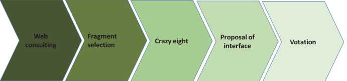
Figure 2 Techniques in PLEC.
It is hard to have an accurate idea of the layout and design of a web page without watching it first. Therefore, first step is to visit web pages (related or not with the vision of the system), searching for inspiration to create the prototypes of the system under development. Some questions that participants could share about a web are:
- Which is the part of the web that you like the most?
- Do you think a web with this design makes your work easier?
After consulting web pages, participants have enough ideas of how they can visually design their LEGO models. To help the design, the participants should copy some parts of the website components that they think may be useful in the design of the GUI.
After having an idea of the components, it is time to design the pages
from the LEGO® models using the components and the crazy eight technique. Each participant folds a sheet in eight parts. Then, in each
part they draw a different version of one page from the LEGO® model using the components obtained from the previous page.
The crazy eight sheets are shared to all members due they could be a source of inspiration for the next technique.
The last technique is to propose a final interface using the inspiration from the crazy eight sheets. A graphical interface is proposed for each
LEGO® model. Every interface has three parts: header, body and footer and each part are drawn in a different piece of paper, so each part may be changed easily.
After that, each LEGO® model have an agreed graphical interface that may be implemented in a tool.
4 Case Study
This section introduces a case study to evaluate the LEGO® SERIOUS PLAY® workshop for creating prototypes of GUI. Papers [11, 12 and 13] exposes the best practices for case studies, which have been also used in the design of the following case study.
4.1 Case Study Definition
First step is defining a clear and valuable research question [12]. This question will define the design of the whole case study including the success criteria [11]. The research question of this case study is announced as a hypothesis. The hypothesis is: LSP can be used to obtain a valuable GUI prototype that satisfies a group of participants (technical and non-technical) in the project.
Several points must be checked in order to validate or discard that hypothesis. Main checkpoints are: it is possible to obtain a GUI prototype after a LSP workshop; participants have a shared definition of what a valuable GUI is, etc.
Reference [12] introduces a list of tasks to design a case study. These tasks are:
- Recruitment.
- Preparation
- Task Design
- Measurement of results
- Exposition of the results and compensations
Briefly, the case study was performed with research and the help of an academic team from the University of Seville (Spain), the system under development was a new iteration of the web learning system that the team already uses.
This is the first time the authors try to perform a LSP workshop for GUI, although the authors have experience applying LSP in other contexts, like the inception of projects, risks identification, etc. This is the reason why authors evaluate that it is too early to involve organizations. One step at each time, short steps in a failsafe environment.
Therefore, we have selected to recruit research members which main goal is to help to discover if the hypothesis is correct. On the occasion of understanding the result, a characterization of the participants is designed. The goal of the characterization is to discover the knowledge of the participant in GUI development and prototyping. The survey used to characterize the participants is in Table 6.
Key aspects for preparing the case study are teaching participants everything they need to know to perform the practical case. One of the main goals of this project, as seen in Section 1, is to allow people from different environments to work together. There is no real need to prepare the participant before the workshop, they just come in, do the warm up activities and they are ready to start working together into the GUI building. Hence, there is no need of any special training on the participants of the case study. However, is needed to instruct the participants, as we will see in the next section.
Next step is task designing where we must create the task of the case study. Due we are not working with a real team in a real project we must provide a context of a system under development, and we have to share this system with the participants so they all have the same goal and scope of the system and they can work together into GUI building. This formation is not necessary in a real context because all participants already know which system they are developing. The workshop design has been discussed in a previous section. Participants do not need to know the design of the workshop and it is a good practice that they could face the questions for first time, so the ideas are fresh and original. Next paragraphs describe the evaluation of the prototyped GUI.
Two measurements are evaluated for evaluating the outcome of the case study: the prototype GUI generated and the insights of the participants of the workshop. Both measurements are evaluated using surveys. The survey for evaluating the prototype is introduced below.
- The duration of the LSP workshop has been adequate • I have actively participated throughout the workshop • My opinions have been taken into consideration throughout the workshop
- The questions that were proposed in the workshop were relevant to the design of the GUI of the system to be developed
• The answers to the questions raised have allowed me to know in detail how the GUI will be developed
- I agree with the results obtained in the workshop After evaluating the measurement of the result, the criteria for determining the success of the use case may be defined. In this case, due the surveys are evaluated in a scale from 1 (strong disagree) to 7 (totally agree), the case study is success if the final result of both surveys is over 5 in a1 to 7 scale.
4.2 Case Study Execution
This section describes the implementation of the case study. Three participants, plus a facilitator, worked in this case study. The description of participants is in Table 5. Next paragraphs describe what happened during the workshop.
First step was to talk about the goal of the workshop. After that, we shared our vision of the system under development, as seen in Figure 3.
White blackboard from Figure 3, at the end of the room has the answer of the questions to check we all share the same vision about the system under development (questions from Table 1). Questions and answers are:
- Which is the goal of the system under development? Managing biological frozen samples.
- Which kind of users are the main target of the app? Embryologist • Which is the main functionality of the web? Store and search for information about the samples
Then, facilitator started the LSP workshop. Participants performed the warm up activities in a previous session, therefore, the work started directly. As seen in a previous section, the first question was to design the main page of the system. The three participants designed different web pages so the final main page was a collage of the three models.
Table 5 Participants
| Name | Role |
| Leticia | Domain expert |
| Virginia | Developer |
| David | Interested |
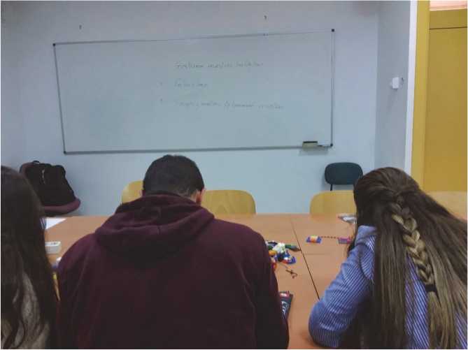
Figure 3 LSP workshop during PLEC process.
After that, facilitator asked the participants to use the LEGO® blocks for building additional pages that embryologist needed to reach their goals. The resulting models were connected among them using additional LEGO pieces. We iterated this question several times, until the participants exposed that the embryologist could reach their goals with the pages built. Then, facilitator asked participants to evaluate the result. Final score was 8’5 over 10 so no need to improvements were detected and the workshop was over. Figure 4 shows the results of the workshop. Post-it notes were added to provide a better description of each page.
After this, we closed this session and booked the second and final session for the next week.
During the second section, the case study group performed the activities described for translating a LEGO® model into a GUI prototype. First activity was web consulting. We searched for relevant websites or those that manage information in a way could be inspiring to create our prototype. Due the system is a model for an existing app, the case study team also reviewed the whole system to capture its graphical style (Figure 5).
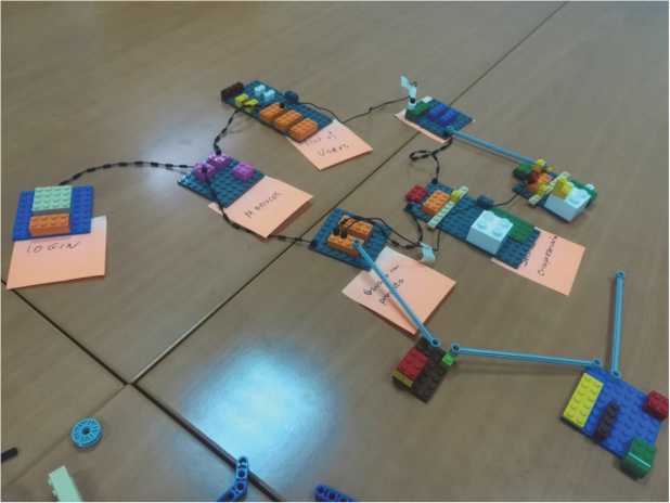
Figure 4 Results of the LSP workshop.
During the web consulting, the case study performed the “web consulting” and “fragment selection” activities. Attenders took notes about web components and layouts to be used in the prototype (Figures 6(a) and 6(b)).
After that, the case study team skipped the “crazy eight” activity because they though they have a clear idea of how the prototype should be. Prototype had to follow the same graphical layout that the web system so no space for crazy ideas. Therefore, the case study team developed their proposals for GUI, then, we voted for the best ideas from the proposals (Figure 6(b)).
Finally, it was time to implement the ideas and the LEGO model into a prototype. Prototype was developed using Microsoft PowerPoint and capturing and editing screens from other sources, as seen in Figure 7.

Figure 5 Web consulting of relevant websites.
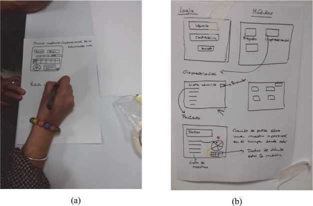
Figure 6 (a) Notes about web components and (b) proposals on the wall.

Figure 7 Final prototype using MS PowerPoint.
Table 6 Survey results
| Question | Mean | Median |
| The duration of the LSP workshop has been adequate | 5,5816 | 6 |
| I have actively participated throughout the workshop | 6,4807 | 6,5 |
| My opinions have been taken into consideration throughout the workshop | 5,7660 | 5,5 |
| The questions that were proposed in the workshop were relevant to the design of the GUI of the system to be developed | 5,2772 | 5,5 |
| I agree with the results obtained in the workshop | 5,5555 | 5,5 |
| The answers to the questions raised have allowed me to know in detail how the GUI will be developed | 4,9660 | 5 |
Prototype was created after the last session, hence the evaluation of the prototype was conducted by email. Participants received an online form with the survey. This form was introduced in a previous section. Results are introduced in Table 6. Answers are rated from 1 (totally disagree) to (7 totally agree).
No generalizations could be done due to the limited results. However, participants told us in the survey that they found value applying PLEC for prototyping the new module.
5 Conclusions
This paper has described PLEC process. PLEC has three main elements: a LEGO ® SERIOUS PLAY® workshop for creating a conceptual GUI with the support of all participants, a set of dynamics for translating the GUI components into graphical components and the implementation of the interface in a GUI prototype. PLEC remarks the teamwork where everyone collaborates in the solution. The final GUI should have elements from all participants in a constructive way.
In the case of study, we have had a person with a deep knowledge in the application and mastery of the problem, but the person who was going to develop the GUI and the rest of the system did not have that knowledge. After using PLEC, they have been able to have a shared vision and, in addition, they have developed together the interface prototype that captures the knowledge of the domain of the problem.
Based on the experience of the authors implementing LSPin general and in the specific case of PLEC, we found two main problems. First one is the time needed to perform a LSP workshop. Usually a workshop consumes a whole day or at least half a day. This time is necessary to deepen the questions raised and reach consensus. All participants must be focused in the workshop for the whole duration of it. However, this time is not always available in the development of information systems.
The second problem is the necessity to have a facilitator to help running the LSP workshop and the GUI creation activities. A facilitator needs knowledge and experience implementing LSP and it is not advisable that someone without experience tries to do it since it jeopardise the results of the workshop and it is possible that the participants take a bad impression of LSP.
Future work is developing more case studies with different participants, organizations, projects and technologies for building GUI prototypes. For examples, we plan to apply our proposal for the design and development of technological solutions in the area of requirements engineering [14, 15], software process management [16]. Entity Identity Reconciliation based Big Data [17] and clinical process management [18].
Acknowledgments
This paper have been supported by the Spanish foundation HERGAR and their call “Convocatoria de Ayudas a Proyectos I+D+i 2017”.
References
[1] Potts, C., Takahashi, K. and Anton, A.I. (1994) Inquiry-Based Requirements Analysis, IEEE Software, Vol. 11, Issue 2, pp. 21–32.
[2] Kristiansen, P., and Rasmussen, R., “Building a Better Business Using the Lego Serious Play Method: The Lego Serious Play Method”. John Wiley & Sons Inc. USA. (2014).
[3] F. Kifetew, D. Munante, A. Perini, A. Susi, A. Siena, and P. Busetta, “DMGame: A Gamified Collaborative Requirements Prioritisation Tool,” Proc. – 2017 IEEE 25th Int. Requir. Eng. Conf. RE 2017, pp. 468–469, 2017.
[4] Cantoni, L., Faré, M., and Frick, E., “User Requirements with Lego.”. https://d3gxp3iknbs7bs.cloudfront.net/attachments/c6a2c c2e83a9849916a88ffc6548b6736cc51250.pdf
[5] Kurkovsky, S., “Teaching Software Engineering with LEGO Serious Play,” Proc. 2015 ACM Conf. Innov. Technol. Comput. Sci. Educ. – ITiCSE ’15, pp. 213–218, 2015.
[6] Pettersson, J. S., and Andersson, H. (2017). Wizards of Oz in the Evolving Map of Design Research – Trying to Frame GUI Interaction Interviews Supporting Development of Interactive Systems in Interactive Sessions. HUMAN COMPUTER INTERACTION IN ISD.
[7] Moore, J. M., and Texas, A. (2003). Communicating Requirements Using End-User GUI Constructions with Argumentation. 18th IEEE International Conference on Automated Software Engineering, 1527–1366.
[8] Lizcano, D., Soriano, J., López, G., and Gutiérrez, J. J. (2017). Automatic verification and validation wizard in web-centred end-user software engineering. Journal of 9-Systems and Software, 125. https://doi.org/10.1016/j.jss.2016.11.025
[9] Lizcano, D., Alonso, F., Soriano, J., and López, G. (2016). Web-centred end-user component modelling. Future Generation Computer Systems, 54, 16–40. https://doi.org/10.1016/j.future. 2015.07.002
[10] Knapp J., Zeratsky J., and Kowitz B. Sprint. Transworld Editions. 2016
[11] Mohagheghi, P. (2010). An Approach for Empirical Evaluation of Model-Driven Engineering in Multiple Dimensions. From Code Centric to Model Centric: Evaluation the Effectiveness of MDD (C2M:EEMDD), (2006). https://doi.org/10.1007/s11205-011-9933-3
[12] Ko, A. J., LaToza, T. D., and Burnett, M. M. (2013). A practical guide to controlled experiments of software engineering tools with human participants. Empirical Software Engineering, 20(1), 110–141. https://doi.org/10.1007/s10664-013-9279-3
[13] Madeyski, L., and Kawalerowicz, M. (2017). Software Engineering: Challenges and Solutions, 504, 1–13. https://doi.org/10.1007/978-3-319-43606-7
[14] García-García, J. A., Escalona, M. J., Ravel, E., Rossi, G., and Urbieta, M. (2012, December). NDT-merge: a future tool for conciliating software requirements in MDE environments. In Proceedings of the 14th International Conference on Information Integration and Web-based Applications & Services (pp. 177–186). ACM.
[15] Escalona, M. J., Urbieta, M., Rossi, G., García-García, J. A., and Luna, E. R. (2013). Detecting Web requirements conflicts and inconsistencies under a model-based perspective. Journal of Systems and Software, 86(12), 3024–3038.
[16] García-García, J. A., Meidan, A., Carreño, A. V., and Risoto, M. M. (2017, October). A Model-Driven Proposal to Execute and Orchestrate Processes: PLM4BS. In International Conference on Software Process Improvement and Capability Determination (pp. 211–225). Springer, Cham.
[17] Enríquez, J. G., Domínguez-Mayo, F. J., Escalona, M. J., García-García, J. A., Lee, V., and Goto, M. (2015). Entity Identity Reconciliation based Big Data Federation-A MDE approach.
[18] García-García, J. A., Escalona, M. J., Martínez-García, A., Parra, C., and Wojdyński, T. (2015). Clinical process management: a model-driven & tool-based proposal.
Biographies

Javier J. Gutiérrez received his B.S. degree in Computer Science from University of Sevilla, Spain, in 2001. Since April 2003 he has been teaching and researching in the same University. He received the Ph.D. in Languages and Computer Science in 2011. He is currently researching about testing and model driven development. His research interests include combining techniques and tools with formal methods and improving agile solutions.

Carlos Arévalo PhD and MEng in Industrial Engineer at the University of Seville. He is a lecturer at the Department of Languages and Information Systems of the University of Seville. He has more than thirty years of experience in large software projects with private and public companies, as developer, analyst and senior consultant. He has worked in complex projects with tailor-made and ERP systems. His research areas include databases, software engineering and business process modeling. My research work concerns to reverse engineering Legacy Information Systems. It covers approaches to include time and resource perspectives in business processes.
David Lizcano holds a Ph.D. in Computer Science (2010) and a M.Sc. in Research in Complex Software Development (2008) from the Universidad Politécnica de Madrid, UP. He is Professor at Madrid Open University, UDIMA. He held a research grant from the European Social Fund, and was involved in several national and European-funded projects relating to service-oriented architectures, programming paradigms, software engineering, human-computer interaction and end-user development. He has published his research in more than 30 high-ranking JCR-indexed journals.