Verification of the Instantiation and Integration of Security Patterns
Tu Peng1,*, Shuliang Wang1, Jing Geng1, Qinsi Wang2, Yun Yang3 and Kang Zhang4
1School of Computer Science and Technology, Beijing Institute of Technology, Beijing, 100081, China
2Department of Computer Science, Carnegie Mellon University, Pittsburgh, USA
3School of Software and Electrical Engineering, Swinburne University of Technology, PO Box 218, Hawthorn, Melbourne, Australia 3122
4Department of Computer Science, University of Texas at Dallas, Richardson, TX 75083, USA
E-mail: pengtu@bit.edu.cn; slwang2011@bit.edu.cn; janegeng@bit.edu.cn; qinsiw@ cs.cmu.edu; yyang@swin.edu.au; kzhang@utdallas.edu
* Corresponding Author
Received 26 May 2020; Accepted 02 June 2020; Publication 14 August 2020
Abstract
As software applications suffer from increasing malicious attacks, security becomes a critically important issue for software development. To avoid security problems and increase efficiency, a large software system design may reuse good security solutions for existing security patterns. While security patterns document expert solutions to common security problems and capture well-examined practices on secure software design, implementing them in a particular context (pattern instantiation) and composing them with other related patterns (pattern integration) are prone to flaws and may break expected security properties. In this paper, we present an approach to verify security patterns instantiation and integration automatically. We offer formal definitions for security pattern instantiation and integration, and establish rules to transform sequence diagrams (representing the behaviors of security patterns) to expressions in Milner’s Calculus of Communicating Systems (CCS). We prove the correctness of the proposed transformation, and propose an algorithm to carry out this transformation automatically. In particular, we formally specify the alternative flows of UML sequence diagrams guarded by constraint conditions, which allows us to model choice making behaviors of security patterns precisely. The properties of the instantiation and integration can be verified by model checking against their CCS expressions. Flaws of instantiation and integration can, therefore, be discovered early in the design stage. We use two case studies to illustrate our approach and show the capability to prove security in integration and detect design errors in instantiation respectively.
Keywords: Software engineering; software safety; software verification.
1 Introduction
With increasing security attacks, security becomes a critical requirement for the successful software system development. Studies (e.g. [29]) have shown that design flaws and errors are commonly the main sources of security loopholes that can be taken advantage of by attackers. Therefore, safe software architecture and design are at the heart of software security. Security patterns [27] document good practices to solve security problems arising frequently in software development, and encourage reusing expert solutions. A security pattern is a recipe for solving a particular security problem. It is a design pattern [12] that generally describes a group of participants as well as their relationships and collaborations, which achieve some security goals. Each participant in a group is defined generically in terms of the role that it plays in the security pattern. The participants’ relationships are normally described in UML class diagrams and their collaborative behaviors are described in sequence diagrams. The benefits of defining security patterns include (1) allowing the reuse of security design, and (2) documenting expert design experience, security design tradeoffs, and security decisions, so as to improve communication.
To use a security pattern in a particular application, one needs to instantiate it with the application domain information. This instantiation process may change the generic names of the participating classes into ones reflecting the application. It may also change the number of the participating classes in some prescribed way. Meanwhile, multiple security patterns can be integrated into large software systems to solve compound security problems. Integrating security patterns may help to reuse expert solutions to different security problems in the same system. Such integration may happen before or after the pattern instantiation process. While each security pattern is forced to respect some security laws, the integration of these security patterns will sometimes break them. That is, since the patterns instantiation and integration involve changing both structures and behaviors of generic security patterns intensively, there can be inconsistencies among the instantiation and integration such that some critical security properties may no longer hold. The inconsistencies may cause problems in the design. It is important to discover these problems and errors early in the design stage, as such design errors are very difficult to find and correct once they are transformed to implementation errors. Analysis techniques that help to find such design errors are crucial to the quality of the software systems. It is cost effective to prevent coding problems in advance than to discover them later by testing. Although we can translate diagrams into codes and make proofs in terms of codes, it is simply slower and more expensive to do so. On the other hand, mistakes may be introduced when translating sequence diagrams into codes. Moreover, software design elements and design-level behaviors are originally represented by UML sequence diagrams instead of codes. Thus, applying formal verification against UML sequence diagrams is comparatively straightforward. Security pattern instantiation and integration are design-level behaviors that are originally represented by UML diagrams. Hence it is reasonable to build our approaches on verification of UML sequence diagrams.
For the past decades, noticeable achievements [14, 15, 18, 30, 31] have been made on specification and verification of UML sequence diagrams. H. Storrle [24] studied the semantics of UML sequence diagrams with a focus on formalizing the semantics of sequence diagrams using set theory rigorously. Kong et al. used graphic grammar to describe the behaviors of UML diagrams including sequence diagrams, and demonstrated the ability to facilitate the verification of design models against system requirements [15]. Li studied on rigorous formal semantics for UML sequence diagram [17]. In details, the structural information of sequence diagram was defined by set theory: the message was defined as a tuple of source object, target object, action and order; and behavioral information was defined by communicating sequential processes (CSP). Based on formal specification of a sequence diagram, other work employed verification techniques. Automatic verification of security pattern composition by model checking sequence diagrams was discussed in [4, 5]. Model checking UML sequence diagram by SPIN was presented in [18]. A translator was implemented to automatically generate system specifications for model checking. PROMELA [13] was used for system specifications and Linear Temporal Logic (LTL) was used for properties specification in model checker SPIN [13].
These previous work have demonstrated the significance and presented methodologies of formal specification and verification of UML diagrams, which leads to the work in our paper. However, these approaches do not aim at exploring an automatable way of specifying the behaviors of security patterns, particularly their instantiation and integration. Meanwhile, existing approaches do not provide ways to set the values of the constraint conditions (so that choice can be made) and verify each possible flow of alternative flows, which are critical behaviors of security patterns.
In this paper, we propose an automatable (maybe you want to say “automatic”?) way in specifying and verifying the instantiation and integration of security patterns. We formally define the security pattern instantiation and integration processes, and provide an automatable way of specifying the instantiation and integration with CCS [22]. In addition, we offer two methods to specify sequence diagrams with multiple alternative flows. One method specifies all reachable branches of a sequence diagram; the other specifies some particular branches guarded by the constraint conditions we are interested in. The designer can choose between these two methods to gain a complete system model with all state transitions or a trimmed model with fewer state transitions for model checking. We prove that the CCS specifications truthfully represent synchronous messages, asynchronous messages, and alternative flows of a UML sequence diagram. Model checking is used to verify whether the critical properties are held in security patterns instantiation and integration. The analysis results show that our approach is able to improve the design reliability leading to secure software, and detect design errors that may cause security flaws.
The remainder of this paper is organized as follows. The next section describes our analysis techniques with respect to security patterns instantiation and integration. Section 3 presents a case study to illustrate our approach and show the discovery of several subtle security problems in security patterns instantiation involving multiple alternative flows behaviors. Another case study is given in Section 4 to show the verification of security pattern integration involving multiple alternative flows behaviors. The last two sections cover related work and conclusions.
2 Related Work
Existing work on security patterns is typically on the introduction of new security patterns or the applications of security patterns in different systems. Steel et al. presented a comprehensive study on the reoccurred security patterns in Java programming [27]. They recorded the intent, motivation, problem context, structures and behaviors of each security pattern. Microsoft published design solutions for problems reoccurred in web security applications [33]. Those security patterns concentrate on authentication, secure message transmission and access control in web service. Rosado et al. provided a template to describe security patterns and a framework to compare them in [22]. Several security patterns are presented in their template. They also measure the security degree of the patterns and indicate the level that each pattern fulfills the properties and attributes common to all security patterns. No discussion of the security pattern integration is presented. To develop secure and efficient distributed systems, Yoshioka et al. [25] propose a method that uses patterns with security taken into account. They model the performance data associated with each pattern and provide the selection procedures for the detailed specifications. Their approach includes a pattern library that consists of several security patterns for inter-company coordination systems. Their patterns are applied in the environmentally conscious product design support system. However, their work does not formally analyze the integration of the security patterns. Yoshioka et al. [26] introduce 29 security patterns and classify them into either structural or procedural patterns. Structural patterns can be implemented in an application whereas procedural patterns aim at improving the development process of security-critical software systems. Brown et al. [3] propose authenticator, a security pattern, to describe a general mechanism for providing identification and authentication to a server from a client. While these works introduce a number of security patterns, the analysis of security patterns instantiation and integration is not in their scopes.
A study on model checking security pattern has been presented by Dong [5–7]. It introduces a way to specify security pattern composition in CCS and practice automatic verification of the sequence diagram against properties in GCTL scripts by model checking. Although their specification methods also use CCS as the specification algebra for sequence diagrams, it lacks the following innovation aspects that are presented in this paper: (1) It does not consider the verification of alternative flows. In most conditions, the behavior of security pattern involves making choice according to certain constraints. For example, we need to check password (constraints) in Authentication Broker pattern, and balance amount in Safe Withdraw pattern. In those cases, security patterns will behave in one way if constraints are satisfied and another way otherwise. Making choice is a critical behaviour of security pattern, but in [5, 8], it lacks specification and verification of it. In this paper, we provide specification rules and verification rules (Theorem 4, Theorem 7, Lemma 8) for choice-making behaviour (alternative flows). Moreover, we provide a way of setting choices to our best interests. (2) It does not formally define design pattern instantiation and integration, while we present formal definitions for design pattern instantiation and integration. (3) It does not show communicating messages, that is, the communicating messages are specified as internal messages that do not subject to model checking. For example, we cannot check the existence of a within P = (a|′a)\{a}, because P shows no action that can be observed (P has an empty set of traces). In this paper, we use a different approach. By introducing communicating channels, we are able to check the existence of a within P = (a.Channela|′Channela)\{Channela}. Communicating messages contribute to a large portion of the message invocations of security pattern behaviours, thus important for the verification.
A way of model checking for UML sequence diagram (with alternative flows) by SPIN is presented in [18]. The destination and source of messages (send/receive events) is modeled as send and receive operations of PROMELA elements. A translator software is implemented to automatically generate system specification [18]. The verification is conducted by model checking: the PROMELA [13] scripts and LTL (Linear Temporal Logic) properties are sent to model checker SPIN [13], which then tells whether the properties are satisfied. The alternative flows are randomly chosen by SPIN before execution of the PROMELA script. It does not provide techniques to control the values of the constraint conditions. Meanwhile, analysis of security patterns instantiation and integration is not mentioned.
A UML profile (UMLSec) on security has been introduced in [16], which can help to model security-related concerns in UML diagrams. Formal semantics have also been provided for a subset of each kind of UML diagrams. In particular, the behavioral semantics of a simplified fragment of UML sequence diagram was presented. However, it cannot specify alternative flows, which is common in a sequence diagram. Model checking has been applied to check the security properties, such as secrecy, integrity, authenticity, and refinement, against the UMLSec specifications. The application of a security pattern was also discussed. In contrast, our work focuses on security pattern compositions rather than just the application of a single security pattern. In addition, we analyze the compositions of security patterns with model checking techniques, instead of general security properties checking in UMLSec specifications. Furthermore, our behavioral semantics of sequence diagram can specify alternative flows. It can only specify sequential behaviors.
Many works have addressed the necessity of formal verification on sequence diagrams [16, 28, 29]. Other works have provided tools for verifying UML diagrams [11, 16]. The semantics of UML sequence diagrams has been studied by Storrle [24]. The interaction traces of UML sequence diagrams are defined as a sequence of event occurrences, which are triples of Lifelines, Actions, and Timepoints. The alternative flows are defined as the union of two interaction fragments. Storrle’s work focuses on formalizing the semantics of sequence diagrams using set theory rigorously. Other researchers also investigate the specification of UML sequence diagrams. A sequence diagram has been specified as an Event Deterministic Finite Automat (EDFA) [30], which captures the state transitions of the objects interacting in the sequence diagram. In addition, automatic verification of sequence diagrams by model checking for EDFA is provided. B method [1] has been used for specification and verification of UML sequence diagrams in industry. It uses predicate logic, preconditions and postconditions to define the properties respected by method invocations in a sequence diagram.
The structural and behavioral aspects of design patterns in terms of responsibilities and rewards are formally specified in [Soundarajan and Hallstrom 2004]. Following the ideas of the design by contract approach in [21], the structural and behavioral specifications are captured as responsibilities, whereas the rewards capture the benefits of applying the pattern with the expected behavior in a system. The composition of two design patterns based on a specification language (DisCo) has been discussed in [19]. The behavior of each pattern is formalized as a layer in DisCo. The composition of design patterns is defined as a refinement on the layers of specifications. Formal specification of design patterns and their composition based on the Language of Temporal Ordering Specification (LOTOS) is proposed in [23]. In particular, the behavioral aspect of the Command and Composite patterns and their combination is specified. Property patterns [9] have been proposed to provide taxonomy of properties written in LTL, CTL and QRE. Each property pattern is defined in terms of its scope, which is the extent of the program execution over which the pattern should hold. Property patterns define general properties whereas we focus on security-related properties. This research is intended for formal specification and verification of general design patterns behaviors and structures. It leads us to the research on verification of security patterns instantiation and integration.
3 Security Analysis
Many security patterns have been identified to solve the recurring security problems, such as authentication, authorization, confidentiality and integrity during communication. Unsecured communications are often exposed to eavesdropping, spoofing, sniffer, and replay attacks. In detail, confidentiality means that communication cannot be eavesdropped by a malicious third party. The replay attacks copy the legitimate transactions and resend them. The sniffer attacks just capture sensitive information for later use. Integrity means that changing, copying, or resending legitimate transactions cannot cheat legal parties in the communication. Integrity is essential to exclude man-in-the-middle attacks that harm not only the unsecured network but also VPN where data is exposed at the end points. This exposed data is subject to disclosure, modification, or duplication. Some of these attacks are easy to be carried out, even for novices. As a consequence, these attacks may result in huge losses for businesses that need to communicate sensitive data.
In this section, we introduce a motivating example followed by model checking techniques. We then introduce our approach to modeling the behavior of a security pattern, which may then be checked by a model checker. We describe a general way to specify the instantiation and integration of security patterns in CCS and prove the correctness of the transformation from sequence diagrams of a security pattern to our specification. In particular, we describe the way to specify security patterns with alternative flows guarded by constraint conditions.
3.1 Motivating Example
Software verification is indispensable in the development of reliable software. By proving certain design properties (e.g. safety and liveness properties), the correctness of a design model can be assured. Otherwise, design mistakes will be carried into the programming stage, and cause software malfunctions that may hardly be discovered by testing. It is cost effective to prevent coding problems in advance than to discover them later by testing. Although we can translate diagrams into code and make proofs in terms of code correctness, it is often slower and more expensive to do so. As a motivating example, a simple sequence diagram depicting the behaviors of a security pattern is shown in Figure 1. In this sequence diagram, a directed edge depicts a method invocation. Expected call sequences are also shown. A call sequence depicts an expected design property, and it is important to ensure the sequence diagram satisfying it. If a call sequence can be matched with the exact order in all branches of the sequence diagram, we say it is satisfied in all paths. If a call sequence can be matched with the exact order in at least one branch, we say it is satisfied in at least one path. If a call sequence has no exact match, we say it is missed. In our approach, we will propose a formal model for a sequence diagram and the expected properties. In addition, we will propose searching algorithms suitable for property verification by model checking.

Figure 1 Motivating example.
3.2 Model Checking
Model checking is a widely used technique for automatic verification of software. A model checker automatically verifies the consistency between system and properties. System and properties need to be specified in certain languages required by a chosen model checker. In order to analyze the integration of security design patterns, we apply model checking techniques. In our case, we assume a logic model representing the security patterns and their integration, as well as a logic formula representing a property to hold. In order to determine whether a pattern-based system satisfies the properties, it is checked whether the formula holds in the logic model of security pattern integration or instantiation.
There are several model checking tools, such as SMV [18], SPIN [15], XMC [21], and CWB-NC [2]. In this paper, we will concentrate on the CWB-NC model checker since we can use it to specify security patterns in process algebra and analyze their instantiation and integration by model checking. CWB-NC requires the user to specify the systems in CCS and the temporal properties with GCTL [20] (extension of computational tree logic, CTL [10]). It will then check whether the system satisfies the properties. With model checking, we are able to verify the security pattern instantiation and instantiation.
The syntax of CCS is as follows: a CCS formula F defines a process in communication. F is an expression of actions joined with CCS operators. An action name is a user-defined id, which represents a system activity. The prime symbol “′”, which is placed in front of an action name, denotes that this action is an output of the system. The operations between actions include sequential composition “.”, non-deterministic choice “+”, parallel (concurrent) composition “|”, and restriction “\”. A restriction is used together with the parallel composition, to denote that the messages being restricted are internal messages. For example, P = (P1|P2)\L defines a process P that is the parallel composition of process P1, P2. L defines a set of channels used by P1 and P2. L actually forces a synchronization between parallel composition P1 and P2. To gain better understanding, suppose P1 = a.b, P2 = ′b.c, L = {b} where a, b, c are actions. Then (P1|P2)\L = a.c.
3.3 Approach Overview
The behavior of a security pattern is normally described using a UML sequence diagram. By modeling sequence diagram in CCS specification, we obtain the formal model of security pattern. Multiple formal models can be integrated using CCS concurrent composition, which naturally models security pattern in integration.
Figure 2 illustrates our approach to analyze security pattern instantiation and integration. The generic security pattern specifications capture good design practice in a domain-independent way. These declarative representations, which constitute the models of the security patterns, are then instantiated into concrete domain-specific representations. In this way, security design can be reused practically. In addition, the instances of security patterns can be composed to form an integration of security patterns. To verify the integration or instantiation of security patterns, one needs to transform the integration or instance to a model M of CCS, which is then submitted to a model checker. We use the model checker to check M against the property specification P. The model checker outputs either true if M satisfies P, or a counterexample if it does not.
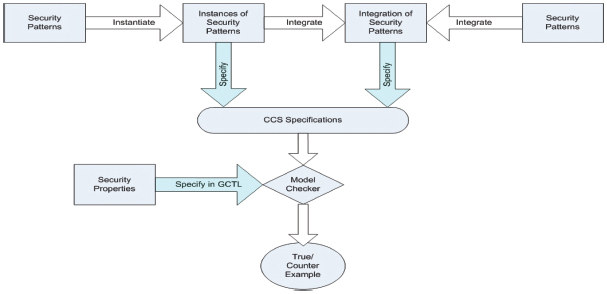
Figure 2 Overview of our approach.
The sequence diagram of security pattern is specified as the concurrent composition of the participating objects interacting with each other. Each object in the security pattern is modeled as a CCS process that inputs some messages to the input channel, performs actions, and outputs some messages to the output channel. A message represents a method/operation. An object can send messages out to or receive messages from other objects. The message that is being sent to the receiving object represents an operation/method that the receiving object’s class implements. For example, Object1 receives message B and sends message D, E, and F to Object2 in Figure 1. In this case, CCS specifications of Object1 and Object2 are: Object1:=B.′ChD. ′ChE.ChF and Object2:=ChD.D.ChE.E.ChF.F The CCS specifications of them are: Object1|Object2=B.′ChD.′ChE.ChF|ChD.D.ChE.E.ChF.F=B.D.E.F, which is obtained by applying Milner’s Expansion Law [22]. Furthermore, we can obtain the CCS specifications of the sequence diagram in Figure 1 as Object1|Object2|Object3|Object4|Object5, which can be model checked.
3.4 Formal Specifications
The following rules are introduced to model a basic UML sequence diagram (without alternative flows) with CCS specifications. Intuitively, we model a UML object as a CCS process. The message passing (function invocation) between objects are modeled as CCS concurrent composition. We will then propose a way of modeling complex UML sequence diagram with alternative flows. We will also prove the correctness of the CCS specifications.
Definition 1 (CCS Specification Rules). Let X be the sequence diagram, C be the object set of X, and M be the message set of C. The rules to transform S to CCS specifications (CCS(X)) are:
(1) For each object i ∈ C only consists of sequential control flow (e.g., no alternative flows and loops), its CCS specification (CCS(i)) is the sequential composition of its message invocations by CCS operation ‘.’, in order of their temporal occurrences. That is, CCS(i) = m1.m2. .... mk. Object i can carry its class name if needed, i.e., i = class-name_objectname. Message m can carry its implementation class name if needed, i.e., m = classname_messagename.
(2) An input message is specified as a sequential composition of a Channel name and the message name. Suppose object i receives message m, then CCS(i) = CHm.m, where CHm is the channel of receiving m, CCS(i) represents that class of i implements method m.
(3) An output message is the Channel name prefixed with ‘′’. Suppose class i sends out message m, then CCS(i) = ′CHm. CCS(i) represents an object that i calls method m.
(4) For each m ∈ M, m = m1.m2, where m1 is message name and m2 is its signature.
(5) For a class i ∈ C with alternative flows, its CCS specification is the alternative composition of its sequential flows.
(6) The specification of S is given by CCS(X) = Πi∈C CCS(i)\L, where L is the set of all message channels, CCS(i) is the CCS specification of object i. Πi∈C(i) = CCS(c1)j ... jCCS(i)j ... is the concurrent composition of CCS(i), i ∈ C.
Definition 1 provides an algorithm to automatically specify complicate behaviors of security patterns consisting of multiple objects and multiple control flows, which is hard to specify by human hands otherwise. To prove that CCS(X) is semantically equivalent to the sequence diagrams which represent the behaviors of the security pattern, we continue to show that the synchronous messages, asynchronous messages, and alternative flows of a sequence diagram are faithfully transformed by Definition 1.
3.5 Synchronous and Asynchronous Messages Specification
In synchronous message passing scenario, the Message Caller (object a) sends out a synchronous message and waits for the return before continuing, which is shown in Figure 3 on the left. We use two messages, m and r, to represent the synchronous message and the corresponding return message, respectively. We use message p1 to represent any action that happens before the synchronous message and message p2 to represent any action happens after the return message. Message q represents any action performed by object b before returning message r. While this synchronous property can be observed intuitively in the sequence diagram, it is not clear whether the derived CCS preserves it. That is, whether CCS(X) semantically indicates the synchronous property that action p2 can only be invoked immediately after receiving r.
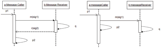
Figure 3 Synchronous message and asynchronous message.
Lemma 2 Let Syn be the sequence diagram containing object a (message caller) and object b (message receiver). Let m be the synchronous message from a to b. Let r be the return message. According to Definition 1, the specification of sequence diagram Syn is CCS(Syn) = P(a)|P(b)\L, where P(a) = p1.′CHm.CHr.r.p2, P(b) = CHm.m. q.′CHr, and L = {CHm, CHr}. It is provable that CCS(Syn) r.p2, which semantically indicates that p2 can only be invoked immediately after receiving r (synchronous property).
Proof. CCS(Syn) = p1. ′CHm.CHr.r.p2|CHm.m.q.′CHr\{CHm, CHr}.
According to the Milner’s Expansion Law, p1 is not restricted by L. Thus, it can be taken out of the concurrent operation. Hence we have
CCS(Syn) = p1.(′CHm.CHr.r.p2|CHm.m.q.′CHr)\{CHm, CHr}.
Based on Expansion Law, ′CHm and CHm communicate with each other and can be merged to t, we have
CCS(Syn) = p1.t. (CHr.r.p2|m.q.′CHr)\{CHm, CHr}.
Since m and q are not restricted by L, it can be taken out of the concurrent operation. Hence we have
CCS(Syn) = p1.t.m.q.(CHr.r.p2|′CHr)\{CHm, CHr}.
Based on Expansion Law, ′CHr and CHr communicate with each other and can be merged to t, we have
CCS(Syn) = p1.t.m.q.t.(r.p2)\L.
Since r and p2 are not in L, we omit L
CCS(Syn) = p1.t.m.q.t.r.p2.
That is CCS(Syn) r.p2, where α = p1.t.m.q.t.
That completes the proof.
Different from a synchronous message, a message is asynchronous when the Message Caller can send or receive other messages without waiting for the return message. In this situation, asynchronous property means that object a can send message p2 right after sending out message m. Message q and message p2 may be invoked in any order. It may be possible for p2 to happen before q, and also possible for q to happen before p2. In other words, the asynchronous property allows either order of their occurrences. We have proved that CCS(Asyn) semantically indicates the asynchronous property.
Lemma 3 Let Asyn be the sequence diagram containing object a (message caller) and object b (message receiver) as in Figure 3 on the right. Let m be the asynchronous message from a to b. According to Definition 1, the specification of sequence diagram is CCS(Asyn) = P(a)|P(b)\L, where P(a) = p1.′CHm.p2, P(b) = CHm.m.q, and L = {CHm, CHr}. It is provable that CCS(Asyn) → p2.q + q.p2, which semantically indicates that action p2 and q can happen in any order (asynchronous property).
Proof. It is similar to previous proof.
3.6 Alternative Flows Specification
The behaviors of most security patterns include alternative flows that designate a mutually exclusive choice between two or more message sequences. In order to model check behaviors of security patterns with alternative flows, we need to model sequence diagrams with alternative flows in CCS. Sequence diagram Xalt with alternative flows is shown in Figure 4, where message a will be sent by Object1 if the condition is satisfied. Otherwise, message b will be sent. We will not consider the runtime value of the condition. In other words, our focus is on specifying control flows statically. The following theorem specifies sequence diagram with alternative flows in CCS. It also proves the CCS specifications semantically indicate the alternative behaviors of the sequence diagram with alternative flows.
Theorem 4 Let CCS(Xalt) be the specification of sequence diagram Xalt with alternative flows: if [condition] of Object1 is true, then message a is sent; if the condition is not true, then message b is sent. Action A1 and action B1 present actions before and after the alternative flow segment of Object1. Action A2 and action B2 present actions before and after the alternative flow segment of Object2. Then
CCS(Xalt) = A1.(condTRUE. ′CHa + condFALSE.′CHb).B1|
A2.(CHa.a + CHb.b).B2)\{CHa, CHb}.
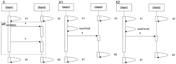
Figure 4 Alternative flows.
It is provable that CCS(Xalt) = CCS(X1) + CCS(X2), which semantically indicates the alternative flows property: if the constraint is satisfied, CCS(Xalt) behaves as sequence diagram X1. If not, CCS(Xalt) behaves as sequence diagram X2.
Proof. Let L = {CHa, CHb}. Distributing operator ‘+’ out of ‘.’, we have:
CCS(Xalt) = (A1.condTRUE. ′CHa.B1 + A1.condFALSE. ′CHb.B1)
|(A2.CHa.a.B2 + A2.CHb.b.B2)\L.
Distributing ‘+’ out of ‘|’, we have
CCS(Xalt) = T1 + T2 + T3 + T4,
where
T1 = (A1.condTRUE.′CHa.B1|A2.CHa.a.B2)\L,
T2 = (A1.condFALSE.′CHb.B1|A2.CHa.a.B2)\L,
T3 = (A1.condTRUE.′CHa.B1|A2.CHb.b.B2)\L,
T4 = (A1.condFALSE.′CHb.B1|A2.CHb.b.B2)\L.
By Milner’s Expansion Law, condTRUE, A1 and A2 are not restricted and can be taken out of the concurrent operation:
T1 = (A1.condTRUE|A2).(′CHa.B1|CHa.a.B2)\L.
By Milner’s Expansion Law, ′CHa and CHa communicate each other and can be merged to empty action t:
T1 = (A1.condTRUE|A2).t.(B1|a.B2).
By Definition 1,
CCS(X1) = (A1.condTRUE|A2).t.(B1|a.B2).
Hence
T1 = CCS(X1).
By Milner’s Expansion Law, A1, condFALSE, and A2 are not restricted and can be taken out of the concurrent operation:
T2 = (A1.condFALSE|A2). (′CHb.B1|CHa.a.B2)\L.
Since ′CHb and CHa cannot communicate each other and are restricted, the term ′CHb.B1|CHa.a.B2\L has no transitions, which is trace-equivalent to stop action nil:
T2 = (A1.condFALSE|A2).nil.
By Milner’s Expansion Law, A1, condTRUE and A2 are not restricted and can be taken out of the concurrent operation:
T3 = (A1.condTRUE|A2).(′CHa.B1|CHb.b.B2)\L
= (A1.condTRUE|A2).nil.
Similarly:
T4 = (A1.condFALSE|A2).t.(B1|b.B2).
By Definition 1,
CCS(X2) = (A1.condFALSE|A2).t.(B1|b.B2) = T4.
Since T1 includes all transitions of T2 we have T1 + T2 = T1. Since T4 includes all transitions of T3 we have T3 + T4 = T4. Therefore
CCS(Xalt) = T1 + T2 + T3 + T4 = T1 + T4 = CCS(X1) + CCS(X2).
That completes the proof.
Since CCS(Xalt) proposed by Theorem 4 is the system model of sequence diagram Xalt, we can apply model checking on CCS(Xalt) to verify the behaviors of any design pattern presented by Xalt. By adding condTRUE and condFALSE as tag actions (actions not involved in the state transitions of sequence diagram X) in the CCS model, we are able to verify system properties when constraint condition is satisfied (by adding tag condTRUE in the GCTL formula) or not satisfied (by adding tag condFALSE in the GCTL formula). It is important to notice that we use CCS(Xalt) as the system formula in model checking instead of CCS(X1) + CCS(X2) because of the problem of formula length. If we simply specify the sequence diagram with n alternative flows as CCS(Xi), we will have a CCS specification whose length is too long for a model checker. To be more specific, CCS(X1) + CCS(X2) is twice as long as CCS(Xalt) when sequence diagram has 1 alternative flow. CCS(Xi) is 2n times as long as CCS(Xalt) when sequence diagram has n alternative flows.
4 Security Patterns Instantiation Verification
To use a design pattern in a particular application, one needs to instantiate it with the application domain information. This instantiation process may change the generic names of the participating classes into those reflecting the application. It may also change the number of the participating classes in some prescribed way.
Definition 5 (Design Pattern Instantiation). Let X < C, R, M, N > be the behavior description of a design pattern, where N is the namespace including all the class names and method names. C is the set of classes in X with C ⊂ N. R = {(f, g, r)|f ∈ C, g ∈ C, r ∈ {inheritance, association}} denotes the relationship of classes in C. M = {(m, s, e) |m ∈ N, s ∈ C, e ∈ C}, where s is the caller class (class that starts the call), e is the called class (class that implements the method called), and m is the method name. The instance of X is given by X′ < C′, R′, M′, N′ >, where N′ is the namespace including all the class names and method names of X′. C′ is the set of classes in X′ with C′ ⊂ N′. M′={(m, s, e) |m∈N′, s ∈ C′, e ∈ C′}. There exists a many-to-one instantiation mapping I from N′ to N (I ∈ N′ × N) such that
(1) I(R′) ⊆ R. In other words, for any class relation (f, g, r) in R′, class relation (I(f), I(g), I(r)) must be in R. This property ensures that the class relations (inheritance, association) are maintained in the instantiation. This property allows one class to have more corresponding classes in the instance.
(2) I(M′) ⊆ M. In other words, for any method invocation (m, s, e) in M′, method invocation (I(m), I(s), e) must be in M. This property ensures that the relation of the caller class and callee class in a method invocation is maintained by the instantiation.
For example, Safe Withdraw pattern is introduced in IBM’s lectures on UML basis of sequence diagram [32]. It allows the user to withdraw a certain amount of cash not exceeding his/her deposit. The behavior of the pattern starts at the top, with the bank object getting the check’s amount and the account’s balance. At this point in the sequence, the alternative combination fragment takes over. Because of the guard “[balance >= amount]”, if the account’s balance is greater than or equal to the amount, then the sequence continues with the bank object sending the addDebit message to the account object that consecutively calls reduceBalance. Otherwise, if the above condition does not hold, the sequence proceeds with the bank object sending the chargeFee message to the account object, and the returnCheck message to itself. The second sequence is called when the balance is less than the amount because of the “[else]” guard.
The Safe Withdraw pattern is formally described by SafeWithdraw < C, R, M, N >, where C = {bank, theUser, account}, R = {(bank, theUser, association), (bank, account, association)}, M = {(getBalance, bank, account), (addDebit, bank, account),...}, N = {bank, theUser, account, getBalance, addDebit, ... }. In a practical situation, the user may start multiple withdraw actions. The implementation of Safe Withdraw pattern (an instance) requires adding more objects to represent multiple withdraw actions. In the instance, the user can start with two withdraw actions that are represented by savingA and savingB. The instance is formally described by SafeWithdraw′ < C′, R′, M′, N′ >, where C′ = {bank, theUser, savingA, savingB}, R′ = {(bank, theUser, association), (bank, SavingA, association), (bank, SavingB, association)}, M′ = {(getBalance, bank, savingA), (addDebit, bank, savingA), (getBalance, bank, savingB), (addDebit, bank, savingB) ...},N′ = {bank, theUser, savingA, savingB, getBalance, addDebit, ...}. The instantiation mapping I ∈ N′ × N is I = {(bank, bank), (theUser, theUser), (savingA, account), (savingB, account),... }.
The instance is shown in Figure 5. In Safe Withdraw pattern, the most important concern for the bank is to make sure that only when the constraint condition is satisfied (balance > amount), the cash can be withdrawn and the account balance is reduced accordingly. The violation of this property (reduceBalance is not immediately called after addDebit) implies that the user can withdraw cash exceeding his deposit amount that would cause financial loss to the bank. This property satisfied by Safe Withdraw pattern can be described by GCTL:
Prop designgoal = AG ({addDebit}→X{reduceBalance}) ∧
AG({condTRUE}→F{reduceBalance}).
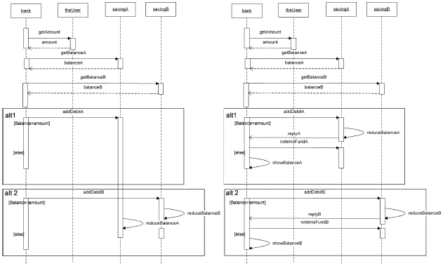
Figure 5 Problematic VS corrected sequence diagram.
The following are the CCS specifications of the sequence diagram of the Safe Withdraw pattern’s instance obtain by Theorem 4 and Definition 1 (they are automatically produced by the algorithm programmed in the Appendix):
CCS_bank=′CHgetAmount.CHamount.amount.′CHgetBalanceA.CHbalanceA.
balanceA.′CHgetBalanceB.CHbalanceB.balanceB.(condATRUE.
′CHaddDebitA+condAFALSE.′CHchargeFeeA.returnCheckA).(condATRUE.
′CHaddDebitA+condAFALSE.′CHchargeFeeA.returnCheckA).nil,
CCS_theuser=CHgetAmount.getAmount.′CHamount.nil,
CCS_savingA=CHgetBalanceA.getBalanceA.′CHbalanceA.(CHaddDebitA.
addDebitA.
reduceBalanceA+CHchargeFeeA.chargeFeeA).nil,
CCS_savingB=CHgetBalanceB.getBalanceB.′CHbalanceB.(CHaddDebitB.
addDebitB.
reduceBalanceB+CHchargeFeeB. chargeFeeB).nil,
CCS_SD=(CCS_bank|CCS_savingA|CCS_savingB|CCS_theuser)\
{CHgetAmount,
CHamount,CHgetBalanceA,CHBalanceA,CHaddDebitA,CHchargeFeeA,
CHgetBalanceB,CHBalanceB,CHaddDebitB,CHchargeFeeB}
(bold fonts represent alternative flows).
In each of the above CCS expressions, the left part of the equation is a CCS process name; the right part is its definition. Each label on the right part is a message. A message prefixed with′ is an outgoing message. Messages are joined by CCS operators ‘.’ or ‘+’. Messages joined by sequential operator ‘.’ (e.g. x.y) defines consequentially actions (message x is followed immediately by message y). Messages joined by choice operator ‘+’ (e.g. x+y) defines non-deterministic choices (either message x or message y). Each label (without ‘CH’) on the right part is a CCS message representing a message in a sequence diagram. Each label with ‘CH’ is a CCS message representing a channel used to pass that message. CH prefixed with ′ represents sending out the message. For example, ′CHbalanceB is a channel that sends out message balanceB.
In the instance, the safety property design_goal is instantiated into two properties:
prop designgoalA = AG ({addDebitA}→X{reduceBalanceA }) ∧ AG
({condTRUEA}→F{reduceBalanceA}),
prop designgoalB = AG ({addDebitB}→X{reduceBalanceB }) ∧ AG
({condTRUEB }→F{reduceBalanceB }).
The verification shows that design goal B is satisfied. Design goal A is, however, not satisfied. In other words, if saving account A’s constraint condition is satisfied and the user processes to withdraw cash, the balance of savings account A is not immediately reduced after the cash is withdrawn by the user. If the transaction system is programmed according to the instance, the user is able to perform a malicious action before message reduceBalance, e.g., the user could simply terminate the bank transaction and leave the withdraw amount not reduced from the savings account. This can bring great financial loss to the bank.
After studying the unsatisfied property and the sequence diagram for the bank savings account, we identify the problem: the message addDebitA is not synchronized. In a Safety Withdraw Pattern instance, although the invocation of reduceBalanceA is immediately after addDebitA in a generic pattern, the invocation of reducebalanceA may be delayed by the behaviors of object saving, which is shown in Figure 5 on the left. An attacker could exploit this to withdraw money exceeding his saving amount. To do this, the attacker initiates two withdraw actions (savingA and savingB) at almost the same time. Immediate after he got his cash from savingA, e.g., addDebitA is called, he asks for another withdrawal action. Since reducebalanceA has not been called, his withdraw action (of savingB) will be granted because the guard condition [Balance > Amount] is satisfied for savingB.
A correction is made by adding synchronizing message replyA immediately after the invocation of reduceBalanceA and adding replyB immediately after reduceBalanceB respectively. The correction is shown in Figure 5 on the right.
After the correction, the verification results show that both Design GoalA and Design GoalB are satisfied. This case study has demonstrated how model checking is performed to detect problems in security pattern instantiation, which can be difficult to discover by observation.
5 Security Patterns Integration Verification
5.1 Web Security Patterns
Security patterns have been adopted in the software industry to reuse expert design experience on solving security problems. Each security pattern presents a good solution to a security problem. In particular, web security patterns present solutions to reoccurred security problems in authentication, authorization and assuring confidentiality among network interactions. One particular type of authorization is introduced in the following context. The client needs to access one or more Web services that are distributed across a network. The Web services are designed so that access to additional resources (such as a database or other Web services) is encapsulated in the business logic of the Web service. The problem is that these resources must be protected against the unauthorized access. In other words, we must ensure that the client accessing the Web services cannot access the additional Web resources directly. Trusted Subsystem pattern is the solution to this problem.
As illustrated in Figure 6 on the left, the process of Trusted Subsystem is described in the following steps: (1) The client submits a request with client credentials to the trusted subsystem. (2) The trusted subsystem authenticates the user. Authentication can be direct or brokered. (3) The trust subsystem sends an access message accompanied with its credentials to the remote resources. (4) The resource authenticates and authorizes the trusted subsystem. It then processes the request and issues a response to the trusted subsystem. (5) The trusted subsystem processes the response and issues its own response to the client.
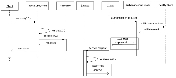
Figure 6 Trusted subsystem pattern and brokered authentication pattern.
The resource party must be able to verify that the mediate caller is a trusted subsystem and not just any system process. Requiring this type of verification enhances the security by making it more difficult for attackers to simulate a trusted subsystem and perform a man-in-the-middle attack. Several approaches can be used to implement trusted subsystem verification, such as the direct and brokered authentication [34]. In the direct authentication, the client directly proves its identity to the server. In the brokered authentication, both client and server trust a third party that handles the authentication. There are several protocols for brokered authentication, such as X.509 PKI and Kerberos [34]. Brokered Authentication pattern provides a flexible solution for exchanging one type of security token for another to accomplish a variety of goals in a Web service environment, such as authentication, authorization, and exchanging session keys. The solution is not dependent on any one mechanism, such as the Kerberos protocol or X.509 to secure messages. This makes it easier to enable different authentication protocols to be interchangeable.
The following steps describe the process of Brokered Authentication depicted in Figure 6 on the right. (1) The client submits an authentication request to the authentication broker. (2) The authentication broker contacts the identity store to validate the client’s credentials. (3) The authentication broker responds to the client, if the authentication is successful, it issues a security token. The client can use the token to authenticate requests to the service throughout the lifetime of the token. (4) Request message with the token is sent to the service. (5) The service authenticates the request by validating the token. (6) The service returns the response to the client.
5.2 Integration of Security Patterns
A security pattern may be integrated with other patterns to solve multiple security problems in a software application. The integration of two security patterns describes the particular ways that the two groups of classes are combined, which may include stringing (connecting them by some relationships) or overlapping (overlapping them at some classes).
Definition 6 (Design Pattern Integration). Let X1 < C1, R1, M1, N1 > and X2 < C2, R2, M2, N2 > be two design patterns. Their integration XT < C, R, M, N > is obtained by a many-to-one integration mapping T from (N1 ∪ N2) to N with the following properties:
(1) CT = T(C1) ∪ T(C2) is the set of classes in the integration. In overlapping integration, T(C1) ∩ T(C2) is a non-empty set. A class can carry its pattern name if needed, e.g., each class in C1 is written as X1_classname.
(2) RT = T(R1) ∪ T(R2) is the set of class relations of the integration. That is, any class relation in X1 and X2 is preserved in X. For example, let (A,B,r) ∈ R1, then (T(A),T(B), r) ∈ RT. Similarly, let (C, D, r2) ∈ R2, then (T(C),T(D),r2) ∈ RT. This property is especially meaningful for overlapped classes. Suppose B and C are overlapped classes, let Bc=T(B)=T(C). We have (T(A),Bc,r) ∈ RT and (Bc,T(D), r2) ∈ RT. This means class Bc is related to T(A) and T(D), and thus forms a composition.
(3) MT = T(M1) ∪ T(M2) is the set of methods invocations of the integration. That is, the caller class and called class of any method invocation in X1 and X2 are preserved in XT. For example, let (m, s1, e1) ∈ R1, then (T(m),T(s1), T(e1)) ∈ RT.
An application requires the integration of security patterns is presented [33]: Global Bank provides a customer account management application that allows client to access a centralized account management database through a Web service. The client must authenticate with the Web service to use the account management database. In this scenario, the Web service acts as a trusted subsystem by using its own credentials to access the account management database. The client application cannot log in to the account management database because this violates the security policy and bypasses the business logic. Web service needs to authenticate client and the database needs to authenticate Web service. The authentication protocols used by Web service and database can be different and changeable. Hence the application requires the integration of Trusted Subsystem pattern and Brokered Authentication pattern, which is illustrated in Figure 7.
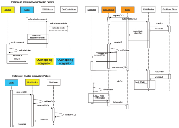
Figure 7 Patterns and their integration.
To overlap the classes in Brokered Authentication pattern and Trusted Subsystem, let the integration mapping be T = {(X1_Service, WebService), (X2_WebService, WebService), (X1_Client, Client), (X2_Client, Client)} and we obtain the following integration: XT < C, R, M, N >, where CT = {X509Broker, Client, CertificateStore, WebService, Database}, RT = {(Database, X509Broker, association), (Database, WebService, association), WebService, Client, association), (WebService, X509Broker, association)}, MT = {(requestCC, Client, WebServce), (authenticateCC, WebService, X509Broker),... }.
5.3 Security Analysis by Model Checking Alternative flows
Security patterns integration involves pattern instantiation and class overlapping. Integration’s behaviors become complicated because alternative flows and more classes are introduced. Hence it is important to ensure that the access control has been correctly implemented by the integration. The access control properties can be presented as: if the client fails to provide correct certification or the Web service fails to provide correct certification, the database must not pass information to the client. To apply model checking techniques to verify the access control property, we need the system model which describes the state transitions of the integration. We can obtain CCS specifications for integration by Theorem 4. However, the Theorem 4 CCS specifications represent all the transitions of the alternative flow system. If a system has n alternative flows, the Theorem 4 CCS model would have 2n state transition branches, each of which corresponds to an alternative flow. 2n state transitions can be exhausted by model checker, which is called state exposition problem. In order to avoid state explosion, we propose the following theorem that provides concise CCS specifications for alternative flows by introducing an extra expression (not appear explicitly in the sequence diagram) to set the value of the constraint condition.
Theorem 7 Suppose pattern Xalt contains alternative flows: if [condition] of Obj1 is true, then message a is sent; otherwise message b is sent. action1 and action2 present actions before and after the alternative flow segment. The CCS specification of Xalt is
CCS(Xalt)=condvalue|CCS(Obj1)| CCS(Obj2)\L1∪L2, where
CCS(Obj1)=action1.(TRUE.′CHa+FALSE.′CHb).action2 (CCS of Obj1),
CCS(Obj2)=CHa.a.CHb.b (CCS of Obj2),
condvalue ∈ {′TURE,′FALSE} (process for setting value of the constraint
condition),
L1={TRUE, FALSE} (set of condition value passing channels),
L2={CHa, CHb} (set of internal communicating channels).
It is provable that
CCS(Xalt) action1.(a.action2+action2.a) when condvalue=TRUE,
CCS(Xalt) action1.(b.action2+action2.b) when condvalue=FALSE,
which semantically indicate the alternative flows property: if constraint is satisfied, a is activated asynchronously with action2, if constraint is not satisfied, b is activated asynchronously with action2.
By using condition value expression condvalue to set constraint condition values, we reduce the number of choice-making branches of CCS(Xalt). In other words, while CCS(Xalt) in Theorem 4 models all possible state transition branches in the sequence diagram, CCS(Xalt) in Theorem 7 models only state transition branches corresponding to the constraint condition values set by condvalue. Condition value expression condvalue allows us to specify a system in some certain conditions that we are interested in.
Lemma 8 Suppose sequence diagram X has n alternative flows with constraint conditions cond1,cond2,..., condn, CCS expression of the condition is
condvalue = condvalue1 |...| condvaluen, where condvaluei ∈ {′condiTURE,
′condiFALSE}.
The condition value channels , where Si={condiTURE, condi FALSE}.
By applying Lemma 8, the CCS specification for object Database is obtained:
PROC DATABASE=CHaccessTSC.accessTSC.′CHauthTSC.CHdbCert.
dbCert.dbValidate.CHdbvTRUE.′CHinfo.nil.
The specifications for object WebService, Client, X509 Broker, Certificate Store are:
PROC WSERVICE=CHrequestCC.requestCC.′CHauthCC.CHserviceR.
serviceR.wsValidate.CHwsvTRUE.CHinfo.info.′CHinfo.nil.
PROC CLIENT=′CHrequestCC.CHclientCert.clientCert.′CHserviceR.
CHinfo.info.nil.
PROC XBKR=CHauthCC.authCC.CHccredits.CHccResult.ccResult.
CHccTRUE.
′CHclientCert.CHauthTSC.authTSC. ′CHwscredits.CHwsResult.
wsResult.CHwsTRUE/CHwsCert.nil.
PROC CSTORE=CHccredits.ccredits.′CHccResult.CHwscredits.wscredits.
′CHwsresult.nil.
The underlined channel names refer to the channels used to accept the constraint values of the alternative flows. Depends on the system model that we need to verify, we may select constraint condition values. In this case, we are interested in how the system behaves:
If both the Client and Web Server succeed in obtaining the certificates from X509 broker, the CCS specification for process condition value is
PROC CONDVALUE1=′CHwsvTRUE|′CHccTRUE|′CHwsTRUE|
′CHdbvTRUE.
If the Client fails to get the certificate from the X509 Broker, the CCS specification for process condition value is
PROC CONDVALUE2=′CHwsvTRUE|′CHccFALSE|′CHwsTRUE|
′CHdbvTRUE.
If the Web Server fails to get the certificate from the X509 Broker, the CCS specification for process condition value is
PROC CONDVALUE3=′CHwsvFALSE|′CHccTRUE|′CHwsTRUE|
′CHdbvTRUE.
Let L1 be the set of messages channels and L2 be the set of constrain values, the CCS specification for the Integration is as
PROC SYS1= (DATABASE|WSERVICE|CLIENT|XBKR|CSTORE|
CONDVALUE1)\L1∪L2,
PROC SYS2= (DATABASE|WSERVICE|CLIENT|XBKR|CSTORE|
CONDVALUE2)\L1∪L2,
PROC SYS3= (DATABASE|WSERVICE|CLIENT|XBKR|CSTORE|
CONDVALUE3)\L1∪L2.
where
L1={CHaccessTSC, CHauthTSC, CHdbCert, CHinfo, CHrequestCC, CHau-thCC, CHserviceR, CHclientCert, CHauthCC, CHccredits, CHccResult, CHwscredits, CHwsResult, CHwsCert, CHccResult, CHwscredits},
L2={CHwsvTRUE, CHwsvFALSE, CHccTRUE, CHccFALSE, CHwsTRUE, CHwsFALSE, CHdbvTRUE, CHdbvFALSE}.
The security property that we need to check against system model SYS1 is declared as SYS1|- EF {information}, which means that there exists a path of the SYS1 transitions where information will be sent finally to the Client. The security property that we need to check against system model SYS2 is declared as SYS2 |-not EF {information}, which means that there does not exist any path of the SYS2 transitions where information will be sent finally to the Client. The security property we need to check against system model SYS3 is declared as SYS3 |-not EF {information}, which means that there does not exist any path of the SYS3 transitions where information will be sent finally to the Client.
We used CWB-NC model checker to verify the three security declarations of SYS1, SYS2, and SYS3 respectively, which shows that those security properties of the integration are satisfied and ensure the correctness of the integration. (The screen shots of all model checking results are not presented to save pages).
6 Conclusions and Future Work
Security patterns have been adopted in the software industry to reuse expert design experience in solving security problems. While each security pattern presents a good solution to a security problem, it is essential to analyze the instantiation and integration of related patterns that normally involve complicated behaviors (alternative flows) and even inconsistencies. Failure of detecting such errors and problems may result in security loopholes that suffer from malicious attacks. Analysis at a higher level (architecture and design level) may greatly save time and efforts than that at the lower implementation level.
This paper presents an approach to verify the instantiation and integration of security patterns using model checking techniques. We propose formal definitions for security patterns’ instantiation and integration. We establish the rules to transform the behaviors of security patterns (presented by UML sequence diagrams) to Milner’s CCS expressions and propose an algorithm to automatically do the transformation. We prove that the synchronous message, asynchronous message, and alternative flows of a UML sequence diagram are transformed to CCS expressions truthfully. We provide two different methods to formally specify sequence diagrams with multiple alternative flows. One method specifies all branches that can be reached by the sequence diagrams; another method specifies some specific branches guarded by the constraint conditions that we are interested in. The designer can choose between the two ways to gain a complete system model with many state transitions or a trimmed model with fewer state transitions for model checking. We present two case studies to illustrate our approach. By model checking security patterns instantiation, we were able to detect subtle errors. By model checking security patterns integration, we proved the correctness of a complicated design.
Our approach consists of model checking and CCS specifications whose truthfulness is proved by mathematically. Hence the verification result is rigorous and trustworthy. This makes our approach suitable for checking security problems in software design and provides security assurance. Since model checking process is largely automatic reduces potential errors caused by manual verification. Moreover, the transformation can be done automatically by the algorithm, which takes in a sequence diagram and then transforms synchronous messages, asynchronous messages, and alternative flows of it into CCS expressions. CCS expressions are passed to the model checker for behavior analysis. Currently, there has been no work on programmable algorithms for formal specification of security pattern integration in CCS.
A common limitation of model checking technique is called state explosion [34]. Our approach may be less effective if the software design is very complex: the sequence diagrams contain more states than a model checker can exhaust (usually called state explosion). In fact, state explosion happens when sequence diagrams consisting of many choice-making branches (alternative flows) are transformed to CCS specifications. In this case, we could apply divide-and-conquer strategy to reduce the complexity of the system by splitting it into several sub-systems, which are set by the constraint conditions’ values. Each sub-system consists of only a few alternative flows, on which model checking can be applied. It is critical that the security property of the entire system needs to be decomposed carefully into security properties of these sub-systems. Another way to deal with system complexity is to select and verify a part of security patterns, which are most closely related to expected security properties, instead of all patterns of the system.
Our approach is not tied to a particular model checker. Instead, it is applicable to other CCS-based model checkers, such as XMC or Edinburgh CWB. Future studies include visualizing the verification by displaying message invocation sequences together with temporal properties. Automatically transforming security patterns integration to CCS expressions and verifying the equivalence of two integrations are also in our future plan.
Acknowledgements
Thank Professor EDMUND M. CLARKE for his valuable advice and help. This work is supported by the National Science Foundation of China (Grant No. 61472039; 61502034).
References
[1] Abrial, J. R. 1996. The B-book. Cambridge University Press Cambridge. DOI: http://dx.doi.org/10.1017/CBO9780511624162
[2] Cleaveland, R., Parrow, J. and Steffen, B. The Concurrency Workbench: A semantics-based tool for the verification of concurrent systems. ACM Trans. on Prog. Lang. and Systems. 15,1 (1993), 36–72. DOI: http://dx.doi.org/10.1145/151646.151648
[3] Browne, M., Clarke, E. and Dill, D. Automatic Verification of Sequential Circuits Using Temporal Logic. IEEE Transactions on Computer. C-35,12 (1986), 1035–1044.
[4] Dong, J., Peng, T. and Qiu, Z. Commutability of Design Pattern Instantiation and Integration. In the Proceedings of the First IEEE & IFIP International Symposium on Theoretical Aspects of Software Engineering (TASE). China, June 2007, pp. 283–292. DOI: http://dx.doi.org/10.1109/TASE.2007.14
[5] Dong, J., Peng, T. and Zhao, Y. Automated Verification of Security Pattern Compositions. In Information and Software Technology (IST), Elsevier-Science. 53,3 (2010), 274–295. DOI: http://dx.doi.org/10.1016/j.infsof.2009.10.001
[6] Dong, J., Peng, T. and Zhao, Y. On Instantiation and Integration Commutability of Design Pattern. The Computer Journal, Oxford University Press. 54, 1 (Jan. 2011), 164–184. DOI: http://dx.doi.org/10.1093/comjnl/bxp125
[7] Peng, T., Dong, J. and Zhao, Y. Verifying Behavioral Correctness of Design Pattern Implementation. In the Proceedings of the 20th International Conference on Software Engineering and Knowledge Engineering (SEKE). CA, USA, July 2008, pp. 454–459.
[8] Peng, T. and Ding, G. Formal Specification and Automated Verification of UML2.0 Sequence Diagrams. In 2012 IEEE International Conference on Granular Computing. Hangzhou, China, 370–375. DOI: http://dx.doi.org/10.1109/GrC.2012.6468641
[9] Dwyer, M., Avrunin, G. and Corbett, J. Patterns in property specifications for finite-state verification. In Proceedings of the 21st International Conference on Software Engineering. Los Angeles, USA, May 1999, pp. 411–420.
[10] Emersion, E. and Halpern, J. ‘Sometime’ and ‘not never’ revisited: on branching versus linear time temporal logic. Journal of the Association for Computing Machinery. 33,1 (1986), 151–178.
[11] Eshuis, Rik, and Roel Wieringa. 2004. Tool support for verifying UML activity diagrams. Software Engineering. IEEE Transactions. 30,7 (2004), 437–447. DOI: http://dx.doi.org/10.1109/TSE.2004.33
[12] Gamma, E., Helm, R., Johnson, R. and Vlissides, J. Design Patterns: Elements of Reusable Object-Oriented Software. Addison-Wesley.
[13] Holzmann, G. The Model Checker SPIN. IEEE Transactions on Software Engineering. 23,5 (1997), 279–295. DOI: http://dx.doi.org/10.1109/32.588521
[14] Li, J. and Chen, F. The Z specification-based method for the semantic analysis of UML sequence diagrams. Journal of Xidian University (Natural Science). 30,4 (2003), 519–524 (in Chinese with English abstract).
[15] Kong, J., Zhang, K., Dong, J. and Xua D. 2009. Specifying behavioral semantics of UML diagrams through graph transformations. Journal of Systems and Software. 82,2 (2009), 292–306. DOI: http://dx.doi.org/10.1016/j.jss.2008.06.030
[16] Johan, L., and Paltor, I. vUML: A tool for verifying UML models. In 14th IEEE International Conference on Automated Software Engineering. Cocoa Beach, Florida, 255. DOI: http://dx.doi.org/10.1109/ASE.1999.802301
[17] Li, X., Liu Z., and He, J. A Formal Semantics of UML Sequence Diagrams. In The Proceedings of ASWEC2004. Melbourne, Australia, pp. 13–16.
[18] Lima, V., Talhi, C., Mouheb, D., Debbabi, M. and Wang, L. Formal Verification and Validation of UML 2.0 Sequence Diagrams using Source and Destination of Messages. Electronic Notes in Theoretical Computer Science. 254 (2009), 143–160.
[19] Mikkonen, T. Formalizing Design Pattern. In Proceedings of the 20th International Conference on Software Engineering. Kyoto, Japan, April 1998, pp.115–124. DOI: http://dx.doi.org/10.1109/ICSE.1998.671108
[20] Pnueli, A. and Harel, E. Applications of Temporal Logic to the Specification of Real-time Systems. Springer. DOI: http://dx.doi.org/10.1007/3-540-50302-1_4
[21] Meyer, B. Applying “design by contract”. IEEE Computer. 25,10 (1992), 40–51.
[22] Milner, R. Communication and Concurrency. International Series in Computer Science. Prentice Hall.
[23] Saeki, M. Behavioral specification of GOF design patterns with LOTOS. In Proceedings of the Seventh Asia-Pacific Software Engineering Conference (APSEC). Singapore, 408–415.
[24] Storrle, H. Trace Semantics of Interactions in UML2.0. Technical report, LMU Munchen.
[25] Yoshioka, N., Honiden, S. and Finkelstein, A. Security patterns: a method for constructing secure and efficient inter-company coordination systems. In Proceedings of Enterprise Distributed Object computing Conference 2004 (EDOC’04). 87–97. DOI: http://ieeexplore.ieee.org/xpl/articleDetails.jsp?arnumber=1342507
[26] Yoshioka, N., Washizaki, H. and Maruyma, K. A survey on security patterns. Progress in Informatics. No. 5 (March 2008), 35–47. DOI: 10.2201/NiiPi.2008.5.5
[27] Steel, C., Nagappan, R. and Lai, R. Core Security Patterns: Best Practices and Strategies for J2EE, Web Services, and Identity Management. Prentice Hall PTR.
[28] Toufik Taibia and David Chek Ling Ngo 2003. Formal specification of design pattern combination using BPSL. International Journal of Information and Software Technology. Elsevier-Science, 45,3 (2003), 157–170.
[29] Viega, J. and McGraw, G. Building Secure Software: How to Avoid Security Problems the Right Way. Addison-Wesley.
[30] Zhang, C., Duan Z. and Tian C. Specification and verification of UML2.0 Sequence diagram based on Event Deterministic Finite Automat. Journal of Software. 22,11 (2011), 2625–2638.
[31] Zhou, X. and Shao., Z. ASM semantic modeling and checking for sequence diagrams. In Proc. of the 5th Int’l Conf. on Natural Computation. Washington: IEEE Computer Society, pp. 527–530.
[32] IBM developers Work. 2004. UML basics of Sequence Diagrams. IBM developers Work. http://www.ibm.com/developerworks/rational/library/3101.html
[33] Microsoft Corporation. 2006. Web Service Security Pattern and Practice. March 2006. 175–177.
[34] Microsoft.com. 2005. Web Service Security. http://msdn.microsoft.com/en-us/library/aa480545.aspx; Microsoft.com. 2005. Brokered Authentication. http://msdn.microsoft.com/en-us/library/aa480560.aspx
[35] Clarke, E. and Wang Q. 2^5 Years of Model Checking. Ershov Memorial Conference 2014: 26–40.
Biographies

Tu Peng received his B.Sc. and M.Sc. degrees in Mathematics from Peking University, China; and Ph.D. degree in Software Engineer from University of Texas at Dallas, USA. He is currently an associate professor in school of computer science, Beijing Institute of Technology. His research interests include software testing, verification, architecture and machine learning.

Shuliang Wang received his Ph.D. degree in Computer Science from Wuhan University, China. He is currently a professor in Beijing Institute of Technology, China. His research interests include spatial data mining, and software engineering. For his innovatory study of spatial data mining, he was awarded the Fifth Annual InfoSciÒ-Journals Excellence in Research Awards of IGI Global, and one of the best national thesis in China.

Jing Geng received her B.Eng. degree in Software Engineer from University of Electronic Science and Technology of China; and Ph.D. degree in Photogrammetry and Remote Sensing from WuHan University, China. She is currently an assistant research fellow in Beijing Institute of Technology. Her research interests include spatial data mining, Geospatial knowledge service.

Qinsi Wang is an independent postdoctoral researcher in the group of Prof. Jean Yang at Carnegie Mellon University. She received her PhD in Computer Science at CMU under the supervision of Prof. Edmund M. Clarke (Turing Award 2007) in Sep 2016. Her research interest is to develop formal specification and verification techniques for real-world systems with the emphasis on statistical model checking for models of biological signaling networks, stochastic SMT-based methods for stochastic hybrid systems, and combining model checking techniques with machine learning methods for the study of biological systems and causal networks.

Yun Yang is part of the Swinburne University School of Software and Electrical Engineering. His research expertise spans areas including cloud computing, workflows, distributed systems, software development environments and service-oriented computing. Alongside his teaching and research responsibilities, Professor Yang is also the leader of Swinburne’s Next Generation Software Platform focus area and Associate Editor of IEEE Transactions on Cloud Computing.

Kang Zhang received his B.Eng. degree in Computer Engineering from University of Electronic Science and Technology of China; and Ph.D. degree in Computer Science from the University of Brighton, UK. He is currently a professor in department of computer science, the University of Texas at Dallas, USA.
Journal of Web Engineering, Vol. 19_3-4, 521–556.
doi: 10.13052/jwe1540-9589.19347
© 2020 River Publishers