A Method of Stereoscopic Display for Dynamic 3D Graphics on Android Platform
Shihong Chen1,* and Zi Jiu2
1Applied Arts and Science College, Beijing Union University, Beijing, China
2School of Digital Art and Animation, Communication University of China, Beijing China
E-mail: csh398@126.com
*Corresponding Author
Received 26 August 2020; Accepted 21 October 2020; Publication 12 December 2020
Abstract
With the widespread use of smart terminals, the convenient use of stereoscopic video display on mobile platforms is urgently needed by more and more people. This study presents a method to rapidly convert 3D dynamic graphics produced by 3D animation software into stereoscopic display suitable for the Android platform, with details of an algorithm to generate double-viewpoint image sequences from single-viewpoint 3D dynamic graphics, and a method for compositing stereoscopic display from double-viewpoint image sequences. It developes a program on the basis of popular animation software to implement this method for realizing automatic generation of dynamic 3D graphics and for outputting composite images that conforms to the binocular characteristics of stereoscopic displays. As shown by experiments, the methods presented by this study, produce better results at a faster speed and provide stronger support for the production of high-quality stereo videos.
Keywords: Stereoscopic display, dynamic 3D graphic, parallax.
1 Introduction
Vision is an important way for human to perceive the objective world, images and video are effective means for people to obtain information [1]. The development of image and video technology is more perfect in the terms of “digitalization” and “high-definition”, but there is still a lot of space for development in terms of “stereoscopicizing” [2]. The display technologies of traditional two-dimensional image and video ignore the far and near position of the object and the depth information of the third dimension of the real physical world, and they have difficulties with accurately representing the three-dimensional spatial relationship of objects in the real physical world. Therefore people are no longer satisfied with these 2D displays and are committed to researching stereoscopic technology that can display three-dimensional depth information of a scene. This problem of visual display in the field of virtual reality has been solved by stereoscopic display technology, which can, give viewers an immersive sense of being in a scene reproduced as images that expresses the hierarchical sense, depth and authenticity of the objective world, to a certain extent.
As stereoscopic technology develops, the production of stereoscopic video source is becoming increasingly important for achieving the display of high-quality three-dimensional effects. Using computer to generate truly stereoscopic display has the characteristics of convenience, flexibility and ease of operation; it has gradually become an important way to generate stereoscopic display. Researchers in this area have done a lot of work [3–8], and they have achieved some results [9, 10]. However, with the ubiquitous use of mobile smart terminals, it is practical significance to study stereoscopic technology based on the characteristics of mobile smart terminals for providing real-time stereoscopic display on them.
In this paper, the method of fast conversion of dynamic three-dimensional graphics produced by three-dimensional animation software to generate stereoscopic display, and the method suitable for Android platform display is studied. This paper introduces the algorithm of generating double view image sequence from single view dynamic 3D graphics in detail, and the method of synthesizing double view image sequence into stereoscopic display. On the basis of popular animation software, the corresponding program is developed to realize the automatic generation and synthesis of 3D dynamic graphics stereoscopic display based on mobile platform. Using this method, the 3D dynamic graphics can be converted into 3D stereoscopic display, which is expected to provide a feasible scheme for the production of high-quality stereoscopic display video.
2 The Method of Generating and Compositing Stereoscopic Display
2.1 Principle of Stereo Vision
Human left and right eyes are slightly apart horizontally, for about 6 to 7 centimetres in distance; therefore, when viewing objects, both eyes see slightly different images actually. When these two parallactic images are transmitted to the brain, the brain perceives them as a scene with depth, and can sense the changing positions in the third dimension (perpendicular to the image plane) of objects in the scene as changes in depth [11]. That’s how stereo vision works.
The way of image separation for achieving stereoscopic effect seen through chromatic 3D glasses, also known red and blue glasses, is done by color filtering. The images acquired from different viewpoints are filtered differently but placed on the same picture. To a user wearing red and blue glasses, this combined picture is again filtered so that the left and right eyes can only see the left image and the right image respectively, because the picture in red passes the red lens while the picture in blue passes the blue lens. The two eyes thus see different pictures, which are fused by the brain to produce stereoscopic vision.
2.2 Algorithm for Generating Stereoscopic Images
For generating stereoscopic videos, two cameras are set up in computer software according to the principle of stereo vision, in a way similar to the positioning of human eyes [12].
Suppose the coordinates of a point C in the space is (). Then, the coordinates of the left viewpoint SL can be written as (), that of the right viewpoint SR as (), and that of the visual center as (). See Figure 1. As such, the equation of the visual plane A is as follows:
| (1) |
The angle between the left and right views and the horizontal line is , which is the camera’s roll angle. See Figure 1.
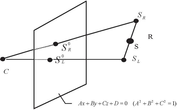
Figure 1 Parallax projection of points.
The coordinates of S and S according to the rotation and translation formulas are as follows:
| (2) | |
| (3) |
It can be seen that for any point in space, according to the above formula, the coordinate positions of the left and right viewpoints can be obtained. In other words, we can calculate the coordinates of left and right view points by formula derivation method when we know the coordinates of view center point and the rolling angle of camera, and then get the transformation sequence pair of images, that is, to generate the left and right image pair sequence of stereoscopic display. This is how stereoscopic display is generated.
2.3 Complementary Color Stereoscopic Compositing Method
The human brain can fuse images of the left and right viewpoints into an image with depth. To facilitate this, the computer needs to do image compositing that fuses the information of two image together. After receiving a pair of images simulating binocular vision, it keeps only the red and the other channels respectively in the image pair with binocular parallax, and use the method of alpha transparency compositing to combine images for stereoscopic display so that people wearing chromatic 3D glasses can see stereoscopic effects.
Images consist of pixels, and the color of each pixel is composed of RGB values, where R stands for red, G for green and B for blue, which are often referred to as the three primary colors [13]. RGB value ranges from 0 to 255, and the lower the value, the lower the brightness. The pixel values of each point in the composite image consist of the pixel values of the corresponding points in the image pair used to make the composite image, which are mixed according to the Alpha values. The specific formula for calculating this is as follows [14]:
| NewPixelValR | (4) | |
| NewPixelValG | (5) | |
| NewPixelValB | (6) |
In the formulas, Pixel1ValR/G/B represent the grayscale values of the current pixel point of image 1, while Pixel2ValR/G/B represent the grayscale values of the current pixel point of image 2; The value of Alpha ranges from 0 to 255, indicating the weighting of these two in the final composite result [15]. By modifying the value of alpha, the ratio of the two images used for synthesis in the synthesized image can change, thus changing the display effect after the compositing.
3 Experimental Detail of Stereoscopic Display on Android Platform
3.1 Overall Structure of the System
The overall block diagram of the system is as follows:
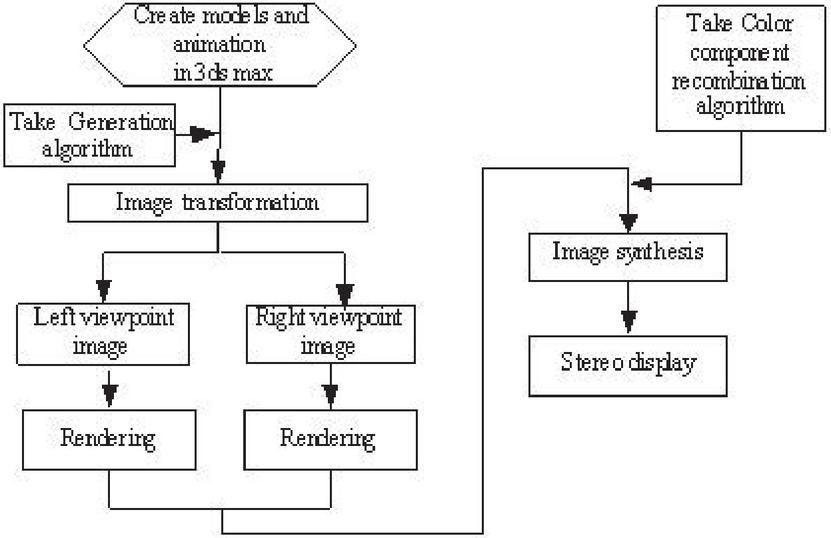
Figure 2 Schematics of the system structure.
The overall block diagram of the stereoscopic display system based on three-dimensional graphics in motion is shown on Figure 2. First animation software is used to make simulation animation.
3ds Max platform is chosen to set models, scenes, lights, materials, actions and cameras. The main function of the stereoscopic display system for animation is to generate two cameras according to the single-view camera set up earlier in the animation. The system renders the animation of the two camera viewpoints separately to simulate two human eyes, and it sets the renderer to render video suitable for mobile display. Finally, according to the results of rendering, it composites the two image sequences rendered into stereoscopic video.
3.2 Generating Stereoscopic Animation
In the production of three-dimensional animation using three-dimensional animation software, although a scene in animation has three dimensions of spatial data, what we see on screen are different perspectives of the scene on two-dimensional display. According to the formulas above in Section 2.2, we need to generate a double-viewpoint animation first from a single-viewpoint animation. That means we need to generate two cameras based on a single camera according to certain requirements. According to the formulas above in Section 2.2, further transformation can be done to determine the position of the left and right camera [16].
Suppose the current camera’s coordinate system is EUVW, see Figure 3. Where UV and W are unit vectors, then they can be determined by the camera’s target point, the position of the viewpoint, and the roll angle of the camera.

Figure 3 UVW coordinate system of camera.
If the horizontal distance of the left and right viewpoints is given as d, the camera coordinate system at the left and right viewpoints would be ELUVW and ERUVW, where:
| (7) |
With this result, views of the left and right cameras can be generated.
3ds Max provides two programming languages: VC++ and MAXScript. In the process of animation production, the computer calculates trajectories by interpolating key frames. Because the camera can also be animated, our system’s programming also needs to consider the camera’s key frames. To use the 3ds max scripting language to do this is a simple and practical way.
There are target cameras and free cameras in 3ds max. The target camera contains two objects: a viewpoint and a target point. For the target camera, in general, both the viewpoint and the target point must be specified. Table 1 shows several attribute parameters for camera control in the scripting language of 3ds max. In this way, ten attribute parameters and three positional parameters of X, Y and Z are required to fully control the target camera. After knowing how to control the camera, you can generate a pose animation based on the automatically generated method.
Table 1 Camera attribute parameters
| Public Attribute Parameters | Type of Data | Attribute Parameters | Type of Data |
| camera.orthoProjection | BooleanClass | TargetCamera.fov | Number |
| camera.showCone | BooleanClass | TargetCamera.nearrang | Number |
| camera.showHorizon | BooleanClass | TargetCamera.farrange | Number |
| camera.showRanges | BooleanClass | TargetCamera.nearclip | Number |
| camera.clipManually | BooleanClass | TargetCamera.farclip | Number |
The process of implementation of the plan is as follows:
1. Get the number of key frames of the camera in the animation. If the camera’s motion is set by parametric controllers, convert it into key frame animation first.
2. Read the key-framed parameters of the camera.
3. Determine the distance between the left and right viewpoints.
4. Determine the coordinates of the left viewpoint camera and of the right viewpoint camera according to formula (7) above.
5. Duplicate the camera and place the two cameras in the position corresponding to the left and right viewpoints.
6. Determine whether the current key frame is the last key frame and, if so, end the program; if not, go back (to step 2) and read the next key frame in order to repeat the steps above.
3.3 Rendering of Animation
The Render Function of 3ds max can be used to call its renderer to render a video suitable for mobile platform display [17–19]. Before rendering, it is necessary to find out whether there are paired left and right cameras in the scene. If there are paired cameras, render and obtain the rendered video. In the rendering process, attention should be paid to the setting of parameters, especially the setting of parameters Output width and Output height. Considering that the intended playback platform is a mobile device based on the Andriod platform, the parameters Output width and Output height are set to 1920 and 1080 respectively, to meet the needs of mobile phone viewing.
3.4 Compositing of Stereoscopic Video
Because the video is viewed by means of color filtering, the main purpose of compositing is to process the color of the rendered image sequence of left and right eyes separately [20, 21]. Chromatic 3D glasses are actually red and cyan glasses; its red filter for the left eye only let red light pass through, and its cyan filter for the right eye only let green light and blue light through. This results in two pictures displaying the parallax fused by the brain to present us with the experience of stereoscopy [32].
In order to achieve this effect, the videos rendered need to be processed for this separation by color filtering accordingly. Applying programmatically the formulas (4), (5) and (6) above to the image pair obtained, only red is kept for the left eye view while only green and blue is kept for the right eye view, as shown on Figure 4. This allows viewers to see the stereoscopic image with so-called red and blue glasses. Figure 5 shows a frame of left and right viewpoint of Siheyuan in Beijing.
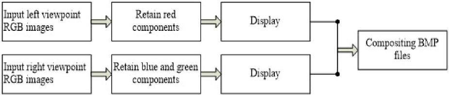
Figure 4 Color component recombination diagram.
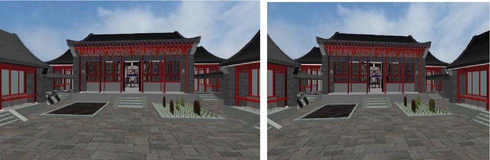
Figure 5 A frame of left and right viewpoint of Beijing Siheyuan.
4 Experimental Result and Analysis
By using the above method, the stereoscopic display of the Beijing Siheyuan Tour system has been completed. At present, the mainstream video players, such as Storm Video and QQ Video support the playback of red and blue videos [22, 23]. After the experimental test of the Beijing Siheyuan Tour system, the viewing effect has been shown to be good. Figure 6 shows a composited frame of the stereoscopic display of a quadrangle courtyard (i.e. a siheyuan) in Beijing.
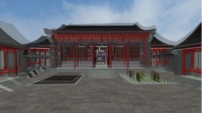
Figure 6 A composited frame of Siheyuan in Beijing.
The observation effect is shown in the table below, after 25 people’s actual obsrvation test. There are different results depending on the brightness and the complexity of the scene.
Table 2 The test results in bright environment
| Test Video | Observation Results | |
| Brightness | Dim | Very bad |
| Middle | Preferably | |
| Bright | Good | |
| Complexity of Scene | Low | Very bad |
| middle | Bad | |
| High | Preferably | |
Table 3 Test results in dark environment
| Test Video | Observation Results | |
| Brightness | Dim | Preferably |
| Middle | Gdod | |
| Bright | Good | |
| Complexity of Scene | Low | Very bad |
| Middle | Bad | |
| High | Preferably | |
The biggest advantage of chromatic stereoscopic display is low requirements for playback devices. Chromatic stereoscopic videos are viewable on pad and mobile phone with the use of low-cost red and blue glasses ranging from a few to a few dozen China Yuan . Without wearing red and blue glasses, such videos show double images; through red and blue glasses, one can get from these videos a stereoscopic experience immediately.
The following problems may arise when wearing red and blue glasses [24–28]:
1. Bad glasses. Red and blue glasses require the RGB value of the red lens to be as close to 255 as possible, and similarly for the right lens. If the glasses are not good enough, the light transmittance is poor, double image or ghosting may occur. It is found that red lenses are more likely to filter badly, while cyan lenses are adequate in many cases.
2. Screen with color bias that require adjustments. There is a close relationship between the effectiveness of chromatic stereoscopic images and color. color displayed too dark or too light will affect the stereoscopic effect. Tests show that turning screen to a warmer color temperature is better.
3. Brightness of the display and lighting conditions. There is a difference in the effectiveness of stereoscopic displays with different brightness. Also, viewing at night is more effective than during the day.
4. A mismatch between the red and blue of the image and those of the glasses. Different displays reproduce colors of films differently. One can adjust the brightness and saturation of the screen for the best effect.
5. Problematic source material. Many online sources filter 3D movies for chromatic 3D glasses but often there are people who recompress the videos afterwards, resulting in materials that are prone to ghosting.
6. After wearing chromatic 3D glasses, pepoples’ visual pigments need some time to recover, and see complementary colors during this process.It lasts longer in a dark environment.
5 Conclusions and Future
This paper introduces in detail a method of converting stereo display 3D graphics in motion, an algorithm for generating double viewpoint images from single viewpoint images, and the method of compositing binocular images into stereoscopic images. On the basis of popular animation software, a corresponding program is developed for the automatic generation and compositing of stereoscopic videos. The use of this method realizes the conversion of 3D animation for stereoscopic display, and can provide strong support for the production of high quality stereoscopic animated works, to be used widely in simulation, games and other fields with good practical value [29].
The use of red and blue glasses for achieving a stereoscopic viewing experience puts no extra demand on the display hardware. It is in line with the current general state of mobile phone screens. This system provide a low-cost solution for effective stereoscopic viewing, using the complementary color synthesis method, using red and blue glasses with low cost and good viewing effect. However, this method also has its limitations. In the process of image synthesis, it requires developers to modify manually in some details. And Red and blue glasses are not conducive to long-term viewing, eyes are easy to fatigue [30, 31] many scholars began to study naked eye display. At present, most of the naked eye 3D technology is in the research and development stage, the technology is not mature enough, the cost is high, and it has not been widely used in consumers. With the development of hardware and software technology, in the future, naked eye 3D technology may be fully applied [33]. But at present, there is still a lot of vitality in the application of dynamic 3D graphics in mobile platform, especially in teaching.
Acknowledgements
This paper is supported by 2019 national cultural and tourism science and technology innovation project of the Ministry of Culture and Tourism “Application demonstration of immersive roaming cockpit technology in cyberoom tourist attractions”.
References
[1] Huang Pengcheng, Jiang Jianyu, Yang Bo. Research Status and Progress of binocular stereo vision. Optical Instruments, 2018, 40(4): 81–86.
[2] Zeng X Y, Zhao Y, Guo T L, et al. Application and development of stereoscopic display in virtual/augmented reality technology. Video engineering, 2017, 41(9/10):135–140.
[3] Guo Huayuan, Qin Kahuai, Mao Miao, et al. Real-Time Tiled Multi-projector Autostereoscopic Display Algorithm for Dual-view 3D Video Files. Journal of Computer-Aided Design & Computer Graphics, 2015, 27(09):1734–1742.
[4] Saveljev V, Palchikova I. Analysis of autostereoscopic three-dimensional images using multiview wavelets. Applied Optics, 2016, 55(23): 6275.
[5] Jiao L, Shu X, Wu X. LED Backlight Adjustment for Backward-Compatible Stereoscopic Display. IEEE Signal Processing Letters, 2013, 20(12):1203–1206.
[6] Comlekciler I T, Gunes S, Rgin C. Three-dimensional repositioning of jaw in the orthognathic surgery using the Ortho gnathic surgery using the Binocular stereo Vision. International Journal of Science & Technology, 2017. doi:10.24200/SCI.2017.4351.
[7] Wang Danting, Jiang Youyu. 3D-virtual modeling for historic architecture and realization of virtual interactive software. Journal of Computer Applications, 2017, 37(S2):186–189.
[8] Wang Shulu, Ming Hai, Wang Anting, et al. There-Dimensional Based on Human Visual Perception. Chinese Journal of Lasers, 2014, 41(2):73–80.
[9] Wu X L, Du T Y, You Z X, et al. System of high fidelity 3D capturing and real-time display. Video engineering, 2017, 41(3): 15–21.
[10] Luo Y T, Zhu X U, Huang W, et al. Virtual fire extinguishing system based on 3D stereo technology. Journal of the HeFei University of Technology, 2015, 38(7): 934–937, 1003.
[11] Zhu Ziqi, Ding Yan. Calibration and Positing Algorithm based on Viewing Angle of the Camera. Optical Technique, 2015, 41(02):181–184+192.
[12] Huang Xinyuan, Tang Liangrui. The generating method of parallax animation. Journal of Computer Aided Design and Computer Graphics, 1999, 11(5): 409–411.
[13] Yang Min. Design of complementary color stereodisplay animation based on CATIA. Intelligent Computer and Applications, 2016, 6(1): 104,107.
[14] Zhao Zuolin, Huang Xinyuan. Image Volume Visualization System Based on Mobile Devices. Video Engineering, 2012, 36(06): 80–83.
[15] Tang Ruibin, Zhu Wenqing, Chen Fen, Zhang Ting, Sun Xiaoqi. Design of stereoscopic video displayer based on red and blue glasses. Microcomputer and application, 2015, 34(21):34–36.
[16] Huang Xinyuan, Ge Jiantao, Chen Shihong. The Generating and Composing System of Stereopsis Animation, 2001, 18(1): 19–21, 6.
[17] Li Yongcheng, Li Mengyu. A method of making three-dimensional images using 3D model. Computer Era, 2018(09): 62–65, 68
[18] Kong Suran, Yin Junping. Design of image texture real-time rendering system for three-dimensional animation. Modern Electronics Technique, 2018, 41(05):102–105.
[19] Duan Huili, Tang Liyu. Using OSG graphic rendering engine to achieve skeletal animation. Computer Engineering and Applications, 2015, 51(03):40–44.
[20] Zhou Yuxuan, Liu Dan, Yue Jun. An Efficient Adaptive Rendering Algorithm for SVG Animation. Microelectronics & Computer, 2017, 34(08):93–98.
[21] Xia Zhenping, Cheng Cheng. Stereoscopic Display Image Depth Adjustment Based on Visual Saliency. Acta Optica Sinica, 2017, 34(08):93–98.
[22] Jiang Ruikai, Ha Qinghua. Design of real time stereoscopic display system based on binocular web cameras uncalibrated. Chinese Journal of Liquid Crystals and Displays, 2014, 29(06): 1144–1150.
[23] Ma Jianshe, Zhao Xuejiang, Su Ping. Key Technology Research on Playing Stereoscopic Video in Android System. Video Engineering, 2013, 37(06): 89–91.
[24] Wang Tonghao, Liu Bingqi, Huang Fuyu, et al. Comfortable Area of Stereoscopic. Optical Technique, 2018, 44(2): 237–240.
[25] Zou Bochao, Liu Yue, Guo Mei. Stereoscopic Visual Comfort and Its Measurement: a Review. Journal of Computer-Aided Design & Computer Graphics, 2018, 44(2): 237–240.
[26] Xia Zhenping, Li Xiaohua, Chen Lei, et al. Study on Evaluation of Motion Blur in Binocular Parallax Based Stereoscopic Displays. ACTA OPTICA SINICA, 2018, 30(09): 1589–1597.
[27] Xia Zhenping, Li Xiaohua, Chen Lei, et al. Objective Evaluation of Flicker in Stereoscopic Display with Active Shutter Glasses. ACTA OPTICA SINICA, 2013, 33(12): 361–365.
[28] Zhang Li, Ren Jie, Xu Liang, et al. Visual comfort and fatigue measured by eye movement analysis when watching three-dimensional displays. Ophthalmology in China, 2014, 23(01): 37–42.
[29] Angelo G. Solimini. Are There Side Effects to Watching 3D Movies? A Prospective Crossover Observational Study on Visually Induced Motion Sickness. PLOS ONE, 2013, 8(2), p. e56160.
[30] Gao Qiang, Jin Jie, Shen Lili, et al. Effect analysis of horizontal parallax on 3D image comfortableness using EEG. Infrared and Laser Engineering, 2014, 43(12): 4140–4145.
[31] An Rui, Zhao Yan, Wang Shigang, et al. Visual Comfort Improvement of 3D Video Based on Parallax Change Continuity Adjustment. Journal of Jilin University (Information Science Edition), 2016, 34(01): 34–38.
[32] Li Pengfei, Shao Feng. Stereoscopic color transfer and disparity remapping based on selected object. Opto-Electronic Engineering, 2019, 46(09):13–21.
[33] Guo Yu. A New Way of Stereoscopic Display: Exploring 3D Display Technology of Naked Eye Based on Rotating Array LED. Art & Design. 2019, 318(10): 128–129.
Biographies

Shihong Chen, female, professor of Beijing Union University. She graduated from computer aided design center, School of vehicle engineering, Beijing Institute of Technology. Her current research interest is computer application, digital media technology and computer education.

Zi Jiu, Ph. D., School of Animation Art, Communication University of China. Her hometown is Inner Mongolia, Her main research areas are interactive animation, interactive picture book, Virtual Reality and so on.
Journal of Web Engineering, Vol. 19_5-6, 849–864.
doi: 10.13052/jwe1540-9589.195612
© 2020 River Publishers