Artificial Neural Network Controller for Automatic Ship Berthing Using Separate Route
Li Qiang* and Hong Bi-Guang
Navigation College, Dalian Maritime University, No.1, Lingshui Road, Dalian, China
E-mail: manumail@163.com
*Corresponding Author
Received 27 August 2020; Accepted 22 September 2020; Publication 22 December 2020
Abstract
The operation of ships in the port area requires not only the assistance of in-vessel equipment such as main engines and rudder, but also the assistance of external equipment such as tugboats. The complexity in the operation of ships in the port, requires control algorithm with multiple input and output for the automatic berthing control of the ship. The entering and leaving data of the ship can help the algorithm to efficiently control the berthing and un-berthing process of ships. This is based on the artificial intelligence which has been continuously approaching the operating habits of the pilot. The advances in artificial intelligence can control the entering, turning, and berthing in the port by artificial intelligence. In this study, the artificial neural network algorithm has been used to establish an automatic berthing model, based on the scheduled route. With the help of training data of one port, this model can be applied to the ship’s berthing with different berth layouts. Furthermore, it can also be applied to complex systems such as direct or turning-berthing of a ship. Finally, the automatic berthing model has been used for the simulation of direct berthing and turning-berthing in different berth.
Keywords: Ships, automatic berthing, artificial intelligence, route segmentation, tug assistance.
1 Introduction
For the safe arrival of a ship at berth, it usually passes the outside area of the water channel, the channel, the turning area, and the mooring area. The process of port entering can be divided into two stages: the deceleration stage, turning (required in some cases) and the berthing stage. When a ship is proceeding outside and through the channel, its speed should be maintained at a specific level. The ship should be kept on the scheduled route by adjusting the engine telegraph and the rudder angle. When a ship enters the turning area, it is necessary to gradually reduce the speed. As the ship is slowing down, the positive pressure of the rudder blades continuously reduces due to water flow. Thus, the force exerted on the rudder of a ship gradually reduced while the damping torque increased due to the shallow water. In the meantime, it is difficult to control the position of the ship only by means of rudder and main engine. In case of a large ship with speed of fewer than 2–3 knots, its position cannot be controlled by adjusting the rudder and main engine. In this case, it is necessary to use the equipment such as tugboats and thrusters to assist the ship maneuvering. During the control of automatic berthing, the revolution of the propeller can control the ship’s speed. Furthermore, it is also necessary to keep the ship on the scheduled route which can be achieved by controlling the rudder angle, the power of the tugboat or the thruster. When the ship arrives in the turning waters, turning may be required for some reasons. It is often necessary to turn around especially when a ship is loaded with dangerous goods. Moreover, it is necessary to turn its bow heading towards outside and reduce time of emergency de-berthing. In case flow water in a port, the ship must turn around during its berthing process to make the berthing against the water flow. This turning process requires the assistance of tugboats or thrusters. In this case, the propeller’s revolution which controls the ship’s longitude speed and the tug or the thruster need to be adjusted to accomplish the turning. When the bow approaches the berth, the ship must sway towards the berth. So, it is necessary to adjust the revolution of propellers to reduce (near to zero) the longitude speed. Moreover, it is also mandatory to swag the ship with the berth without deflection. All these can be carried out by controlling the tugboat or the thruster. It is observed that the automatic control berthing of a ship is very complicated. The effectiveness of traditional control algorithms such as the feedback control, linear and nonlinear control is often unsatisfying models. Therefore, automatic berthing control of the ship with the help of artificial intelligence control algorithms and simulating the pilot’s berthing procedures is an important way to tackle this problem.
Recently, the automatic berthing has extensively investigated by different researchers. Some studies of ship course keeping control are based on a simplified dynamic model with a constant speed [1, 2], Park and Kim [3] use the adaptive backstepping control method to design the auto-berthing controller. Im et al. [4, 5] and Tran et al. [6] designed a parallel neural network berthing controller from the traditional neural network algorithm. A neural network berthing controller which based on the motion recognition, can make different decisions according to the berthing state, and an automatic berthing controller equipped with accessory equipment such as side thrusters and tugboats. Nguyen et al. [7] investigated the automatic berthing by training the control signals of the rudder and the engine. Ahmed et al. [8–11] designed an automatic berthing controller from the neural network technology along with virtual window theory algorithms, the nonlinear programming, and the PD hybrid control. The effectiveness of the model was verified from the free-running model test. The combination of nonlinear feedback and a backstepping algorithm was adopted by Zhang et al. [12, 13] to solve problems with controlling high output energy and difficulty in its nonlinear function cancellation. In reality, the constant development of the nautical information technology is due to the adjustment of the berthing control parameters which is based on the big data. With the help of massive valid sample data, the optimization of input parameters of the neural network will reduce the calculation time.
In this study, the automatic control of berthing process was developed. According to the operating habits of the pilot, the process of entering the port is divided into two stages: the deceleration stages, and the turning and berthing stages. During the deceleration stages, the automatic control keeps the ship on the scheduled route and minimize the deviation of ship position by controlling the propeller and the rudder. While in the deceleration stage, when the force exerts on the rudder is gradually decreased then the ship position deviates as minor as possible and the control of the tugboat should be strengthened, keep the ship on the scheduled route. In the meantime, the speed of the ship should be gradually reduced as the ship gradually approaching the turning waters. So, the speed of the ship could be approximate to zero when the ship arrives at the turning area. During the turning and berthing stages, the automatic control keeps the ship close to the scheduled route by adjusting the revolutions of main engine. In this stage, the ship is turning and swaying to the berth with the assistance of the tugboat. If no any turning is required, the ship directly sways towards the berth. In this study, the automatic control of the ship’s berthing process by using the artificial neural network control algorithm will be investigated to extract the different information. These information are longitude speed of the ship, transverse speed, turning rate, the deviation between the heading direction and the scheduled route, the deviation between the position of the ship and the scheduled route, the deviation between the ship’s position and the turning area, the distance from the ship’s bow to the berthing position, berth direction and other information, and controlling the revolution of the propeller, the rudder angle, the thrust exerted on the ship’s bow by the tugboat and the thrust exerted on the ship’s stern by the tugboat.
Previously, the neural networks were employed to control the automatic berthing process of the ship, however, artificial neural networks often require training data of the specific berth. It is observed from the literature that lots of effort have been paid to collect the berthing information of ships in the specific berths. The information was then subjected to the training of the neural network algorithms. Although, Zhang et al. [14] have reported the automatic berthing control of ships in different berths by setting up virtual navigation lines. However, their control model is greatly affected by the berths and the layout of nearby waters. The automatic berthing operation in the case of turning berthing is inferior in practicality. The practicability of the automatic berthing operation is very poor when the width of the turning area, ahead the berths is limited, and the ship turns around to berth. This study is based on the idea of establishing the scheduled routes. To realize the automatic berthing control of the ship, two key positions such as the turning point and the center point of the berth were introduced into the design of the automatic control algorithm. In addition, the MMG model was used to simulate the direct berthing of the port-side, the direct berthing from the starboard-side, the turning-berthing from the port-side, and the turning-berthing from the starboard side. From the results, we can conclude that our proposed automatic berthing algorithm can realize the automatic control of the direct berthing or turning-berthing of the ship towards different berths.
Table 1 Nomenclature
| ANN | artificial neural network | n/n | The revolution speed of the tugboats at the bow and stern of the ship(telegraph) |
| A | profile area of moveable part of the rudder | T | propeller thrust force |
| effective angle of attack of the rudder | t | effective thrust deduction factor | |
| a | ratio of lateral force induced on hull by rudder to rudder normal force | t | steering resistance deduction factor |
| B | breath of a ship | U | total speed of the ship |
| b,b ,b | nodes of input/hidden/output layer | U | longitudinal inflow velocity component |
| D | propeller diameter | u,v,r | surge, sway and yaw velocity of the ship |
| d | draft of ship | W | weight on the link from node n to node m |
| d | distance from ship to route (in the berthing stage) | W | weight on the link from node p to node n |
| d | distance from ship to turning point | X,Y,N | hydrodynamic forces and moment acting on hull of the ship |
| F | rudder normal force | X | hydrodynamic force acting on the propeller |
| rudder lift gradient coefficient | X,Y,N | hydrodynamic forces and moment acting on the rudder of a ship | |
| I | mass moment of inertia | x | longitudinal coordinate of point of the additional lateral force |
| J | propeller advanced ratio | ship heading | |
| J | added mass moment of inertia | Berth bearing | |
| L | ship length between perpendiculars | the deviation between the heading of ship and the scheduled course/berth | |
| m | mass of ship | K(J) | thrust coefficient of the propeller |
| mx | added mass in surge direction | drift angle of ship | |
| my | added mass in sway direction | rudder angle of ship | |
| n | revolution speed of propeller | Density of water |
2 A Mathematical Model for the Motion of the Ship
2.1 Coordinate Systems
In general, the ship motions in the three vertical degrees of freedom of heave, roll, and pitch are assumed to be negligible with most of the maneuvering studies. So, the equation of maneuvering motion of ship can be expressed by coupling motion of surge, sway, and yaw, with respect to the right-handed coordinate system. Let consider O-XY is the earth-fixed coordinate and o-xy is the body-fixed coordinate which is origin at the center of gravity. Nomenclature in this paper are listed in Table 1.
2.2 Mathematical Model of Ship Manoeuvring
In this research, the model of Maneuvering Mathematical Modelling Group has been employed due to its reliability in the expression of ship motion in the module-based-analysis. The surge, sway, and yaw equations of motions of the ship are described with respect to the selected reference system. Moreover, the total hydrodynamic forces and angular moment of this system are split into separate parts. The equations for three degrees of freedom motion are displayed as follow:
| (1) |
where, X and Y are the external forces in the x and y-direction, respectively. N is the moment at z-axis through the center of gravity of ship. These external forces and moment are expressed in succession as Equation (2):
| (2) |
The subscription H, P, and R represent the hull, propeller, and rudder components, tug indicate tugboat components, respectively.
2.3 Calculation for Non-Linear Hydrodynamic Forces
The hydrodynamic forces acting on the hull of a ship are expressed in the form of a combination of linear and non-linear terms. The research committee on the “standardization of mathematical model for ship maneuvering predictions” has done a lot of research [15].
Different viscous hydrodynamic models were employed for the different range of drift angle.
When the drift angle is lower than 20 and the speed of the ship is in the normal range, then the Kijima model can be applied.
When the drift angle is higher than 30 and the speed of the ships is in the lower range, then the Yoshimura model can be applied.
Table 2 Hydrodynamic coefficients for simulation of ship
| Kijima model | karasuno model | |
| X | 1.3859*10 | 0.0181 |
| X | 0.8860 | – |
| X | 1.2931 | – |
| X | – | 0.1284 |
| X | – | 0.1799 |
| Y | – | |
| Y | 0.2089 | – |
| Y | – | |
| Y | 5.9217 | – |
| Y | 0.2403 | – |
| Y | 95.3038 | – |
| Y | – | 0.4597 |
| Y | – | 0.4864 |
| Y | – | 0.7764 |
| N | – | |
| N | – | |
| N | – | |
| N | 0.0203 | – |
| N | – | |
| N | 0.1966 | – |
| N | – | 0.1473 |
| N | – | 0.0582 |
| N | – | 0.0288 |
When the drift angle is in the range of 20 to 30 and the speed of the ship is in the lower range, the interpolated value of the Kijima model and the Yoshimura model was applied. The hydrodynamic coefficients of the model ship are listed in Table 2.
2.3.1 Kijima model
| (3) |
2.3.2 Yoshimura model
| (4) |
Where, and were selected as correction coefficients and their values are 1.6 and 1.5, respectively.
2.3.3 Karasumo Model
| (5) |
Generally, the propeller thrust can be described in terms of the longitudinal force of the propeller as given in Equation (6):
| (6) |
The hydrodynamic forces and angular moment generated by rudder can be expressed as Equation (7) below:
| (7) |
Where:
| (8) |
Tugboats are highly maneuverable and various propulsion systems have been developed to increase the maneuverability and safety. The power of tugboat can be typically expressed in term of horsepower of an engine and its overall Bollard pull. The tugboat produces force and moment which can be calculated from its output power, let Tug is tugboat thrust at the bow position of ship, Tug is tugboat thrust at ship’s stern position, then the forces along the y-axis and moments about the z-axis of tugboats can be expressed in Equation (9):
| (9) |
Two tugboats (bow and stern position) were set up, the outputs of Tug are substituted into Equation (9), followed by their forces and moments calculations. These calculated forces and moments are added to Equation (2) to control the ship. In the process of collecting teaching data, the value of tugboats notch was controlled by manual maneuvering according to the model situation of the ship. These notch values were set randomly such as 14, where one tug can provide 51T thrust force while n equals to 4.
In this study, a bulk cargo ship was adopted as a model ship, whose parameters are used to predict the hydrodynamic coefficients. The principle of the ship is shown in Table 3.
Table 3 Particular principle for the simulation of ship
| Hull | Propeller | Rudder | |||
| L | 250 m | D | 7.1 | a | 0.00558 |
| Beam | 43 m | P | 4.306 | A | 60 |
| Draft | 14.5 m | Z | 4 | ||
| C | 0.81 | ||||
The autopilot is designed to maintain the ship heading however, the presence of rolling in the ship motion will affect its course-keeping ability. Conversely, if the course-keeping ability of the autopilot is not good then a small amount of rolling will appear in the ship motion. Therefore, in automatic ship berthing, the dynamic components such as roll, pitch, and heave motions are assumed to be very small and are commonly ignored. Additionally, the water depth also affects the berthing process; especially in shallow water, where the maneuvering ability of the ship is significantly decreased. In addition, to describe the effect of water depth on the motion of the ship in maneuvering simulation, the hydrodynamic coefficients must be predicted and determined by other methods. This is one of the complication issues of this research where the water depth of the port area is assumed to be sufficiently deep, to avoid the ship dynamics and ship motion.
3 Designing of the Neural Network Controller
3.1 Division of the Approaching and Berthing Process
Consider, that there are waypoints in the scheduled route when the ship enters the port, then WP is the initial position, WP (center of berth) is the central-front position of the berth, and WP is the position of the turning area. After that, the process of entering to the port can be divided into two stages. One is proceeding and deceleration stage of the ship, where the ship is located between WP and WP positions. The other one is the turning and berthing stage of the ship, where the ship is located between WP and WP positions.
3.2 Architecture of the Neural Network
Previously, the position of the ship (x,y) is introduced along with the heading direction of the bow to the input of the artificial neural network. Comparative analysis of the previous literature led us to predict that the neural network algorithm is applicable to the berths which had been subjected to data training. For the berths of the same port, which have not been subjected to the training data, lots of efforts are still required. In this study, a neural network controller is proposed from the scheduled route, where the information of latitude and longitude are neglected. The deviation between the position of the ship and the scheduled route, the deviation between the heading direction of the ship and the scheduled route, and other related parameters are used as input in the neural network for the designing of the neural network controller.
There is a distinct difference between the motion characteristics between the deceleration stage and the berthing stage during the ship’s approaching and berthing process. Thus, the process of the ship’s approaching the port was divided into piecewise sections for the neural network.
When the ship is proceeding and deceleration, then the neural network controller has two main objectives. In order to realize the first objective, the distance of the route d and the deviation of the proceeding course were introduced into the neural network control as input. In addition, the parameters such as u, v, and r indicate the motion state of the ship, introduced as the input of the neural network controller to achieve the satisfying control effects. On the other hand, in order to investigate the objective of deceleration, the distance from the location to the turning point d and the speed u and v of the ship were introduced as the input of the neural network controller. While the revolution speed n of the propeller and the rudder angle were employed as the output of the network. When the speed of the ship is lower than 3 knots, then the telegraph (n, n) of the tugboats linked to the bow and stern of the ship, employed as the output of the network. When the speed of the ship is lower than 2 knots, then the rudder angle was set to zero. In this stage, the objective of the neural network controller is ‘(d,d,u) approaches to zero’.
In the turning and berthing stage, the main objective of the neural network controller is to keep the ship near the scheduled route in the longitudinal direction, where d approaches zero. In the horizontal direction, the ship gradually approaches towards the berth, and its transverse speed approaches to zero. After the turning, the deviation between the bow and the berth is close to zero, and the turning rate also approaches to zero. To achieve this goal, the vertical distance of the ship from the berth d, the difference between the heading direction of the ship and the berth, and the parameter u, v, and r (indicates the movement state of the ship) are employed as the input of the neural network controller. The telegraph (n/n) of the stern and the bow of the ship are used as output for the neural network controller. When the ship is proceeding at a low speed then the steering becomes a less important way to control the ship. Thus, the output of the rudder angle is no longer required. The distance of the ship from the route d, and its speed u are used as input for the neural network controller. Moreover, the revolution number of the propeller n and the rudder angle are used as output for the controller. The location of positon2 is shown in Figure 1. In this stage, the objective of the neural network controller is ‘(d, u, d, v, , r) approach to zero’.
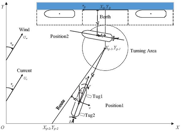
Figure 1 Coordinate systems.
A 3-layer neural network controller was proposed from the above analysis. As shown in Figure 2, the first layer is the input layer which contains 6 nodes: d, u, v, r, and d. On the other hand, the output layer contains 4 nodes: n, , n, n. The number of nodes in the hidden layer is determined from the empirical formulas.
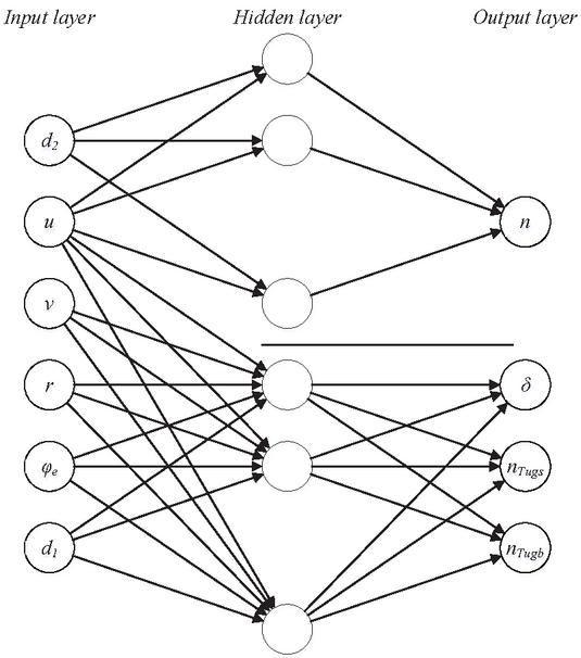
Figure 2 The architecture of the neural network controller.
3.3 Number of Nodes in the Hidden Layer
Due to the lack of a strict theoretical approach, the number of neurons determination in the hidden layer has become a major issue in the designing of network architectures. In addition, the number of neurons in the hidden layer depends on the number of training samples, the size of the sample noise, and the complexity of orders, contained in the samples. In this study, the following formula is used to determine the number of neurons in the hidden layer.
| (10) |
In Equation (10), b is the number of neurons in the hidden layer, b is the number of neurons in the input layer, b is the number of neurons in the output layer, and is a constant from 1 to 10.
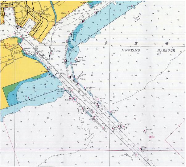
Figure 3 Simulation nautical chart.
3.4 Training Data
As mentioned above, we conducted simulations for the automatic berthing from Berth 31# to 36# in the Jingtang Area of Tangshan Port shown in Figure 3. These berths are assigned as 100,000-ton bulk cargo ships. The training data was directly collected from the direct or turning berthing process in Berth 36# and 37#, commanded by the pilots from the Pilot Station of the Tangshan Port. A scheduled route was set up for each berthing process. The pilot navigated the ship along the scheduled route. During the navigation, the motion parameters, control parameters, and position parameters were collected. A total of 13 ship berthing operations were conducted by the pilots, where 6 operations have produced satisfying results which are further selected as training data in this study. Among 6 operations listed in Table 4, four of them were direct berthing operations, while the rest of 2 were turning and berthing operations. A total of 12263 sets of training data and 2616 sets of verifying data are collected from these 6 operations.
The water area which connects the channel and the turning waters is selected as a starting point for the pilot operation. While the endpoint either Berth 36# or 37#. When the distance from the center of the ship to the berth becomes one time of its width, then the distance from the ship side to the berth is about 20 meters. When the position of the ship satisfies this distance, then it is perceived that the mooring condition has been satisfied. Moreover, the system records by default the end of the berthing operation. The heading direction of the berth is 055. For the turning-berthing operation, the direction of the berth is 235. In each berthing process, the route was set up which connect the starting point and the ending point of the berthing process. During these 6 berthing operations, the ships were strictly navigated through the waters along the scheduled routes. The scheduled routes for each berthing operation are shown in Figure 5. In this figure, the blue dotted lines represent the boundary of the channel and the basin area, while the blue solid line indicates the front line of the berth. The scheduled routes for the 4 direct berthing operations are marked with red solid lines, and the scheduled routes for the 2 turning-berthing operations are marked as green solid lines.
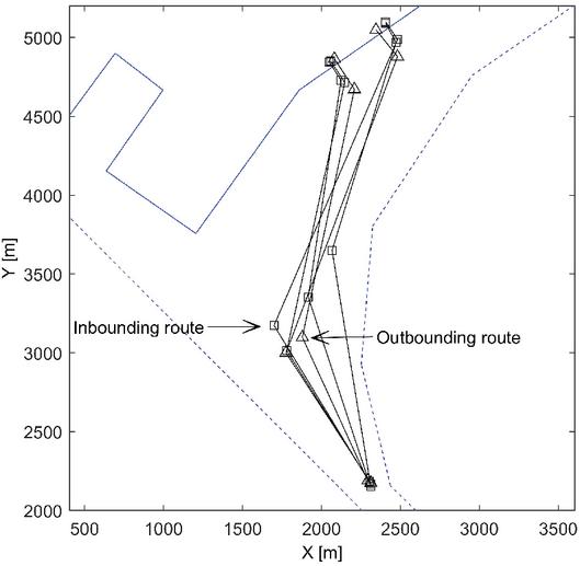
Figure 4 Scheduled routes from the training data.
Table 4 Working conditions of the 6 sets of training data
| No. | Initial Heading | Initial u | Initial v | Berth Number | Turning or Not |
| 1 | 330 | 2 | 0 | 36# | not |
| 2 | 342 | 2 | 0 | 37# | not |
| 3 | 315 | 2 | 0 | 36# | not |
| 4 | 351 | 2 | 0 | 37# | not |
| 5 | 330 | 2 | 0 | 36# | turning |
| 6 | 320 | 2 | 0 | 37# | turning |
Figure 4 is the layer of 6 routes in simulation. The overlap of experimental track results is obtained from the training data as shown in Figure 5(a): the overall figure; (b): the zoom view figure.
During the training process of the neural network, the data of six groups was used as input training data, while the data of Group 4 is used as verifying data to train the network. The Neural Network Toolbox in the Matlab (Version 2010b) was employed to train the neural network. The root means square error and the mean absolute error of the verifying data are listed in Table 5. The weight and threshold of the input layer with the hidden layer are listed in Table 6. On the other hand, the weight and threshold of the hidden layer with the output layer are listed in Table 7.
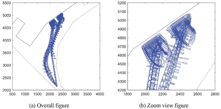
Figure 5 The trajectory of the training data in the ship’s berthing.
Table 5 RMSE and MAE of the verifying data
| n | Rudder Angle | n | n | |
| RMSE | 0.368571 | 0.025423 | 0.351151 | 0.316416 |
| MAE | 0.030841 | 8.48E-06 | 0.006718 | -0.01842 |
Table 6 Weight and threshold of the input layer with the hidden layer
| b | ||||||
Table 7 Weight and threshold of the hidden layer with the output layer
| W | b | ||||||||||||||
| 1 | 0.5 | ||||||||||||||
| 0.3 | 3.3 | ||||||||||||||
| 0.1 | 0.5 | ||||||||||||||
| 0.2 | 0.6 | ||||||||||||||
4 Simulation of Automatic Berthing
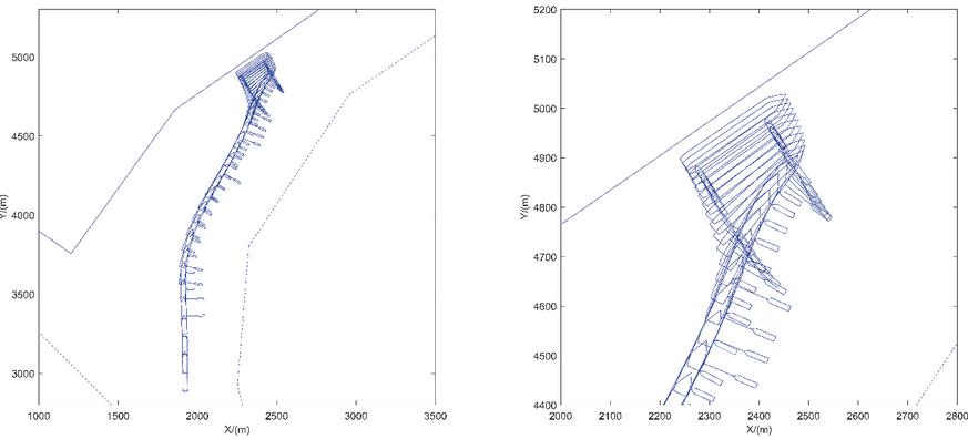
Figure 6 The trajectory of the direct berthing towards Berth 37#.
4.1 Direct Berthing Simulation
In order to verify the effectiveness of the neural network controller, we have employed our designed neural network controller for the simulation of direct berthing and turning-berthing, when the ships berthing into Berth 37#. As we know, the training data already covers the direct berthing and the turning-berthing, the initial heading of the ship is properly adjusted in the verification. The initial heading direction of direct berthing and turning-berthing is set to zero. Each scheduled route is still composed of 3 sections while the third section is the scheduled route for the approaching process of the ships. The trajectory of the direct berthing is shown in Figure 6 while their relevant parameters are shown in Figure 7. Moreover, the trajectory of the turning-berthing and their relevant parameters are shown in Figures 8 and 9, respectively. In Figures 7 and 9, the left part denotes the curve duration of neural network output parameters, and the right part is the curve duration of the neural network input parameters. The main engine order of the pushing or the pulling (by the tugboat output) of the neural network are all integers (the main engine telegraph is 5 to 5; the tug is 4 to 4). On the other hand, the output value of the neural network is not an integer, so, the above three parameters are rounded.
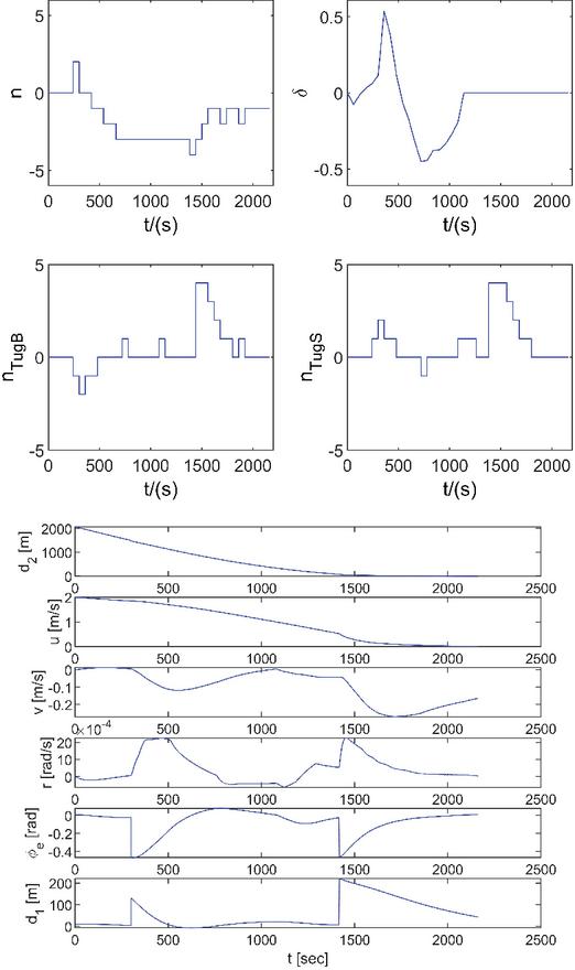
Figure 7 Duration curve of the parameters in the direct berthing towards Berth 37#.
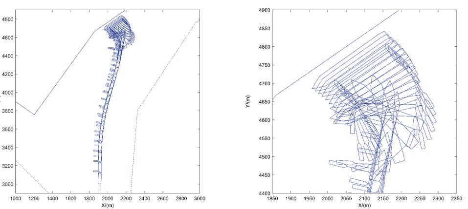
Figure 8 The trajectory of the direct berthing towards Berth 36#.
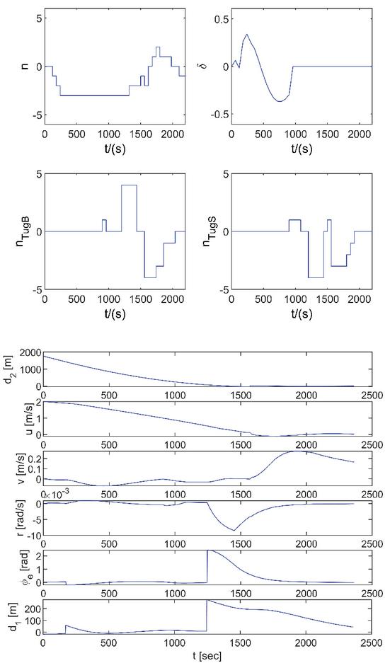
Figure 9 Duration curve of the parameters in turning-berthing towards Berth 36#.
The direct berthing can be observed from Figures 6 and 7, where the trajectory is managed by the neural network controller and is relatively smooth. When the ship approaches the turning area, then it gradually slows down and adjusts itself in the bowing direction. The curve of the forwarding speed of ship u gradually approaches to zero while the parameter d also gradually approaches zero. Comparative analysis of these results led us to conclude that the berthing position of the ship is on the scheduled route and the ship arrives at the target berth. When the final distance of the ship to the berth reaches 43.5 m, then the berthing process complete. The value of the final distance from the ship to the berth is close to 43 which is concluded from the data training. Moreover, this confirms that the results of berthing can easily achieve the goal of automatic control.
The turning-berthing process can be analyzed from Figures 8 and 9, where the trajectory is smoothly managed by the proposed neural network controller. The turning-berthing process starts when a ship approaches the turning area and its speed became reduced. The ship gradually approaches the berth when its bow direction is adjusted. The berthing process completes when the final distance of the ship to the berth reaches 42 m. The value of the final distance from the ship to the berth is close to 43, which conclude that the training data can nicely produce the berthing and meets the goal of the automatic control.
The speed of the ship curves such as u, v, and r gradually approach zero and the parameters d, d and also gradually approach zero. Finally, the ship gains a transverse speed of 0.13 m/s, which satisfy all the requirements of the engineering berthing.
The results of direct berthing of Berth 36# and 37# are shown where the neural network training data used which already contains the direct berthing and the turning-berthing. As long as the neural network architecture is reasonable and has been sufficiently trained, the automatic berthing can be easily achieved.

Figure 10 The trajectory of the direct berthing towards Berth 33#.
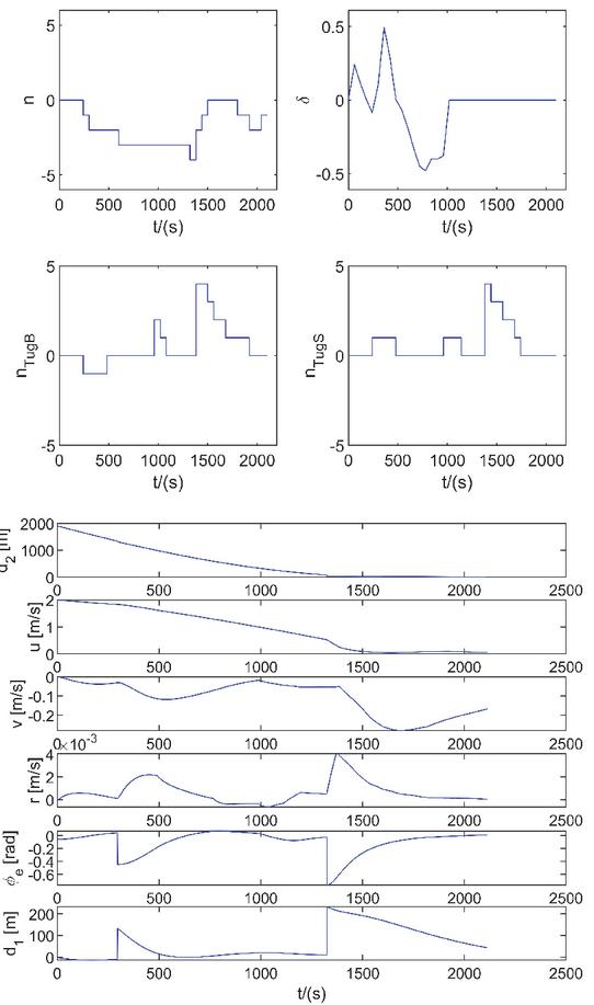
Figure 11 Duration curves of the parameters in the direct berthing towards Berth 33#.
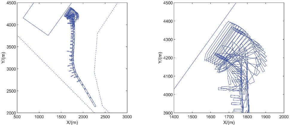
Figure 12 The trajectory of the turning-berthing towards Berth 34#.
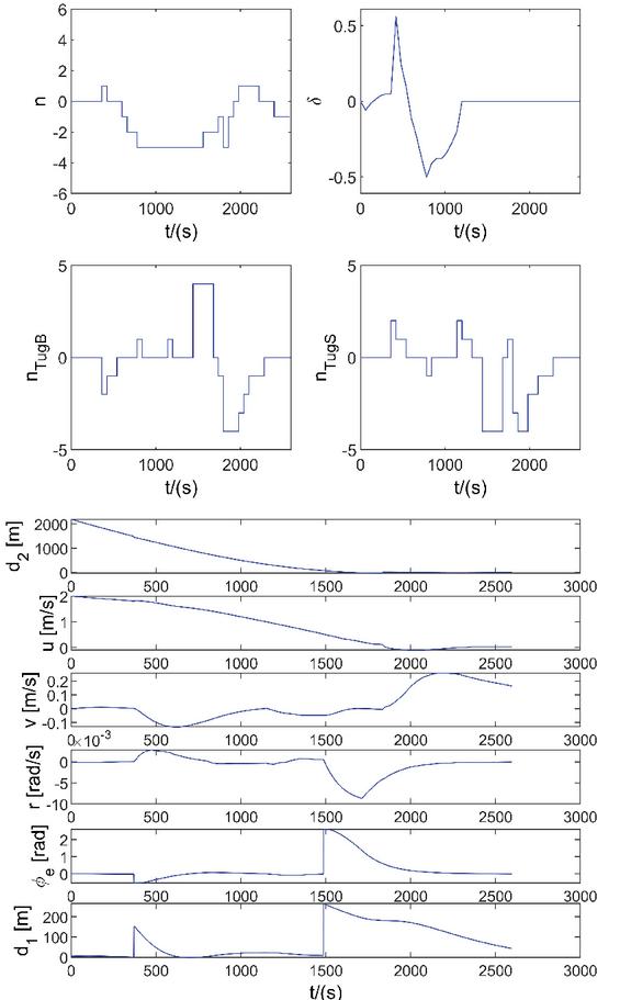
Figure 13 Duration curves of the parameters in the turning-berthing towards Berth 34#.
4.2 Simulation of Berthing towards Berth 33# and 34#
In order to verify the applicability of the neural network controller, we have simulated the berthing process of the ship towards Berth 33# and 34#. These two berths are adjacent to each other, where the training data has been extracted. The only difference between these two berths and the final berthing angle of the training data is 20. The scheduled route is composed of 3 sections, where the last section is the scheduled route of the berthing process of the ship. The trajectory of the direct berthing and its curves along with related parameter are shown in Figures 10 and 11, respectively. The trajectory of the turning-berthing and the duration curves of the parameters are shown in Figures 12 and 13, respectively.
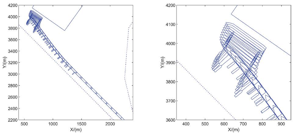
Figure 14 Direct berthing towards Berth 31#.
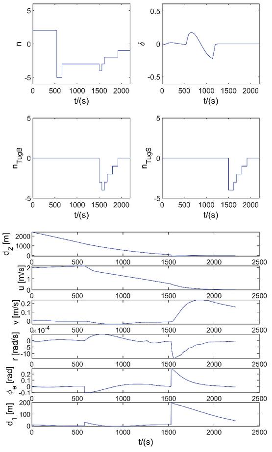
Figure 15 Duration curves of the parameters in the direct berthing towards Berth 31#.
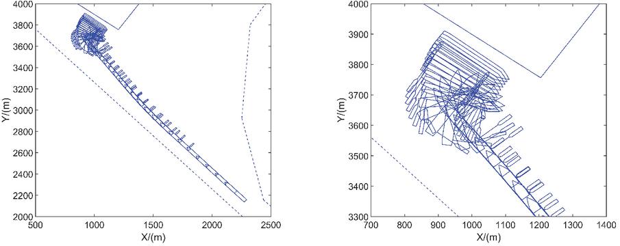
Figure 16 The trajectory of the turning-berthing towards Berth 32#.
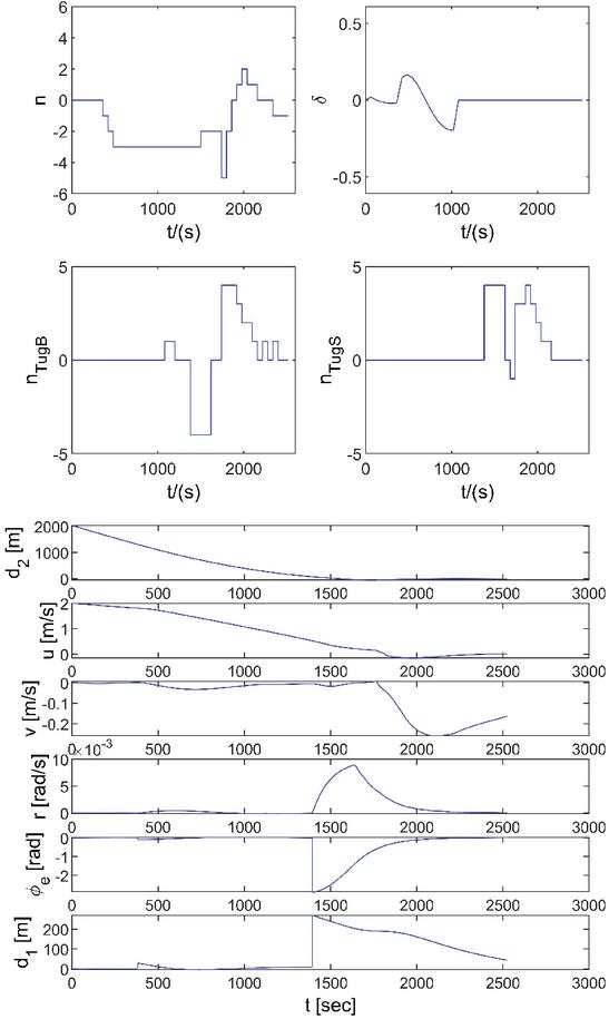
Figure 17 Duration curves of the parameters in the turning-berthing towards Berth 32#.
Analysis of Figures 10 and 12 led us to conclude that the training data does not have the data of Berth 33# and 34#. Moreover, there is a deviation of 20 between the final angle of these two berths and the final berthing angle in the training data. However, our proposed neural network proposed can easily investigate the automatic berthing control of the ship. This indicates that the proposed neural network can complete the control tasks of direct berthing and turning-berthing, when the relative positions of the ships and berths are similar to that of the training data position.
4.3 Direct Berthing Towards Berth 31#
In order to further verify the applicability of our proposed neural network controller, the automatic berthing towards Berth 31# and 32# was carried out, which are in the starboard front direction of the ship. These two berths are different from that of the training data. When a ship directly approaches the berths and is located on the starboard side of the ship, while the berths of training data are collected, which are located on the port side of the ship. So, in case of simulations, the tugboat is placed on the port side of the ship during the direct berthing, while it is placed on the starboard side of the ship during the turning-berthing. The simulation results are shown in Figures 14 to 17. The trajectory of the motion of the ship is shown in Figures 14 and 16. Figures 15 and 17 show the duration curves of the parameters.
It can be observed from these Figures that our proposed neural network control for the scheduled route can still complete the task of automatic berthing of the ship, if the relative relationship between the berth and ship changes significantly. This is attributed to the fact that the scheduled route of the pilot changes along with the relative positional relationship of the ship and the berth, at the scheduled route (already set up). The adverse effects of the variations on the relative position of the berth in neural network control are very serious. Therefore, automatic berthing can be achieved under various conditions.
5 Conclusions
In this study, a neural network control algorithm has been employed for the designing of automatic berthing controller of the ship, followed by the simulation of automatic berthing. The conclusions are as follows:
(1) In our proposed algorithm, the position of latitude and longitude of the ship was neglected. However, other parameters such as distance from the position of the ship to the scheduled route, distance from the position of the ship towards the turning area, and the distance from the position of the ship to the berth’s position were introduced. The repeated training of the neural network was avoided due to the automatic berth control algorithm which is based on the scheduled route. This study predicts that the automatic berthing control of a ship towards various berths is due to the training data which is based on a single berth.
(2) Furthermore, the berthing process of the ship is divided into two stages: the proceeding and deceleration stage, and the turning and berthing stage. These two stages have different control features and ship motion features. We introduced different parameters such as the input of the neural network into each stage, which can smoothly control the main objective of the deceleration, turning, and automatic berthing of a ship.
(3) The design, training, and simulation of the neural network controller along with the automatic control function were conducted with the help of the assistance of two tugboats. In case of multiple tugboats or single tugboats, the appropriate adjustments must be required for the neural network architecture.
Acknowledgment
The authors would like to thank the editors and anonymous reviewers for their valuable comments and constructive suggestions that led to a substantially improved paper. This work is supported by the first-class discipline open research fund of navigation College of Dalian Maritime University in 2019
The Conflict of Interest Statement
As authors of article “Artificial neural network controller for automatic ship berthing using Separate route”, we declare that we have no conflict of interest.
References
[1] L. Trybus, Z. Wider, A. Stec, Tuning rules of conventional and advanced ship autopilot controllers, Advances in Intelligent Systems and Computing, 350(1), pp. 303–311, 2015, http://doi.org/10.1007/978-3-319-15796-2\_31.
[2] Zwierzewicz, Zenon, The design of ship autopilot by applying observer based feedback linearization, Polish Maritime Research, 22(1), pp. 16–21, 2015, https://doi.org/10.1515/pomr-2015-0003.
[3] J.Y. Park, N. Kim, Design of an adaptive backstepping controller for auto-berthing a cruise ship under wind loads, International Journal of Naval Architecture & Ocean Engineering, 6(2), pp. 347–360, 2014, http://dx.doi.org/10.2478/ijnaoe-2013-0184.
[4] N.K. Im, V.S. Nguyen, Artificial neural network controller for automatic ship berthing using head-up coordinate system, International Journal of Naval Architecture & Ocean Engineering, 10(3), pp. 235–249, 2018, http://dx.doi.org/10.1016/j.ijnaoe.2017.08.003.
[5] Van-Suong Nguyen, Van-Cuong Do, and Nam-Kyun Im, Development of Automatic Ship Berthing System Using Artificial Neural Network and Distance Measurement System, International Journal of Fuzzy Logic & Intelligence system, 18(1), pp. 41–49, 2018, http://dx.doi.org/10.5391/IJFIS.2018.18.1.1.
[6] V.L. Tran, N.K. Im, A Study on Ship Automatic Berthing with Assistance of Auxiliary Devices, International Journal of Naval Architecture and Ocean Engineering, 4(3), pp. 199–210, 2012, http://dx.doi.org/10.2478/ijnaoe-2013-0090.
[7] P.H. Nguyen, Y.C. Jung, Automatic Berthing Control of Ship Using Adaptive Neural Networks, International Journal of Navigation and Port Research, 31(7), pp. 563–568, 2007, http://dx.doi.org/10.5394/KINPR.2007.31.7.563.
[8] Yaseen Adnan Ahmed, Kazuhiko Hasegawa, Automatic Ship Berthing using Artificial Neural Network Based on Virtual Window Concept in Wind Condition, IFAC Proceedings Volumes, 45(24), pp. 286–291, 2012, http://dx.doi.org/10.3182/20120912-3-BG-2031.00059.
[9] Yaseen Adnan Ahmed, Kazuhiko Hasegawa, Implementation of Automatic Ship Berthing using Artificial Neural Network for Free Running Experiment. IFAC Proceedings Volumes, 46(33), pp. 25–30, 2013, http://dx.doi.org/10.3182/20130918-4-JP-3022.00036.
[10] Yaseen Adnan Ahmed, Kazuhiko Hasegawa, Automatic ship berthing using artificial neural network trained by consistent teaching data using nonlinear programming method, Engineering Applications of Artificial Intelligence, 26(10), pp. 2287–2304, 2013, http://dx.doi.org/10.1016/j.engappai.2013.08.009.
[11] Yaseen Adnan Ahmed, Kazuhiko Hasegawa, Experiment Results for Automatic Ship Berthing using Artificial Neural Network Based Controller, IFAC Proceedings Volumes, 47(3), pp. 2658–2663, 2014, http://dx.doi.org/10.3182/20140824-6-ZA-1003.00538.
[12] G.Q. Zhang, X.K. Zhang, Y.F. Zheng, Adaptive neural path-following control for under actuated ships in fields of marine practice, Ocean Engineering, 104(1), pp. 558–567, 2015, http://dx.doi.org/10.1016/j.oceaneng.2015.05.013.
[13] X.K. Zhang, G.G. Zhang, Design of ship course-keeping autopilot using a sine function based nonlinear feedback technique, Journal of Navigation, 69(2), pp. 246–256, 2016, https://doi.org/10.1017/S0373463315000612.
[14] Zhang Qiang, Zhang Xianku, Im NK, Ship Nonlinear-Feedback Course Keeping Algorithm Based on MMG Model Driven by Bipolar Sigmoid Function for Berthing, International Journal of Naval Architecture and Ocean Engineering, 9(5), pp. 525–536, 2017, http://dx.doi.org/10.1016/j.ijnaoe.2017.01.004.
[15] H. Yasukawa, Y. Yoshimura, Introduction of MMG standard method for ship maneuvering predictions, Journal of Marine Science & Technology, 20(1), pp. 37–52, 2015, http://dx.doi.org/10.1007/s00773-014-0293-y.
Biographies

Li Qiang is a lecture at Dalian Maritime University since summer 2009. He attend the navigation college where he received his B.sc and M.sc. He has a lot of experience in ship berthing, and is committed to the study of ship automatic control, port tide forecast and so on.

Hong Bi-Guang is a professor of Dalian Maritime University. He received his bachelor’s degree in 1981. He is the first Chinese captain certified by DNV. He has been engaged in the consulting work of port construction for many years, and has made certain achievements in ship network control.
Journal of Web Engineering, Vol. 19_7-8, 1089–1116.
doi: 10.13052/jwe1540-9589.19788
© 2020 River Publishers