Eye Tracking and ROI Detection within a Computer Screen Using a Monocular Camera
Guangmin Sun, Junjie Zhang, Kun Zheng* and Xiaohui Fu
Faculty of Information Technology, Beijing University of Technology, 100 Pingleyuan, Beijing 100124, China
E-mail: eosiyzvbk12959@163.com
*Corresponding Author
Received 09 September 2020; Accepted 25 September 2020; Publication 22 December 2020
Abstract
The region of interest will change according to the task, even in the same situation. In the study, a method for region of interest detection within a computer screen using a monocular camera is proposed. In contrast to gaze tracking techniques that require particular devices (e.g., an eye tracker and RGB-D device) meanwhile complex calibration, a cheap and more convenient monocular camera is used in this study to solves the eye gaze tracking problem. Firstly, Human face is detected in a real-time video sequence using HoG features. Then, the landmarks around the eyes, which reflect the gaze position, are extracted. Next, the iris centers are detected in the eye region. In order to reduce the gaze error caused by head movement, a three-dimensional head model is proposed to estimate head pose. Finally, the eye region is tracked by calculating the eye vectors and head movement. Experiments were performed to evaluate the face detection, landmarks, iris detection, eye movement estimation, and head pose estimation on databases such as the Hong Kong, BioID, and Boston University head pose databases. Besides, experiments for gaze tracking were performed for a real-time video sequence. Deviation is calculated using Euclidean distance between the real and estimated points. The results show that the method achieves an average error of 1.85 with head fixed and 3.58 with head movement in the range of 45 and 45. The requirement is detecting the user’s attention in the screen area. Our method can reach the same level to the other methods, even though the accuracy is not state-of-the-art. Meanwhile, as we all know not only a specific point is concerned but also a region area according to the characteristics of human eye imaging, thus the proposed method can meet the requirements of demand.
Keywords: Iris detection, gaze tracking, monocular camera, ROI detection.
1 Introduction
As computer science and technology continue to develop, the field of human-computer interaction has attracted the attention of an increasing number of researchers because of the ever-changing requirement of human-computer interaction applications. Human-computer interaction technology has evolved from monotonous keyboard and character display interactions to today’s complex and diverse multimedia interactions. Therefore, combined with manual input, human-computer interaction using various media such as gaze tracking and speech recognition has become increasingly popular.
Over 80% of information can be obtained through the visual system. The eye plays an important role in expressing a person’s emotional state, needs, cognitive processes, and other factors. In addition, habits or intention can be determined by what a user is looking at. Therefore, gaze tracking is an important part in the field of human-computer interaction. Using a gaze tracking device to collect the changes in a user’s visual line-of-sight, his or her mental intentions and behaviors can be perceived. These data can reflect the relationship between a user’s eye movement information and his or her choices in thinking and cognition and provide a theoretical and practical basis for psychological and ophthalmology research. Nowadays, some companies and research institutes have developed a series of high-precision gaze tracking systems based on professional equipment. These systems are used in environments such as medical laboratories, assisted driving systems, and classrooms. However, commercial gaze tracking systems are very expensive, which limits their use. Meanwhile, most of the gaze tracking devices on the market rely on active infrared light sources or stereo camera devices, which require specialized hardware support as well as complex hardware parameter and position calibration. They are hence unsuitable for analyzing user behavior in the education and advertising fields. To carry enable gaze tracking to be used more widely, a system that tracks gaze without specialist or invasive equipment can be designed if a single monocular camera is used.
In the study, we propose a method to eye gaze tracking and region of interest (ROI) detection using a monocular camera such as those installed on personal computer. First, human face is detected in the real-time video sequence. Then, regression trees are used to extract eye landmarks. Third, Hough algorithm is used to detect irises in the eye region. In order to decrease gaze error caused by head movement, a three-dimensional 3D head model is adopted to estimate head pose. Finally, the eye vectors and head movement information are used to track eye gaze and detect the ROI.
The structure of this paper is as follows: Section 2 reviews related studies about gaze detection. The methods of gaze tracking are presented in Section 3, including face detection, extract eye features, eye region detection, iris detection, and head pose estimation. In Section 4, we evaluate the proposed method, and Section 5 presents the conclusions.
2 Related Studies
The eye feature is an important part of gaze tracing and can reduce the complexity of feature extraction. Wen and Li [1] performed feature extraction using a CNNs (convolutional neural network) to remove blinking images and predict coarse gaze position. However, it is not convenient to collect a large amount of raw data to train model. Zhang [2] presents a method by using the Canny operator to extract the iris edges, selecting the two longest vertical edges for ellipse fitting to locate the iris centers. However, feature extraction under natural light is affected by illumination changes and the robustness of this system cannot be guaranteed. Valenti et al. [3] computed head pose to reduce eye tracking error. Kasinsi [4] detected face regions using a Haar cascade, but this method is not an effective way to detect faces under varying illumination and side poses. Yiu and Qin [5] combined head pose and eye tracking, but the head movement must remain within a small range. Some researchers use RGB-D cameras to track sight. For example, Sun and Yin propose a head pose estimation method based on 3D facial models [6]. Symmetry plane was used to estimate the pose orientation. A central profile-based 3D face pose estimation algorithm was developed by Pedrycz and Li [7]. In order to conduct the Hough transform in a parameter space, an objective function was defined and they maps the face profile to an accumulator cell. They calculate the accumulator cell and set the maximum accumulator cell as the central profile. Roll and yaw were determined after the symmetry plane had been computed, because the objective function was based on three parameters. The algorithm can detect the nose tip using the detected central profile. Once the nose tip, nose ridge and nose bottom points were determined, pitch angle was estimated. Kong [8] presented a system that head pose can be estimated by using depth information from a simple RGB-D camera. However, an RGB-D camera is more expensive than a monocular camera.
3 Proposed Method
The center of iris and six key points around each eye plays an important part in a face region (see Figure 1). The eyeball moves in the eye socket as user looking at different content on the computer screen. The six key points around each eye can be treated as reference points, and the direction of eye gaze can be reflected by the position changes of iris center in the eyeball. Thus, the gaze vector formed by the iris center and six key points around each eye contains the information of gaze direction, which can be used for gaze tracking. However, it is difficult to detect the gaze vector when the head moves, we cannot get a high accuracy in the estimated gaze location. Thus, the head location should be considered to countervail for the head movement.

Figure 1 Six key points around the (a) left and (b) right eyes: 300-W database was used to train the model [15–17].
There are three phases in the gaze track system, meanwhile eye features and head pose information are considered together to improve the accuracy of the gaze point estimation (see Figure 2).
In Step 1, the face region is extracted from captured webcam video. Then, the eyes in the face region were detected and we extract the eye features and iris centers in the eye region to determine the eye movement information. In Step 2, mapping vectors for the gaze position are obtained. The vectors and iris position that reflect the gaze position from Steps 1 and 2 will be affected by random head movements. To eliminate the influence of head poses and decreases the gaze position error, head pose and eye movements are considered together in Step 3. As a result, precise gaze position can be obtained in a desktop environment.

Figure 2 Gaze position based on three steps.
3.1 Face Detection
The eye area only accounts for a small part of the whole image. It is difficult to detect eyes and extract eyes vectors in the original image, so it is an effective way to improve the accuracy of detection by reducing the detection area. Human face detection is a valid method to reduce the detection area. In 2002, local binary patterns (LBP) was presented for classifying image textures [9]. In addition, LBP texture operator has been widely used in the field of human face detection and recognition. Whereas, LBP features miss the local structure under certain circumstances. In 2004, a cascade classifier algorithm was proposed and Harr-like features was used for human face detection [10]. Since then, many approaches in this area have been based on Harr-like features. However, it takes a long time to train cascaded Harr object detectors (generally hours or days) and false negative rates and many spurious parameters must be tuned. In 2005, Ko presented a human detection algorithm which can reach high detection results [11]. A dense grid of histograms of oriented gradients (HoG) was used in the method, computed over blocks of 16 16 pixels used as a detection window. This representation has proven to be powerful enough to classify humans using a linear support vector machine. The result of human face detection will be influenced by large variation, such as different illuminations, facial expressions, and backgrounds, thus human face detection remains a challenging issue in real world applications. For Shuo-Yang’s Hong Kong database, which contains extremely complicated backgrounds and dramatic illumination changes, the HoG feature achieves a much higher detection accuracy than the Harr-wavelet feature. Moreover, it is easy to train HoG features. We do not have to perform any tedious subsampling or hard negative mining. As for the accuracy, it is easy to obtain the same detection rate as Harr-wavelet features but with thousands of fewer false alarms. Examples of the use of HoG and Harr-wavelet features to detect faces are shown in Figure 3.
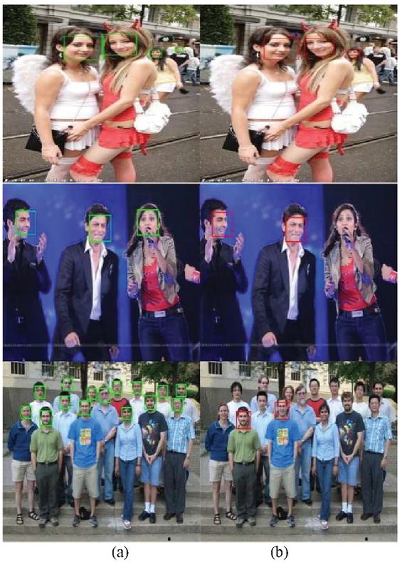
Figure 3 Face detection using (a) HoG feature and (b) Harr features: Hong Kong database was used to test the result of Hog and Harr feature.
Compared with HoG features, Harr wavelets are good at detecting texture features (for instance, whether a target area is bright or dark), but they cannot detect direction features effectively, which makes them less effective at target recognition. In short, HoG features are suitable for describing shapes and Harr features are suitable for describe shading. It is hence better to describe a pedestrian or the shape of a target using HoG features, and in the proposed method, HoG features are used to detect faces.
3.2 Extracting the Features Around Each Eye
The eye region should be located to extract the eye features in the first place. Traditional eye region detection methods cannot get high accurate result in facial with high illumination and moving heads. Therefore, an efficient approach should be employed to overcome the influence of illumination and head movement. Two steps are proposed to detect the eye region.
First of all, a locality sensitive histogram (LSH) [12] is employed to cope with lighting. Unlike other histogram-based methods to eliminate the effects of lighting that count the frequency of occurrences of each intensity value by incrementing the corresponding bin, an LSH is computed at each pixel location and a floating-point value is added to the corresponding bin for each occurrence of an intensity value. Examples of using an LSH to eliminate the effects of lighting are shown in Figure 4, where four images with different situations (facing toward the light and wearing glasses, facing toward the light without glasses, facing away from the light and wearing glasses, and facing away from the light without glasses) have been transformed into images with consistent illumination.
In the second step, regression trees are used to extract eye features. There are 68 landmarks in the face area with different distribution. It will waste time to train all landmarks together, thus we divided 68 landmarks into four parts and train the landmarks respectively:
1. eye region:22 points;
2. check region: 17 points;
3. noise region: 9 points;
4. mouth region: 20 points.
Compared with other method, it will save time by using our method.
In the paper, the 300-W database was used to train the model [13]. There are large variations in the 300-W database, including different subjects, the change of poses, the change of illumination, and occlusions. The locations of the facial points are shown in Figure 5.

Figure 4 Use of LSH to remove the effects of illumination(author): (a) original image, (b) grayscale image, and (c) LSH result.
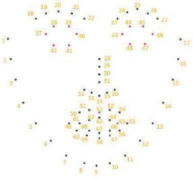
Figure 5 The locations of the facial features.
The facial features can be separated into five parts:
1. check points: from points 1 to 17;
2. eyebrow points: from points 18 to 22 for the left eyebrow and from points 23 to 27 for the right eyebrow;
3. noise points: from points 28 to 36;
4. eye points: from points 37 to 42 and 43 to 48 for the left eye and right eye respectively;
5. mouth points: from points 49 to 68.
Usually, an insensitive facial point to facial expression changes and eye status are selected as reference points for gaze detection, thus the inner, outer, upper eyelid, and lower eyelid points are selected. In the proposed method, eye points are used to reflect the state of the gaze. Examples of eye-point detection are shown in Figure 6. Because the gaze detection system used in a desktop environment, we assume that only one person sits in front of the table. Thus, the Georgia Tech face database [14] was used to test the accuracy of eye feature detection.

Figure 6 Eye-point detection results: (a) Georgia Tech face database[18] was used to test the accuracy and (b) the accuracy was tested in real time.
3.3 Eye Region Detection
Each feature has the same label after the eye features have been extracted. The rule (Table 1) is used to extracted eyes region.
Table 1 The rule to extract eyes region
| Start of left eye region | LeftEyePoint(point (37).x-18, min(point(38).y, point(39).y)-18) |
| width | max(point(41).x,point(42).x)-min(point(38).x, point(39).x)+25 |
| height | point (40). y – point (37). y + 25 |
| Start of right eye region | RightEyePoint(point (43).x-18, min(point(44).y,point(45).y)-18) |
| width | max(point(47).x,point(48).x)-min(point(44).x, point(45).x)+25 |
| height | point (46). y – point (43). y + 25 |
The results of eye region detection can be seen from Figure 7. The pictures in Figure 3.7(a) are from the same database and the pictures in Figure 7(b) were captured in an actual laboratory environment.
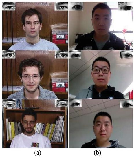
Figure 7 Eye region detection result: (a) images from the Georgia Tech face database [10] and (b) images during actual use.
3.4 Iris Detection and Eye Vector
The center of iris and eye vectors are important features in the eye region, it is useful for us to estimate the gaze direction which can reflect the region of interest.
The iris center should be detected in the eye region after we extract the eye region. For most people, the iris shape is round, thus the circle Hough transform (CHT) [15] algorithm is used to detect the iris in the eye region. The CHT is a specific modification of the Hough transform. The aim of the algorithm is to find circles in noisy image input [15]. A circle can be described in a two-dimensional space is that
| (1) |
where represent the center of the circle and r represent the radius. The parametric representation of a circle is
| (2) | ||
| (3) |
Circle detection using the traditional CHT method has limitations: since the suitable parameters should be selected in three dimensional, a bigger grid size should be considered to solve the problem, it may require large amounts of storage and computation. But it is very difficult to determine an appropriate grid size. To solve this problem, the Hough gradient is used to detect circles. First, any suitable edge detection technique (such as Sobel, Canny, or morphological operations) can be used to find all edges in the image. We draw a circle around each edge point with the desired radius. The illuminate can be seen from Figure 8.
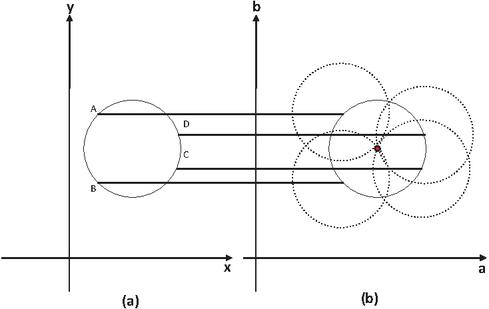
Figure 8 A Circular Hough transformation from the x, y-space (a) to the parameter space (b).
It can be seen from Figure 8 that a value, b value and radii represent x axis, y axis and z axis respectively. It is no longer voting in the parameter space of a complete circle, the gradient vector is calculated at the contour point and then two points were set from the two sides of the contour point distance R in the gradient direction according to the radius of the search field. Finally, the center of the circle can be determined by the voting result. The CHT method can detect more than one circle in the eye region, but just one circle represents the iris. To select the one most likely to belong to the iris, we choose the circle that contains the most black pixels, i.e., the circle for which the sum of pixels within it is minimal. Figure 9 shows the results of iris detection for different situations (wearing glasses, not wearing glasses, facing toward the light, and facing away from the light).
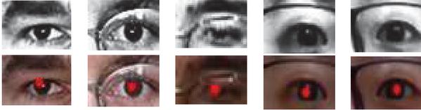
Figure 9 Results of iris detection: (top row) different eye images and (bottom row) detection results.
When a user looks at the different regions on the computer screen plane while keeping his or her head fix (see Figure 10), the iris center I, inner point Einner, outer point Eouter, upper eyelids Eul and Eur, and lower eyelids Ell and Elr is defined as the eye vector, i.e.,
| (4) |
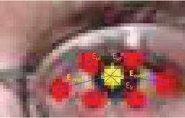
Figure 10 Proposed Eye vector.
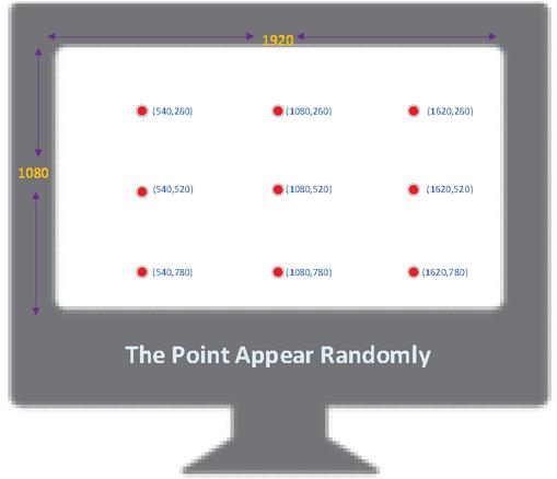
Figure 11 Nine calibration points on the screen (1,920 1,080 pixels).
The gaze information can be reflected by the change of eye vector, thus, we need map gaze direction to screen coordinates using a mapping function. First, the eye vectors should be recorded by the calibration procedure and mapping function needed to calculate the relation between the screen coordinates and eye vectors. There are many mapping functions can be used. For example, neural network [16], SVR [17], and polynomial models [18] can be used. A simple linear model does not yield accurate results, but neural network and SVR models require more calibration data. Thus, a polynomial function had been used to balance the quantity of calibration points and precision. In the calibration stage, each user needed to look nine points appear on the computer screen randomly (see Figure 11). Meanwhile the eye vectors are recorded. Then, the gaze point on the computer screen can be obtained using the polynomial mapping function. Cerrolaze [20] studied the validity and accuracy of polynomial mapping functions by generating a large number of polynomial models with different orders and number of terms. It was found that increasing the order and the number of terms of polynomials leads to almost no improvement in the accuracy of the mapping results. Higher-order polynomial mapping functions require more calibration points. Moreover, it takes a long time to set the calibration time and during the calibration process, it is difficult for the user to maintain concentration. Thus, the following model with a low order and a smaller number of terms is used in the proposed system:
| (5) | ||
| (6) |
where is the point in the computer screen, and denote the eye vector, and least squares method can be used to calculate the parameters and of the mapping function.
| (7) | |
| (8) | |
| (9) | |
| (10) |
It is efficient to calculate the gaze point in each frame by using the mapping function.
3.5 Head Pose Estimation
The gaze error is reduced if the head pose is estimated. In order to determine the posture of the head, the 3D location of the head pose should be projected onto a 2D location (see Figure 12).
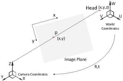
Figure 12 Mapping a 3D point to a 2D point.
To map a three-dimensional point to two-dimensional point, the location in world coordinates should be known. When subjects use the system, they may sit in front of the desk and face the computer; thus, a 3D head model can be created, as shown in Figure 13[20].
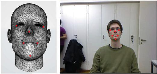
Figure 13 Three-dimensional head model based on the Biwi Kinect Head Pose database [20].
The face orientation is determined by the six points of the nose tip, chin, left eye left corner, right eye right corner, left mouth corner, and right mouth corner uniquely. The matrix of Rotation R and translation T can be calculated using these six points and the corresponding point locations detected in the 2D image as follows:
| (11) |
After the rotation matrix and translation matrix have been calculated, the head pose can be obtained.
4 Experiment
The face detection, eye points detection, iris detection, head pose estimation, and gaze detection were evaluated in this study.
The experimental hardware and development environments are listed in Tables 2 and 3, respectively.
Table 2 Hardware environment
| Hardware | DELL G3 3779 |
| CPU | Inter Core i7-8750H@2.20GHz |
| GPU | Nvidia GeForce GTX 1060 with Max-Q Design (DELL) |
| Intel(R) UHD Graphics 630 | |
| RAM | 8GB (DDR4 2666MHz) |
| OS | Windows 10 64bit (DirectX 12) |
| MONITOR | CMN1738(17.2 inch) 1920*1080 |
| CAMERA | Integrated Webcam |
Table 3 Development environment
| Windows | Version |
| MATLAB | R2018b |
| Visual Studio | 2015 |
| OpenCV | 2.4.13 |
| EmguCV-CUDA | 2.4.10.1940 |
| CUDA | v8.0 |
4.1 Face Detection
In order to obtain eye candidate area, it is necessary to detect the face in the original picture. The accuracy of face detection directly affects the accuracy of eye detection. To evaluate the accuracy of face detection using HoG features and Haar features, the database Faces in the Wild [21], which consists of 30,281 faces collected from news photographs, ORL Face database [22], Yale Face database [23], and Georgia Tech Face database [24] were used. In practice, images were chosen such that the volunteers sat in front of a PC and only one person appeared in the image. All databases except for Faces in the Wild contain images with the same situation, in which each image contains only one person. Different people may sit in front of a PC at difference distances and whether they wear glasses or not may influence the accuracy of face detection. If people sit near the computer or away from the computer, the monocular camera cannot detect the face precisely; thus, the maximum and minimum distance sit in front of the PC was calculated. The images consist of four situations: wearing glasses and facing toward the light, wearing glasses and facing away from the light, not wearing glasses and facing toward the light, and not wearing glasses and facing away from the light. Images were taken in the daytime and in the evening. CEM LDM-100 was used to measure the distances and the results are shown in Table 4.
Table 4 Distances at which the user sat in front of the PC
| Time | Glass | Light | Maximum Distance(m) | Minimum Distance(m) |
| Daytime | Y | Forward | 1.751 | 0.485 |
| Daytime | N | Backward | 0.675 | 0.375 |
| Daytime | Y | Backward | 0.419 | 0.380 |
| Daytime | N | Forward | 1.716 | 0.453 |
| Evening | Y | Forward | 1.175 | 0.375 |
| Evening | N | Backward | 1.825 | 0.414 |
| Evening | Y | Backward | 1.680 | 0.410 |
| Evening | N | Forward | 1.175 | 0.389 |
The proposed method can work in different situations, especially in the daytime when the user faces the light. In most of the strong light contrast situations, such as when the user wears glass and faces away from the light, the proposed method can detect a face if it is a short distance away.
To select the best feature of face detection, all databases were used. Table 5 shows the results of face detection.
Table 5 Accuracy of face detection
| Difference Database | Hog Feature | Haar Feature |
| Faces in the Wild [21] | 72% | 62% |
| ORL [22] | 96% | 71.5% |
| YALE [23] | 96.4% | 27.3% |
| GTFB [24] | 100% | 91.7% |
Figure 14 shows examples of the face detection in all databases.
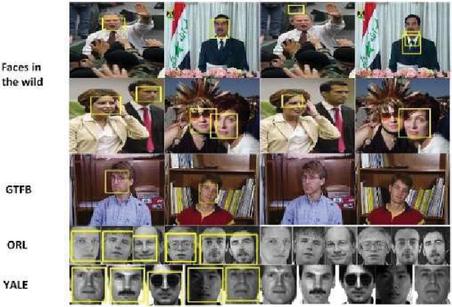
Figure 14 Results of face detection using (a) HoG and (b) Haar features.
4.2 Eye Center Detection
It is an important part to detect the eye center for gaze estimation and the gaze estimation result will be affect by the accuracy directly. The BioID [25] dataset was used to test the accuracy of eye center using proposed method. The dataset consists of 1,521 gray level images with a resolution of 384 268 pixels. Each image shows the frontal view of a face of one 23 different test persons. In certain circumstances, eyes are closed and/or hidden by glasses [25]. The normalized error d was used to test the accuracy [26], calculated as
| (12) |
where is the Euclidean distance between the true and estimated left eye center positions and , respectively, and is the Euclidean distance between the true and estimated right eye center positions and , respectively. In addition, is the Euclidean distance between the true left eye centers and true right eye centers. Table 6 compares the results of the proposed method with those of other methods.
Table 6 Results of iris detection
| Methods | Accuracy | Accuracy |
| Fanelli [26] | 62.00% | 85.20% |
| Gourier [27] | 75.00% | 93.00% |
| Our method | 82.50% | 93.20% |
Figure 3 shows part results of iris center detection on the BioID dataset.
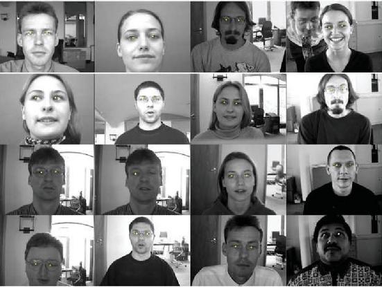
Figure 15 Results of eye center detection on the BioID dataset [25].
From Figure 15 we can see that our method can detect eye centers on right and left eyes in different situations, namely changes in illumination, people in different poses, when more than one person appears in the image, and whether the person wears glasses or not.
4.3 Head Pose Estimation
Thanks to the results of eye gaze will be affected by the accuracy of eye center location and eye vectors, head pose will influence the effect of gaze location. To reduce the gaze error, the head pose is used to correct the eye gaze. The Biwi Kinect Head Pose database [19] and Head Pose Image database [32] were used to test the accuracy of head pose estimation. To test the accuracy in real time, Boston University’s head pose database [19] was also employed in the test.
The Biwi Kinect Head Pose database contains six females and 14 males, and four people were recorded twice. The head pose range covers from 75 to 75 yaw and 60 to +60 pitch. Ground truth is provided in the form of the 3D location of the head and its rotation [19]. Generally, the head pose estimation error is measured using the following equation for the two (vertical and horizontal) angles or three rotation angles (pitch, roll, and yaw).
| (13) |
The Head Pose Image database is a benchmark of 2,790 monocular face images of 15 persons with variations of pan and tilt angles from 90 to 90. For every person, two series of 93 images are available [27, 28].
Table 7 shows the results of head pose estimation for all three head pose databases.
Table 7 Results of head pose estimation
| Rotation Angles | Fanelli [26] | Gourier [27] | Fanelli [19] | Ours |
| Roll | 3.1 | 3.22 | 3.0 | 2.90 |
| Yaw | 5.4 | 5.33 | 6.10 | 5.23 |
| Pitch | 5.6 | 7.22 | 5.26 | – |
To test the accuracy of head-pose estimation in real time, the Boston University dataset was used. The database consists of 45 video sequences, in which five subjects were asked to perform nine different head motions under uniform illumination in a standard office setting [19]. In addition, the dataset consists of two classes of sequence. One set of sequences was collected under uniform illumination conditions and the other set was collected under time varying illumination. Each video sequence consists of 200 frames and shows people moving freely their head. Videos ssm5, vam6, and jim1, taken under uniform illumination conditions, were used to test pitch, roll, yaw result respectively
The change of illumination will influence the result of head pose estimation. To test the robustness, videos jal4, jal8, and ssl6 were taken under time varying illumination to test pitch, roll, yaw result respectively.
The result of the estimated head rotation angles compared with the ground truth is shown in Figure 16.

Figure 16 Results of head pose estimation in the Boston University head pose dataset [24]: (a) head movement under uniform illumination, (b) head movement under varying illumination, (c) estimated pitch, (d) estimated roll, and (e) estimated yaw.
High accuracy is obtained under both uniform and varying illumination. Figure 16(c) shows that it is difficult to measure pitch using only a monocular camera, but the results are right. The pitch result under varying illumination is explained in Figure 17, which shows that depth information cannot be measured using only a monocular camera.
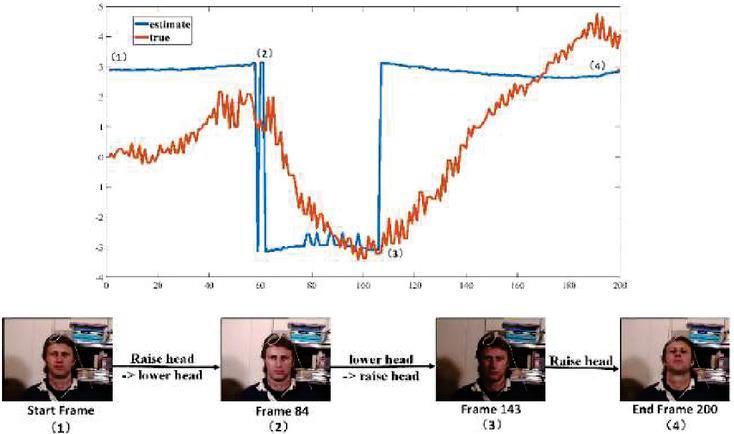
Figure 17 Explanation of the pitch results in Figure 16(c).
4.4 Gaze Estimation
The gaze estimation system was implemented on a desktop PC (see Figure 18). The system utilized an integrated webcam with a resolution of 1,080 720 pixels. The camera was installed at the center of the top of the screen. As for the previous experiments, the details of the experimental environment are listed in Tables 1 and 2. Each user sat in front of the monitor, but they could adjust the distance between the user and monitor in different situations (see Table 3) so that the user’s head was fully captured by the camera clearly. Different people sat in front of the computer in different locations, so calibration was the first step for all users. Nine calibration points appeared randomly on the computer screen and each subject looked at the target point.
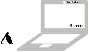
Figure 18 Eye sight detection system with a screen of dimensions 1,920 1,080 pixels.
Performance of the gaze tracking system was evaluated in the following two situations: head fixed and head movement. Formula (14) was used to calculate the accuracy of the system
| (14) |
where is the distance between the estimated gaze position and the real observed position, and is the distance between the subject and the computer screen.
In the gaze tracking without head movement experiments, eight volunteers from our lab, five who wear glasses, participated under different illumination conditions. Users were required to look at different target calibration points on the computer screen and then estimated gaze points were recorded. The distance between the calibration points and gaze points were computed. The estimated gaze points on the screen are shown in Figure 19.
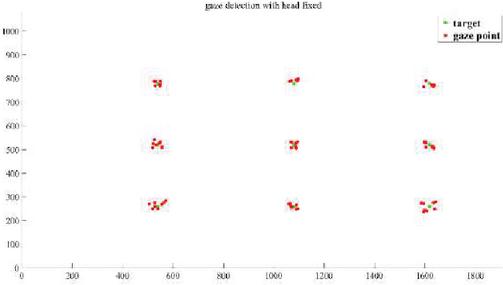
Figure 19 Gaze detection results with fixed head.
Six methods were compared with head fixed.
Table 8 Performance of four difference methods with head fixed
| Method | Accuracy (Degree) |
| Zhu et al. [29] | 1.46 |
| Valenti et al. [3] | 2.00 |
| Lu et al. [33] | 0.97 |
| Cheung et al. [34] | 1.28 |
| Our method | 1.85 |
In the gaze tracking experiments with head movement, the users can move their head randomly while staring at a point on the computer screen. The result can be shown from Figure 20. Compare with head fix, the error of head movement is much larger. The reason why the accuracy decrease is that it is difficult to detect the eye features during head movements in a large scale.
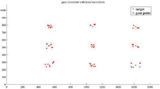
Figure 20 Gaze detection results with head movement.
Five methods were compared with head movement.
Table 9 Performance of five difference methods with head movement
| Method | Accuracy (Degree) | The Degree of Head Movement |
| Torricelli et al. [35] | 2.40 | 15.515.54.1 |
| Valenti et al. [3] | 2–5 | 1615.56.2 |
| Sugano et al. [36] | 4.0 | 11.410.21.1 |
| Lu et al. [37] | 2–3 | 18.215.210.7 |
| Cheung et al. [41] | 2.27 | 15.515.55 |
| Our method | 3.58 | 45450 |
It is known that 80% of information is obtained through sight. Analyzing the visual information obtained by a user can be used to determine a user’s intention and guide his or her behavior. Gaze detection systems are very useful in daily life, especially in driving, advertising, and the classroom. In the field of driving, it can reduce accidents by analyzing the driver’s area of interest while they drive. To test the ROI detection of our method, each subject was required to look at three pictures for 40 s each (see Figure 21) and look a driving recorder video to simulated driving environment (see Figure 22).
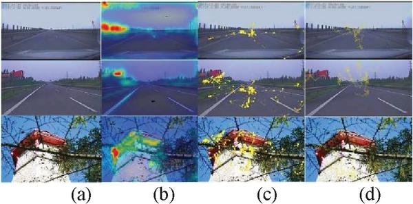
Figure 21 ROI detection: (a) original picture (b) GBVS model results, (c) eye tracker results, and (d) monocular camera results.
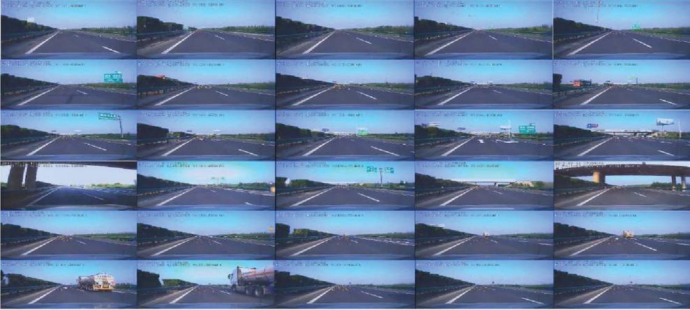
Figure 22 ROI detection in simulated driving environment: the yellow point is the line of sight.
Figure 21 shows that the GBVS model considers the texture information and color information of the image to be the theoretical ROI; however, a driver should pay more attention to the region in front of the car in practice. Thus, the ROI detected by the GBVS model is not suitable in a driving scenario because this scenario is task-driven. The purposes of gaze tracking are simply to know which area the user is focused on, not necessarily a precise coordinate point location. Thus, our system can detect gaze and attention hotspots effectively.
5 Conclusion
A monocular camera installed on a computer can be used to track gaze in a desktop environment. The primary contribution of the proposed method is to extract eye landmarks and use them to find eye centers using the Hough transform. Further, we utilized a 3D head model to estimate head pose. Therefore, the combination of the eye vector was formed by the iris center, inner point, outer point, two upper eyelid points, and lower eyelid points. The system obtains an accuracy of 1.85 without head movement and 3.58 with head movement in the range of 45 and 45. The experimental results hence show that the method is an accurate approach to tracking gaze.
Acknowledgement
This work was partly supported by 2018 Beijing Educational Science Planning (Grant No. CADA18069).
References
[1] B. Li, H. Fu, D. Wen, et al. ‘Etracker: A Mobile Gaze-Tracking System with Near-Eye Display Based on a Combined Gaze-Tracking Algorithm’. Sensors (Basel), 18(5) pp. 1626–1644, 2018.
[2] W. Zhang, ‘Eye gaze estimation from the elliptical features of one iris’. Optical Engineering, 50(4), pp. 047003, 2011.
[3] R. Valenti, N. Sebe, T. Gevers. ‘Combining Head Pose and Eye Location Information for Gaze Estimation’. IEEE Transactions on Image Processing, 21(2), pp. 802–815, 2012.
[4] A. Kasinski, A. Schmidt. ‘The architecture and performance of the face and eyes detection system based on the Haar cascade classifiers’. Pattern Analysis & Applications, 13(2), pp. 197–211, 2010.
[5] Y. M. Cheung, Q. Peng, ‘Eye Gaze Tracking With a Web Camera in a Desktop Environment’. IEEE Transactions on Human-Machine Systems, 45(4), pp. 419–430, 2015.
[6] Y. Sun, L. Yin, ‘Facial Expression Recognition Based on 3D Dynamic Range Model Sequences’. 10(10), pp. 58–71, 2008.
[7] D. Li, W. Pedrycz, ‘A central pro?le-based 3d face pose estimation’, Pattern Recognition, 47(2), pp. 525–534, 2014.
[8] S. Kong, R. Oyini Mbouna. ‘Head Pose Estimation from a 2-D Face Image using 3-D Face Morphing with Depth Parameters’. IEEE Transactions on Image Processing, 24(6), pp. 1–1, 2015.
[9] T. Ojala, M. Pietikainen, T. Maenpaa, ‘Multiresolution gray-scale and rotation invariant texture classification with local binary pattern’, IEEE Transactions on Pattern Analysis and Machine Intelligence, 24(7), pp. 971–987, 2002.
[10] P. Viola, M. Jones, ‘Robust Real-time Face Detection’. International Journal of Computer Vision, 57(2), pp. 137–154, 2004.
[11] B. C. Ko, Son, Jung Eun, Nam, Jae-Yeal. ‘View-invariant, partially occluded human detection in still images using part bases and random forest’. Optical Engineering, 54(5), pp. 053113, 2015.
[12] K. Qian, X. Chen, B. Sun, ‘Compressive tracking based on locality sensitive histograms’. Pattern Recognition, 72(12), pp. 517–531, 2017.
[13] C. Sagonas, E. Antonakos, G. Tzimiropoulos, et al. ‘300 Faces In-The-Wild Challenge: database and results’. Image & Vision Computing, 47(2), pp. 3–18, 2016.
[14] L. Chen, H. Man, A. V. Nefian, ‘Face recognition based on multi-class mapping of Fisher scores’. Pattern Recognition, 38(6), pp. 799–811, 2005.
[15] O. Richard Duda. ‘Use of the Hough transformation to detect lines and curves in pictures’. 15(1), pp. 11–15, 1972.
[16] Eye and gaze tracking for interactive graphic display. Machine Vision and Applications, 15(3), pp. 139–148, 2004.
[17] C. W. Cho, W. L. Ji, K. Y .Shin, et al. ‘Gaze detection by wearable eye-tracking and NIR LED-based head-tracking device based on SVR’. ETRI Journal, 34(4), pp. 542–552, 2012.
[18] C. H. Morimoto, M. R. M. Mimica, ‘Eye gaze tracking techniques for interactive applications’. Computer Vision & Image Understanding, 98(1), pp. 4–24, 2015.
[19] G Fanelli, M. Dantone, et al. ‘Random Forests for Real Time 3D Face Analysis’. International Journal of Computer Vision, 101(3), pp. 437–458, 2013.
[20] G Fanelli, M. Dantone. ‘Random Forests for Real Time 3D Face Analysis’. International Journal of Computer Vision, 101(3), pp. 437–458, 2013.
[21] L. Tamara Berg, C. Alexander Berg, ‘Jaety Edwards, David A. Forsyth’. Who’s in the Picture. Neural Information Processing Systems(NIPS), 2004.
[22] L.L. Yu, X.M. Xia, K.J. Zhou, et al. ‘Affine invariant fusion feature extraction based on geometry descriptor and BIT for object recognition’. IET Image Processing, 13(1), pp. 57–72, 2018.
[23] K. C. Lee, J. Ho, D. J. Kriegman, ‘Acquiring linear subspaces for face recognition under variable lighting’. IEEE Trans Pattern Anal Mach Intell, 27(5), pp. 684–698, 2005.
[24] L. Chen, H. Man, A. V. Nefian, ‘Face recognition based on multi-class mapping of Fisher scores’. Pattern Recognition, 38(6), pp. 799–811, 2005.
[25] J. Wu, Z. H. Zhou, ‘Efficient face candidates selector for face detection’. Pattern Recognition, 36(5), pp. 1175–1186, 2003.
[26] G. Fanelli, ‘Real Time dead Pose Estimation from Consumer Depth Cameras’, International Conference on Pattern Recognition. Springer-Verlag, 6835(1), pp. 101–110, 2011.
[27] N. Gourier, D. Hall, J. L. Crowley, ‘Estimating Face orientation from Robust Detection of Salient Facial Structures’. Fg Net Workshop on Visual Observation of Deictic Gestures, 2004.
[28] N. Salehi, M. Keyvanara, A. Monadjemi. ‘Robust Real-Time Gradient-based Eye Detection and Tracking Using Transform Domain and PSO-Based Feature Selection’. Elcvia Electronic Letters on Computer Vision & Image Analysis, 16(1), pp. 15–32, 2015.
[29] J. Zhu, J. Yang, Subpixel eye gaze tracking, Proc. 5th IEEE Int. Conf. Autom. Face Gesture Recog., pp. 124–129, 2002.
[30] D. Torricelli, S. Conforto, M. Schmid, T. DAlessio, ‘A neural-based remote eye gaze tracker under natural head motion’, Comput. Methods Programs Biomed., 92(1), pp. 66–67, 2008.
[31] Y. Sugano, Y. Matsushita, Y. Sato, H. Koike, ‘An incremental learning method for unconstrained gaze estimation’, Proc. Comput. Vis., 5304(1), pp. 656–667, 2008.
[32] F. Lu, T. Okabe, Y. Sugano, Y. Sato, ‘Learning gaze biases with head motion for head pose-free gaze estimation’, Image Vis. Comput., 32(3), pp. 169–179, 2014.
[33] F. Lu, Y. Sugano, T. Okabe, Y. Sato, ‘Adaptive linear regression for appearance-based gaze estimation’, IEEE Trans. Pattern Anal. Mach. Intell., 36(10), pp. 2033–2046, 2014.
[34] Y. M. Cheung, Q. Peng. ‘Eye Gaze Tracking With a Web Camera in a Desktop Environment’. IEEE Transactions on Human-Machine Systems, 45(4), pp. 419–430, 2015.
[35] R. Valenti, N. Sebe, T. Gevers. ‘Combining Head Pose and Eye Location Information for Gaze Estimation’. IEEE Transactions on Image Processing, 21(2), pp. 802–815, 2011.
Biographies

Guangmin Sun was born in Shanxi, China, in 1960. He received the B.Sc. degree in electronic engineering from Beijing Institute of Technology, Beijing, China, in 1982, the M.Sc. degree in communication and information systems from Nanjing University of Science and Technology, Nanjing, China, in 1991, and the Ph.D. degree in communication and information systems from Xidian University, Xi’an, China, in 1997. He is currently a Professor with the Beijing University of Technology. His current research interests include neural networks and applications, image processing, and pattern recognition.

Junjie Zhang was born in Beijing, China, in 1993. He received his B.Sc degree in 2015 from Beijing University of Technology, Beijing, China. He combined master and doctor degree. He is currently pursuing his Ph.D. degree in Beijing University of Technology, China.

Kun Zheng was born in Hebei, China, in 1977. He received the B.Sc. degree in electronic engineering from Hebei University, Hebei, China, in 2001, M.Sc. degree in Software Engineering from Beijing University of Technology, Beijing, China, in 2006, and Ph.D. degree in Electronic Engineering from Beijing University of Technology in 2018. He is currently an associate professor with Beijing University of Technology. His current research interests include neural networks and applications, image processing, and intelligent education.
Xiaohui Fu was born in Hubei, China, in 1994. She received her B.Sc degree in 2016 from Wuhan University of Technology, Wuhan, China, and M.Sc. degree in 2019 from Beijing University of Technology, Beijing,China.
Journal of Web Engineering, Vol. 19_7-8, 1117–1146.
doi: 10.13052/jwe1540-9589.19789
© 2020 River Publishers