Chirp Spreading Spectrum in Imperfect Environment and Wireless Tree Topology Network
Hongqiang Li*, Dongyan Zhao, Xiaoke Tang, Jie Gan, Xu Zhao* and Yubing Zhang
Beijing Smart-Chip Microelectronics Technology Co., Ltd. Northern Territory Xixiaokou Rd, Haidian district, Beijing 100192, China
E-mail: zhaoxu@sgitg.sgcc.com.cn
*Corresponding Author
Received 13 October 2020; Accepted 06 November 2020; Publication 25 February 2021
Abstract
With the rapid development of IoT technology in recent years, higher requirements have been put forward for wireless communication technology. Low Power Wide Area Network (LPWAN) technology is emerging rapidly, the technology is characterized by low power consumption, low bandwidth, long-distance, and a large number of connections, and is specifically designed for Internet of Things applications. LoRa (Low Power Long Range Transceiver), as a typical representative of LPWAN technology, has been widely concerned and studied. This paper analyzes the performance of LoRa modulation in the tree topology network and analyzes the performance of LoRa modulation in the imperfect environment for point-to-point communication and multipoint-to-point communication. From theoretical analysis and performance simulation, it can be seen that the influence of frequency offset or multipath fading on LoRa signal is very obvious. However, when LoRa modulation is used for networking, multi-user interference will be introduced. Under the influence of many imperfect factors, the signal receiver performance of LoRa modulation will be difficult to guarantee. Because of these effects, Coordinated Multiple Points based on Timing Delay (DCoMP) is presented. Multiple nodes close to each other send the same data to the target node. Due to the inaccurate synchronization between nodes, there will be a certain relative delay when sending signals to the same target node. After the receiving node combines the signals of multiple nodes according to different relative delays, the reception performance of the signals can be improved. At the same time, the cooperative node can also actively adjust the signal sending time to improve the reception performance of the receiving node signal merging algorithm. LoRa modulation, by using DCoMP transmission, improves the reception of signals and thus the overall capacity of the system. Through the analysis of multipoint communication and single point communication, this paper is of great help to LoRa network deployment.
Keywords: LoRa, LPWAN, FSCM, chirp, IoT, DCoMP, Tree topology.
1 Introduction
With the rapid development of IoT technology in recent years, higher requirements have been put forward for wireless communication technology. Low Power Wide Area Network (LPWAN) technology is emerging rapidly, the technology is characterized by low power consumption, low bandwidth, long-distance, and a large number of connections, and is specifically designed for Internet of Things applications [1–3]. LoRa (Low Power Long Range Transceiver), as a typical representative of LPWAN technology, has been widely concerned and studied.
LoRa is one of the technical regimes of LPWAN, which is currently widely used commercially. LoRa is the physical layer technology regime for the LoRaWAN system, whose standards are held by the LoRa Alliance [4]. The LoRa modulation technology patent [5] gives the basic framework of LoRa modulation. Paper [6] gives a general description of LoRa modulation technology and provides some basic equations. Paper [7, 8] gives more details of signal modulation and demodulation technology, but the mathematical and signal processing theory description of signal modulation and demodulation process is still lacking. For the first time, literature [9] provides strict mathematical formulas and signal processing analysis for the modulation and demodulation process of LoRa, and proposes a theoretical derivation of the demodulation process based on FFT with low complexity. The paper [10] analyzed in detail the influence of LoRa signal demodulation by frequency offset. With the increase of SF, the sensitivity of LoRa system to frequency offset becomes higher. The paper [10, 11] analyzes the interference of LoRa modulation under the multi-hop network structure. The paper [13] analyzes the multi-user interference of LORA modulation under the tree topology network.
LoRa modulation is generally considered as a chirp spread spectrum modulation signal [14, 15]. The information carried by LoRa modulation signal is determined by the initial frequency of the symbol, while Chirp can be considered as a carrier. Therefore, LoRa can be considered as a Frequency Shift Chirp Modulation (FSCM) [9]. Paper [9, 10] analyzed the signal characteristics and performance of FSCM modulation. While, this paper analyzes the performance of LoRa modulation in tree topology network, and analyzes the overall performance of LoRa modulation from two aspects: point-to-point communication and multi-points-to-point communication, and then a coordinated multiple points transmission technique with timing delay is proposed, which can significantly improve the system performance without increasing the overall system resource overhead.
Under the tree structure, multiple equipment close to each other sends the same data information to the same receiver equipment. Due to the imprecision synchronization between equipment, there will be a certain relative delay when sending signals to the same receiving equipment. After the receiving equipment merges the signals of multiple equipment according to different relative delays, the receiving performance of the signals can be improved. Meanwhile, the cooperative node can also actively adjust the signal sending time to improve the reception performance of the receiving node signal merging algorithm. LoRa modulation, by using DCoMP transmission, improves the reception of signals and thus the overall capacity of the system. Through the analysis of multipoint communication and single point communication, this paper is of great help to LoRa network deployment.
The rest of this paper has the following structure. In Section 2, the mathematical model of FSCM signal is given, and the orthogonal characteristic of FSCM signal is proved; Section 3 gives the performance of LoRa in the tree network, including the impact of timing offset, frequency offset, and multipath fading channel on performance in point-to-point communication, and multi-user interference analysis in multi-points-to-point communication. Section 4 proposes the Delay CoMP technology and designs the combined algorithm of multiple points. Theoretical analysis and performance simulation prove that DCOMP can improve the system performance. In the end, the paper summarizes the whole paper and gives the prospect of the possible application of this technology.
2 FSCM Signal of LoRa
From [9, 10], assuming that the bandwidth of the transmitted signal is B, the sampling time interval is . The sampling time of a chirp spreading spectrum signal is recorded as . The symbol is a real number formed using a vector of SF bits, and SF is called Spreading Factor, SF in LoRa.
| (1) |
We can see that takes values in .
For any real number , the chirp spreading spectrum signal is:
| (2) |
If , this signal is a basic chirp signal; if , this chirp signal has a different initial frequency, which is why LoRa is called Frequency Shift Chirp Modulation (FSCM).
Suppose
| (3) |
For a time-continuous signal, the FSCM waveform may be denoted as:
| (4) |
From paper [9, 10], we know
| (5) |
For continuous signal
| (6) |
Suppose , the proof process is shown as follows:
| (7) |
Consider that , and
So
| (8) | |
| (9) |
3 Network Communication of LoRa Terminal
LoRa modulation is mainly used in IoT, and the typical network topology in this application scenario is the tree topology network, which is shown in Figure 1.
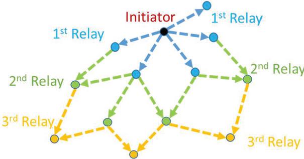
Figure 1 Tree network topology.
The structure includes three types: central node, relay node, and terminal node. From the perspective of the receiving node, the communication types include point-to-point communication, such as the communication between the central node and the lower level node; and multipoint-to-point communication, such as the communication between multiple relay nodes and lower-level nodes. For various types of communication, we need to conduct a detailed analysis.
3.1 Point-to-Point Communication of LoRa Modulation
The point-to-point communication of LoRa node is the communication between one node and another node. Due to the complication of the communication environment, the communication quality will be affected by time offset, frequency offset, and multipath fading, so we need to analyze various imperfect factors
3.1.1 Timing offset of LoRa communication
Assuming that the transmitter adopts constant signal power and the receiver has ideal time-frequency synchronization, the received signal of the nth symbol in AWGN channel is:
| (10) |
, is a Guass white noise with a mean of 0 and a variance .
The best detection of the received signal is to select the appropriate so that its inner product with the received signal is the largest. However, due to the high complexity of the implementation of coherent detection, and theoretically the performance of incoherent detection is 0.8 db lower than that of coherent detection [16]. Therefore, we use the non-coherent demodulation algorithm based on FFT for analysis.
Suppose , then
| (11) |
According to the previous orthogonality analysis, when , the inner product is the largest. For discrete signals, the initial frequency of the transmitted signal can be obtained by Fourier transform, and the information bit sequence can be solved according to Equation (2).
If the received signal contains a certain time offset, the received signal is
| (12) |
,suppose . That is to say, for the sampling point with integer times delay, the demodulation result of the signal can be obtained by the demodulation algorithm as follows. For the sample points containing fractional times, the results can be ignored.
It can be seen that the demodulated bit sequence has become a completely different sequence, so the time offset larger than one sampling chip is fatal to the signal demodulation, which will lead to complete demodulation error. Therefore, LoRa adopts the preamble sequence with a variable length of 6 65535 [4] symbols in the system design to ensure the reliability of time synchronization.
3.1.2 Frequency offset of LoRa communication
LoRa modulation is also called Frequency Shift Chirp Modulation. The bit sequence of each chirp symbol is determined by its initial frequency. One LoRa spreading spectrum signal carries SF bits, so every FSCM symbol has 2SF different waveforms, then the frequency interval between the two adjacent waveforms is B/2. Suppose , then
| (13) |
It can be seen that as SF grows, the frequency interval of adjacent symbols becomes smaller. If the system can effectively eliminate the frequency offset, then the performance will not be affected. Otherwise, if the residual frequency offset exists, its impact on the larger SF will be greater. The system coverage distance will not increase as the SF grows. From Figure 2. If the signal contains a certain frequency offset, then signal C1 will become signal C2, which will lead to demodulation error.

Figure 2 FSCM symbol with frequency offset.
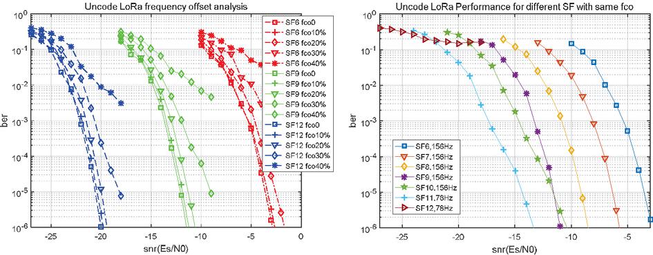
Figure 3 Performance of LoRa with frequency offset.
Figure 3 show the simulation results of Lora signal including frequency offset. When the residual frequency offset is less than 10%, the system performance is almost unaffected; When the residual frequency offset reaches 20%, the system performance deteriorates 1dB; If the residual frequency offset exceeds 20%, the performance deterioration will be significant. Because the frequency interval of the adjacent waveform is , when SF 12, the allowable frequency offset is only 24 Hz, which puts forward very high requirements for the algorithm design of the system.
3.1.3 Multi-path fading channel communication
The fading channel is also a key factor affecting system performance,the multipath fading channel in a typical urban environment is shown in Table 1, and the received signal model is as formula (14).
| (14) |
Table 1 Multipath channel
| Chan-Type | Path | Delay (ns) | Power (dB) |
| \midrule[0.4pt] AWGN | 1 | 0 | 0 |
| ITU PA | 4 | 0, 110, 190, 410 | 0, 9.7, 19.2, 22.8 |
| ITU PB | 6 | 0, 200, 800, 1200, 2300, 3700 | 0, 0.9, 4.9, 8.0, 7.8, 23.9 |
| ITU VA | 6 | 0, 310, 710, 1090, 1730, 2510 | 0, 1, 9, 10, 15, 20 |
Where is the amplitude of the multipath fading signal, is the multipath delay length. Using the same noncoherent detection algorithm, the simulation result is shown in Figure 4.
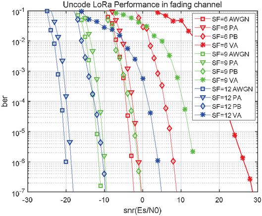
Figure 4 Performance of LoRa in fading channel.
According to the above simulation results, the influence of multipath fading on the demodulation of LoRa signal is very obvious. Compared with the AWGN channel, the performance degradation of the PB channel is about 9 10 dB. When SF 6, the performance degradation of the PB channel is about 10.5 dB compared with the AWGN channel, and when SF 12, the performance degradation is about 9 dB. So with the increase of SF, the system’s ability to resist fading has a certain increase. Similarly, for the VA channel, when SF 6, 9, and 12, the performance degradation is 27.5 db, 24 dB, and 23 dB respectively compared with the AWGN channel. When SF increases, the performance degradation decreases.
Multipath fading and frequency offset will have a very obvious impact on LoRa signal demodulation. To demodulate LoRa signal better, we need to introduce demodulation algorithms such as time-frequency offset estimation, channel estimation, and rake receiver.
3.2 Multi-Point-to-Point Communication of LoRa Modulation
In the tree topology network, the receiving synchronization between nodes is difficult, there are always some timing offset between multiple points under the multiple points transmission. The receiving symbol is shown in Figure 5 and formula (15).
| (15) |
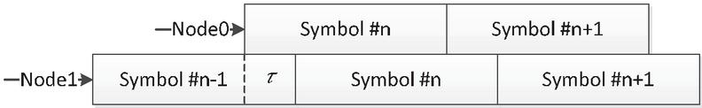
Figure 5 Receiver signals from multiple nodes.
is the timing offset between Node0 and Node1, is the power offset between these two nodes, . For , the system can be regarded as the transmit diversity, the following analysis mainly focuses on .
Calculate the projection of the received signal:
| (16) |
If , then
| (17) |
Because of
| (18) |
So
| (19) |
Denote
| (20) | ||
| (21) |
We get:
| (22) | |
| (23) |
Denote
| (24) |
Then
| (25) |
Denote
| (26) | ||
| (27) | ||
| (28) | ||
| (29) |
Denote
| (30) | ||
| (31) |
For any and , Figures 6 and 7 show their absolute values.
If dB, for any , dB, so
If :
| (32) |
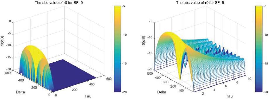
Figure 6 The amplify of .

Figure 7 The amplify of .
So
| (33) | |
| (34) |
Denote
The same, we can suppose that , from the result of Figure 7, when
And then:
If , then
| (35) |
Denote
The same, we can suppose that , when
So
For other cases
| (36) |
Denote
| (37) | ||
| (38) |
Suppose or , when
So we can get that when :
| (39) | |
| (40) | |
| (41) |
The theoretical performance curve of LoRa signal [16] is: If SF is 9, Ber is 10-3, dB. Then for dB. The effect of the interfering signal will be insignificant. This paper mainly analyzes the Node1 transmission power migration of 0 dB, 3 dB, and 6 dB, which denoted as . Suppose , when
For bandwidth 500 kHz, 1 chip 1/500 kHz, the simulation result is shown in Figure 8.
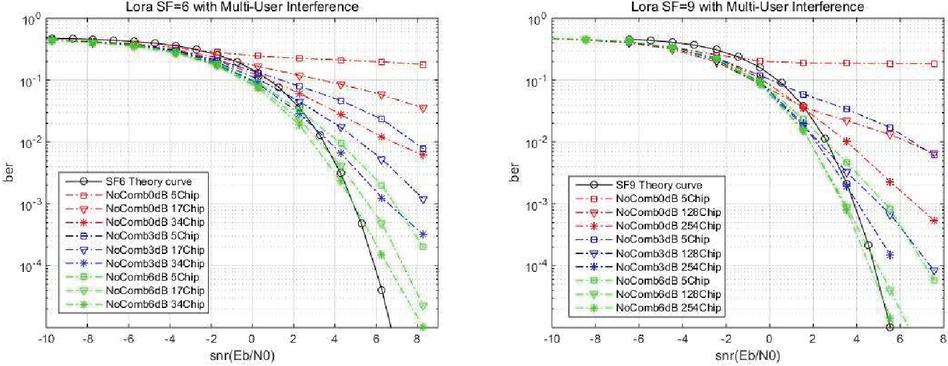
Figure 8 The performance curve under different timing offset interference.
4 DCoMP of LoRa Signal
From the interference analysis in the previous section, it can be seen that multi-user interference has a great impact on system performance. For SF 9, the time offset is 5 chip, the power offset is 0dB, and BER 0.1, with the increase of relative delay, SIR decreases correspondingly. When the timing offset increases to half of the spreading spectrum length, the performance degradation compared to the theoretical curve is approximately 3 dB. If the interference signal power is 3 dB and the time deviation is 5 Chip, the performance deterioration is also very obvious. Even if the delay reaches 128 chip, there is still performance deterioration. If the power of the interfering signal is 6 dB and the time offset is 5 chip, there is still a 2 dB deterioration in performance.
According to the above analysis, to avoid multi-user interference, the signals of two users can only be separated in time-frequency resources. This approach is wasteful of system resources. Because the network architecture of the system is a tree structure, the cooperative multi-point (CoMP) technology can be used. That is, the two transmitting nodes send the same data, and the receiving node combines the signals in the following way.
From Figure 5 and Equation (15):
| (42) |
Receiving merge algorithm is as follows:
Step 1. Compute and
| (43) |
Step 2. Correlated and , from the proof in the last chapter, we can get:
Step 3. Combine the correlation of and :
| (44) | |
| (45) | |
| (46) | |
| (47) | |
| (48) |
Suppose , then
SIR is determined by these two parameters: and . For , this is a transmit diversity. Because synchronization between nodes is difficult to achieve, there is always some time offset between the two nodes. To get better reception performance, the sending time of the signal can be adjusted actively, which is called CoMP technology based on delay (DCoMP). For SF equal to 6 and 9, the simulation results under different delays are shown in Figures 9–11.
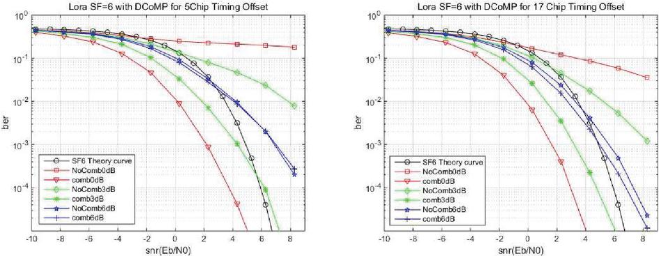
Figure 9
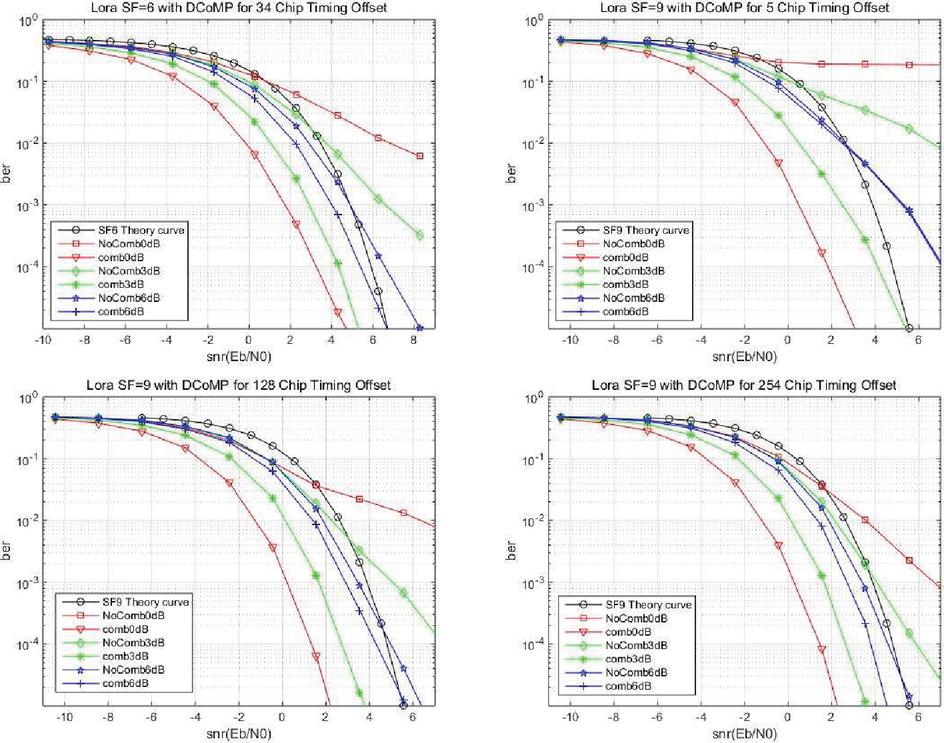
Figure 10 Performance of different delay with and without DCoMP SF 6 and 9.
According to the simulation results, if SF 6, power offset 6 dB, and timing offset 5 Chip, DCoMP technology has little impact on performance. If the timing offset reaches half of the spread spectrum length, DCoMP technology will improve the system performance by about 0.5 dB. If SF 9, we get the same conclusion. If the power offset is 3 dB or 0 dB, DCoMP technology will bring very significant performance improvements. For timing offset 5 chips without DCoMP, we can demodulate the signal at a larger SNR; If the DCoMP technology is adopted, the gain of 3 dB can be obtained. If the timing offset reaches half of the spread spectrum length, DCoMP technology will get a very obvious performance improvement. A performance gain of 2.5 dB is achieved if the power offset is 3 dB, and nearly 7 dB is achieved if the power offset is 0 dB.
On the other hand, if multiple users have the same power offset, different timing offset also has some effect on performance. For SF 6, the performance degradation was greatest with a delay of 5 chips and least with a delay of 34 chips. The same thing happens when SF 9. It can be seen that to obtain the desired reception performance, the signal transmission time of the cooperative node can be adjusted actively. And the adjustment precision does not need to be very high, which brings great convenience to the system design.
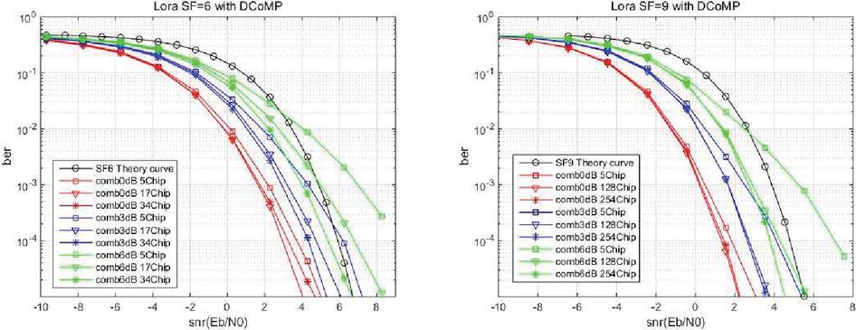
Figure 11 Performance of different delay.
5 Conclusion
From the previous analysis, we can see that LoRa modulation is very sensitive to imperfect factors, such as time offset, frequency offset, and multipath fading. The design of variable length synchronous channels in LoRa communication system can ensure that the system can correct the time offset, but the frequency offset and multipath fading are difficult to resist. Therefore, we need to use a complex frequency offset estimation algorithm, channel estimation algorithm to improve the received signal quality. In the tree topology network, multi-user interference will also have a great impact on system performance, so we propose a cooperative multi-point technology including timing delay to improve system performance.
CoMP has been widely used in LTE. It can improve the quality of the received signal of the target node through the cooperation of multiple base station, and accordingly improve the throughput of the whole system. The DCoMP technology proposed in this paper is slightly different from the CoMP technology of LTE. By introducing different timing delay for multiple nodes, DCoMP can reduce the multi-user interference and improve the signal receiving quality, to improve the throughput of the whole network.
Through the research of this paper, we have an overall understanding of LoRa’s network environment and its performance in this environment, and then we proposed DCoMP technology, which is of great help to the subsequent network deployment.
Acknowledgment
This paper is supported by State Grid Science and Technology Project “Research on key techniques of high speed local wireless communications in electric system” (546816190002).
References
[1] H. Wang; A. O. Fapojuwo, ‘A Survey of Enabling Technologies of Low Power and Long Range Machine-to-Machine Communications’, IEEE Communications Surveys & Tutorials, vol. pre-publishing, no. 99, pp. 1–1, doi: 10.1109/COMST.2017.2721379
[2] M. Centenaro, L. Vangelista; A. Zanella and M. ‘Zorzi Long-range communications in unlicensed bands: the rising stars in the IoT and smart city scenarios’, IEEE Wireless Communications, vol. 23, no. 5, pp. 60–67, 2016.
[3] J. P. Bardyn, T. Melly, O. Seller and N. Sornin, ‘IoT: The era of LPWAN is starting now’, ESSCIRC Conference 2016: 42nd European Solid-State Circuits Conference, Lausanne, pp. 25–30, 2016.
[4] LoRa Alliance, Inc. LoRaWANTM Specification V1.0, January 2015.
[5] F. Sforza, Communication system, Patent US 8406275 B2, Publication date Mar. 26, 2013.
[6] C. Goursaud, J.-M. Gorce, Dedicated networks for IoT: PHY/MAC state of the art and challenges, EAI Endorsed Transactions on Internet of Things, 2015.
[7] B. Reynders, W. Meert and S. Pollin, ‘Range and coexistence analysis of long range unlicensed communication’, 23rd International Conference on Telecommunications (ICT), Thessaloniki, pp. 1–6, 2016.
[8] B. Reynders and S. Pollin, ‘Chirp spread spectrum as a modulation technique for long range communication’, Symposium on Communications and Vehicular Technologies (SCVT), Mons, Belgium, pp. 1–5, 2016.
[9] L. Vangelista, Senior Member, IEEE, Frequency Shift Chirp Modulation: the LoRaTM Modulation, IEEE Signal Processing Letters, 2017.
[10] X. Tang, H.Q. Li, Yubing Zhang, Xu Zhao, ‘Performance Analysis of LoRa Modulation with Residual Frequency Offset’, IEEE 4th International Conference on Computer and Communications (ICCC), Chengdu, pp. 835–839, 2018.
[11] C.H. Liao, G.B. Zhu, D. Kuwabara, M. Suzuki, ‘Multi-Hop LoRa Networks Enabled by Concurrent Transmission’, IEEE Access, 2017.
[12] G.B. Zhu, C.H. Liao, M. Suzuki, Y. Narusue and H. Morikawa, ‘Evaluation of LoRa Receiver Performance under Co-technology Interference’, 2018 15th IEEE Annual Consumer Communications & Networking Conference (CCNC), 2018.
[13] H.Q. Li, Y.B. Zhang, X. Zhao, X.K. Tang, ‘Delay CoMP of LoRa Modulation in Wireless Tree Topology Network’, IEEE 19th International Conference on Communication Technology, pp. 1007–1014, 2019.
[14] M. R. Winkler Chirp signals for communicstions WESCON Convention Record Paper 14.2, 1962.
[15] C. E. Cook Linear FM signal formats for beacon and communication systems, IEEE Trans on Aerospace and Ele. Sys., vol. 10, pp. 471–478. July 1974.
[16] John G. Proakis, Masoud Salehi, Digital Communications (Fifth Edition), Publishing House of Electronics Industry, 2017.
Biographies

Hongqiang Li received his B.Sc. and M.Sc. degrees in Applied Mathematics from Xi’an Jiao Tong University. He has engaged in mobile communication research at Datang Mobile Corporation since 2006. He, as a senior physical layer algorithm engineer at Spreadtrum corporation since 2011, has acquired a solid experience in communication chip design. Hongqiang is currently focusing on Internet of Things technology research at Beijing Smart-Chip Microelectronics Technology Co., Ltd.

Dongyan Zhao received her master’s degree in engineering from Shanghai Jiao Tong University in 1998. Now she is a senior engineer at the research level and her main research direction is integrated circuit design and application. She currently serves as executive director of Beijing Smart-Chip Microelectronics Technology Co., Ltd.. She is a national candidate of “Millions of Talents Project”, an expert enjoying special government allowance of the State Council, and a doctoral supervisor of Shanghai Jiao Tong University. She has granted 54 patents and published 77 papers and 6 books.

Xiaoke Tang received the B.S. degree from the Northern Jiao tong University, China, in 2000. He engaged in smart grid internet of things chip and domestic CPU research and development. His research interests include domestic CPU, carrier communication, low-power design, security algorithm. He has published 20 technical papers and over 20 patents in the area of analog integrated circuits.

Jie Gan received her master’s degree in testing and measuring technology and instruments from Beijing Institute of Technology. She is a general manager assistant of Chip Design Center at Beijing Smart-Chip Microelectronics Technology Co., Ltd., and a backbone member of “smart grid key chip security technology research team” of State Grid Corporation of China, and an excellent expert reserve of State Grid Information & Telecommunication Co., Ltd, and a member of Chinese Association for Cryptologic Research.

Xu Zhao received the B.Eng. degree from the Huazhong University of Science and Technology, Wuhan, China, in 1998 and the M.Sc. degree from Queen Mary, University of London, London, U.K., in 2005, and the Ph.D. degree from University of Edinburgh, Edinburgh, U.K. in 2010. He is currently working with Beijing Smart-Chip Microelectronics Technology Co., Ltd.. His research interests include power line communications, wireless communications and signal processing.

Yubing Zhang graduated from the Department of Radio Engineering of Southeast University, received his Ph.D. degree from the School of Information Engineering of Beijing Institute of Technology in 2005. In 2016, he became a senior engineer, whose research interests include wireless communication, Internet of Things, communication chip design, etc., and he has been working in Beijing Smart-Chip Microelectronics Technology Co., Ltd. since 2018.
Journal of Web Engineering, Vol. 20_1, 191–216.
doi: 10.13052/jwe1540-9589.20110
© 2021 River Publishers