A New Semi-Automated Method for Service Identification
Shahrzad Hekmat1, Saeed Parsa2,* and Babak Vaziri1
1Department of Computer Engineering, Central Tehran Branch, Islamic Azad University, Tehran, Iran
2Department of Computer Engineering, Iran University of Science and Technology, Tehran, Iran
E-mail: Shahrzad.hekmat@gmail.com; parsa@iust.ac.ir; vaziribabak@gmail.com
Corresponding Author
Received 11 November 2020; Accepted 15 November 2021; Publication 12 February 2022
Abstract
Service identification plays a key role in the design of service-oriented systems. There are non-model-based and model-based methods for extracting services from business processes. These methods suggest a set of mostly descriptive solutions that do not pay sufficient attention to service design guidelines and the conceptual relations between tasks. The challenge is to develop an algorithm to automatically identify services from business processes to simplify the analysis and reduce the gap between information technology and business needs. In this paper, we develop a semi-automated service identification method that addresses this gap. This method incorporates the Goal, Data, and Business Process Models (BPM) to identify services based on related tasks, shared data, and business requirements. It advances previous methods by simultaneously considering both semantic and structural relations between tasks which permits better and more accurate identification of services. Moreover, the proposed method considers the principles of service design such as internal cohesion of service methods, loose coupling of services, and reusability of the identified services.
Keywords: Business process model, model-driven method, service identification, software engineering.
1 Introduction
In recent years several methodologies for developing service-oriented systems from business models have been introduced [1–3]. These methodologies, which comprise model-driven and non-model-driven approaches, underlie various mechanisms for identifying services and are different concerning their identification strategies, techniques, inputs, and outputs [4, 5]. The primary focus of non-model-driven methodologies is on the Information Technology (IT) aspect of Service Oriented Architecture (SOA). They suffer from complexity due to a lack of using models in a different phase of the software development process. For example, it is difficult to find certain structural or conceptual relations between business tasks, when most activities in these methodologies are descriptive and depend on different analyzers’ decisions. They also have other shortcomings. First, these methodologies do not offer a clear strategy for extracting IT technical components from BPM models [6]. Second, they pay little attention to the business modeling phase, and thus, their extracted services do not fully encapsulate business requirements. Third, they adopt a non-automative approach that takes manual analytical steps to identify services [7]. All these shortcomings lead to hardly achieving reuse ability, high cohesion and loose coupling between methods of identified services. To further improve these methods, the model-driven approach was introduced [3, 8, 9]. This approach benefits from Model Driven Architecture (MDA) and uses models in different software development phases; applying models in the software development process decreases the complexity. One of the reasons is that it increases abstraction. In addition, by Converting models to each other during the software developing phases, the implementation phase would be easier. Despite having benefits, however, using this approach is also associated with some challenges. For instance, these methods were criticized for paying insufficient attention to business activities, entities, shared resources, and relationships between tasks in service identification that play a pivotal role in software services [3, 8, 9]. Additionally, the lack of sufficient automation of such methods to identify the relationship between services’ method and their primary focus on the development of service-oriented systems through manual and descriptive-analytical techniques results in a heavy reliance on the experience of business analysts [10]. Moreover, although using models in this approach causes paying more attention to the service design principles in some areas such as reuse ability, it still is not enough [2, 11]. These models have also been criticized for not adequately considering semantic relations between tasks. Recently, a few automated and semi-automated methods have been developed to overcome these problems. However, given that highly automated services cannot accommodate capture all the details of business processes and service design principles, these solutions did not ideally resolve the problems [8, 12, 13].
One solution to tackle the abovementioned challenges has been to adopt the Business Process Modeling Notion (BPMN) as a universal modeling language. Accordingly, identification of activities with some similarities such as having common goals and grouping them in a service category by decomposing processes was suggested [11, 14–18]. Considering the instrumentality of this approach in identifying services, we followed and extended it to other analogous cases.
The purpose of this paper is to provide a semi-automated method for service identification in service-oriented systems. Considering software business services instead of business services alone, attention to the criterion of reuse, high cohesion and loose coupling features of identified services; also, the simultaneous use of goals, entities and business processes to identify structural and conceptual relations between tasks which leads to better identifying services. All of these, are the advantages of our proposed method over similar methods. Thus, in a real study, we express this fact.
We have developed a semi-automated method that considers the relations between tasks and resource sharing criteria, such as data, as a basis for detecting services. Here, semi-automated means that most part of the identification process is done automatically by applying proposed algorithms. Therefore, needs for expert intervention and the descriptive solution is decreased. In addition to structural relations, our method identifies semantic relationships between tasks and between tasks and entities. Although there are many definitions for a semantic relationship, we consider it as follows in this paper. Two tasks are semantically related when both address a common goal. Tasks can also be semantically related when they have access to a common entity.
In our method, we assume that there is no software system in the organization or, at least, it is not used to identify services. This assumption is inspired by the top-down view that according to [36], it is a typical approach in service identification. Following the approach, tasks and related business processes have a crucial role in identifying services. Therefore, we need to better understanding them. To do this, first, the As-Is model is used for understanding the processes and related tasks; Then, the To-Be model is used for identifying potential tasks for software services.
The remaining parts of this paper are organized as follows: Section 2 provides a literature review. In Section 3 the proposed method is described in two phases. In the succeeding section, we compare our method with state-of-the-art service identification baselines based on the criteria introduced by some previous studies [19, 20]. We close the article with a brief conclusion.
2 Related Works
Our review of the business process-based approaches that employ BPMN to service identification reveals that despite having significant advantages, there are some challenges to be overcome [10, 21, 22]. In some of these methods, BPMN models are decomposed to separate tasks. These tasks are categorized in different clusters by applying clustering techniques and each cluster introduced as a service [10]. Although loose coupling and high cohesion between tasks as structural relations are considered, ignoring other tasks dependencies such as semantic relations can be challenging. In addition, services are identified from As-Is model instead of To-Be model. Applying heuristic algorithms on BPMN model is another approach to service identification [21]. This method identify services base on semantics analysis of the business rules, requirements and syntax analysis of the processes [21]. This approach is not automated and does not provide detailed information about the heuristics and identified services [21]. The approach presented in [21] is further improved in [22]. However, even the improved version does not pay enough attention to the role of data and requirements in service identification. Moreover, the lack of granularity and automation is considerable.
In references [23, 24], conversion rules are applied to map BPMN’s decomposed tasks to legacy source code to identify services. In these methods, some mapping rules are created for automatic service identification. However, there is insufficient attention to service design principles such as loose coupling and high cohesion [25]. Furthermore, structural relations between tasks have been prioritized over semantic relations.
In model-based and business process-based approaches, our review showed some challenges too. For example, Minerva [11] is a model-based and service-oriented framework that uses an analytical and semi-automatic approach to identify services as collaborative tasks in BPMN models. In this method, each process is divided into sub-processes and the services are extracted analytically and manually from these sub-processes. This method was extended by [2] who suggested a set of conversion rules that transform the BPMN language meta-model into Service Oriented Architecture Modeling Language (SoaML). This model, however, suffers from the lack of consideration of the relationships between tasks, between tasks and goals and insufficient attention to resource sharing among the tasks. Similar to [2], authors in [26] developed a method that accomplishes the same task through a different set of rules. This method advances a part of the Minerva framework. In [3], a model-driven methodology is proposed that takes a different approach. This methodology follows the principles of OMG (MDA) modeling architecture and equates the business model to the CIM level. It also equates to the service-oriented architecture model and the PIM level. In this approach, service-oriented architecture is described from three perspectives: service view, information view, and process view. To map the business model to the service model architecture, it defines a meta-model which includes a set of conversion rules. The disadvantages of this method developing a service-oriented system from business models are just employing conversion rules and not taking into account the semantic relation between tasks, the shared resource and the principle of service design. In addition to the methods mentioned above, there are some semi-automated and automated approaches to identify services related to our research domain. For example, the spanning tree calculates the relation between tasks and determined service elements. However, as the greedy algorithm is used to service identification, the result may not be optimal [12]. ASIM is another way to identify services that use entities to extract a service model from the business model. Lack of considering other dependencies between tasks such as goals and shared resources and semantic relations is the problem [8]. Also, in [27], a semi-automated method is introduced for service identification. This method is based on data flow between tasks and does not attend to task connections.
Our review of the literature reveals that activities, interactions and common goals between them in BPMN models can be an important criterion for identifying services that have not been considered enough yet. Moreover, there has been insufficient attention to the semantic relation between activities through shared resources like data. Besides, some of the approaches present general mapping rules to convert BPMN models to service-oriented based models while identifying services requires more processing on business model components to achieve service-oriented principles such as high cohesion between tasks of a service, loose coupling between the tasks of different services as well as the reusability of services in different processes.
In sum, it is evident that none of the previously developed methods has simultaneously considered goals, business processes and business data in identifying services despite their importance. Furthermore, since these methods, services are identified only by using conversion rules, structural relations between tasks have been prioritized over semantic relations [23–25]. We, therefore, need a more comprehensive solution to address these gaps which is what we offer in the remainder of this paper.
3 The Proposed Method
In order to solve the challenges were mentioned in the previous section, we present our semi-automated method which includes two phases of business modeling and service identification. Following the model-based structure, in each of the two phases, we introduce some models of business and service types.
The business type includes models that capture business requirements without taking into account the software and system needs. This category includes three models of business goals, business data, and the existing business processes (As-Is).
The service-type models complement the business-type models by capturing the requirements and the architecture of the software system. They, however, do not consider the implementation details. The category of service-type models in this method includes two models: the To-Be business processes, software requirements. Table 1 illustrates the two phases of our method, their inputs, and outputs.
In addition, we identify services by considering data, business and goals view synchronously. To make a connection between these different views, three task-task communication matrices are introduced as a common language. The first one indicates the relation between tasks base on their effect on common data. Using this matrix helps to figure out the conceptual relationship between tasks. This, partially solves the related challenges about not paying enough attention to sematic and conceptual relations between tasks. The second, presents the structural relationship between tasks in the business model. By considering this matrix the challenge of insufficient attention to structural relation between tasks is overcome. Finally, the sum of these matrices will be used to identify services and shows the rate of relation and cohesion between tasks which includes different aspect of service identification strategies. Here, cohesion means when tasks are related to each other by addressed same goals or access to the same data.
Table 1 The general scheme of the proposed method
| Phase | Inputs | Outputs |
| AS-IS model | ||
| Business Modeling | Business goals | |
| Business data | ||
| Identify Services | AS-IS model | To-Be model |
| Business goals | Software Requirement | |
| Business data | Software Services (base on software requirement) |
4 Phase One: Business Modeling
In the business modeling phase, we draw on three models: goal, As-is business and data, which are explained below. To better understanding of these models, let’s consider the Judicial System as a case study. Since the duty of most service-oriented applications is to facilitate inter-organizational interactions, the case study should include the interactions of different organizations and departments. Various organizations are also involved in the judicial system, including the court, the prosecutor’s office, the registration of documents, the intelligence, the police, and the prison.
The goal is to identify services in the organization by considering the top-down approach [35]; which means that no software system exists in the organization and all works are done by staff. So, we should develop a service-oriented mechanized system to cover the activities. The duty of this system is to investigate criminal and legal complaints and in this study, only “criminal complaint review” processes are used as an example of motivation. Activities in this process take place and divide into two parts. First, prosecutors’ office which contains determine dictum and preliminary research work flows. Second, the court which supports issue verdict workflow. It is necessary to mention that issuing a verdict is done in court considering the result of preliminary research and determining the dictum from the prosecutor’s office workflows.
Adopting these models needs to follow a specific sequence.
4.1 Creating a Business Goal Model
The function of each organization is typically guided by the goals of that organization. In the Goal model, the objectives of the organization are demonstrated on a multi-level chart with the highest level including major and broad goals and the lowest level presenting detailed business requirements [28–30].
To create this model, we employ the requirements chart in the Visual Paradigm tool. Developing the goal model can be achieved through different methods. What matters to us here are the result and not the method; Therefore, we chose the simplest method which is introduced in [30] and provides us with the outcome. Accordingly, goals divided to subs goals from highest level to the lowest level by using AND or OR relations. Finally, at the lowest level, operational requirements are determined [30].
We use the goal model for three purposes. First, it helps to refine business processes in the identification step. Second, by shedding light on the goals and objectives, it facilitates the identification of tasks that are in alignment with each goal. These tasks constitute services that we intend to identify automatically.

Figure 1 Judicial system’s goal model.
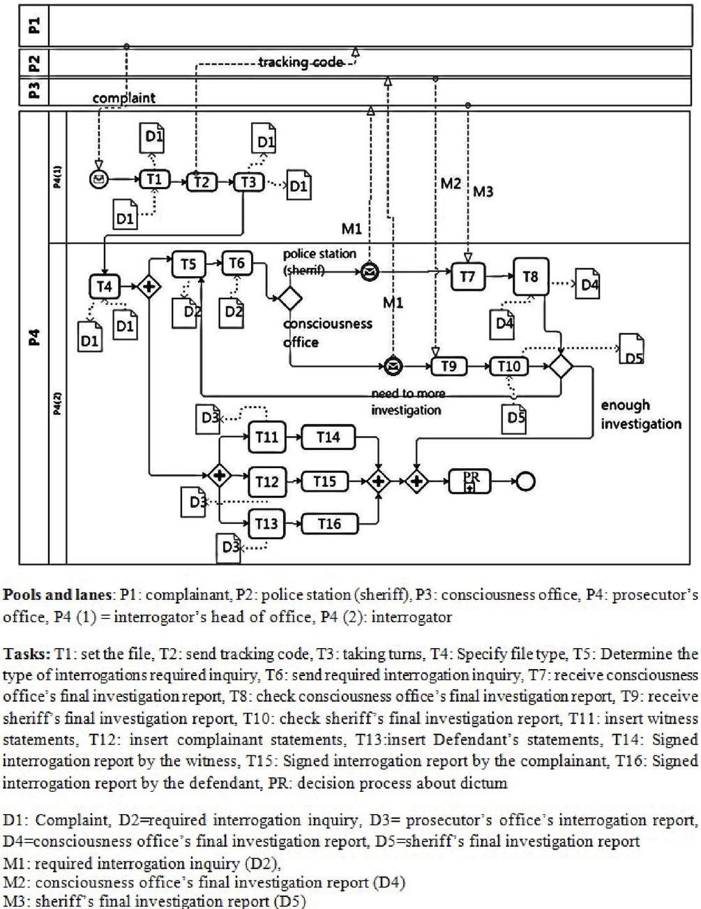
Figure 2 The As-Is model for the preliminary investigation process for a criminal case.
4.2 Modeling Existing Business Processes (As-Is)
To construct the AS-is model of business processes, roles and tasks should be determined. The organizations’ internal roles which are depicted by lanes in the BPMN chart, can be extracted from the organizational chart. The Text chart provides information that assists with the identification of BPMN pools. Whereas for determining the internal tasks the operational chart is used. The text chart is applied for extracting data flows between organizations. These data flows include exchange messages between organizations which are illustrated by messages exchanged between pools in the BPMN diagram. The As-Is diagram for two processes of “preliminary investigation process for a criminal case” and “issue verdict process for a criminal case” are depicted in Figures 2 and 3. and provided by the expert organization analyzer.
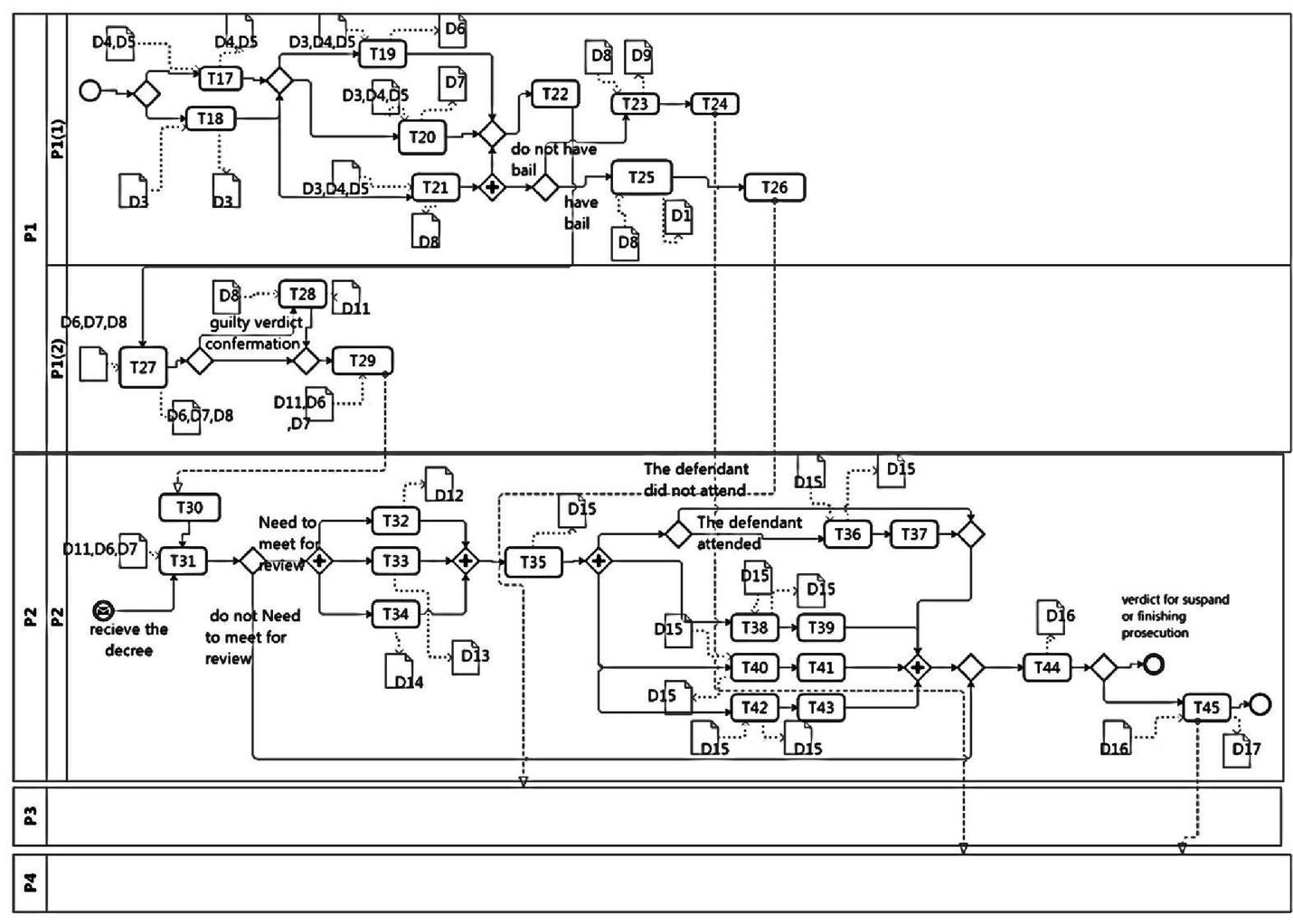
Figure 3 The As-Is model for issue verdict process for a criminal case.
4.3 Modeling Business Data
Following a single data structure is one of the most important prerequisites for the cooperation of services. This enables providers and users to have a common understanding of the information that they want to process and exchange data more easily. Therefore, in this step, a business data model is employed to provide a data structure that can be used in all phases of service-oriented application development. The main components of this model are entities. An entity is a construct that encapsulates a set of attributes and operations that revolve around a key concept. The operations are divided into four types: Create, Read, Update, and Delete data (CRUD).
To define entities and their relationships class diagram is used which provides a high-level view of available information [31]. The data model of the Judicial System is shown in Figure 4. Furthermore, to support the CRUD operations of these business entities, entity services will be defined in the service identification phase.

Figure 4 The “judicial system” business data model.
5 Second Phase: Identification of Services
A combination of the goal, To-Be business process, and business data model are used to identify the service [32]. This work aims to extract both conceptual and structural relations between tasks to determine more accurate services. In our work, we consider semantic relations from this point of view: Two tasks are semantically related when both address a common goal; Also, when they access a common entity, we consider a conceptual relation between them. Increasing the degree of cohesion among the methods of each service and loose coupling connection between different services are the other purpose of our work.
The service identification phase is completed in eleven steps as follows.
5.1 Extracting Software Requirements
In this step, the software requirements are derived from the last level of the extended business goal model which was created in the business modeling phase. These requirements constitute a sub-model which we label as a requirement model. This sub-model, which is applied in the judicial system is depicted in Figure 5, will be used in future steps to identify candidate services and assures the coverage of the business requirements.
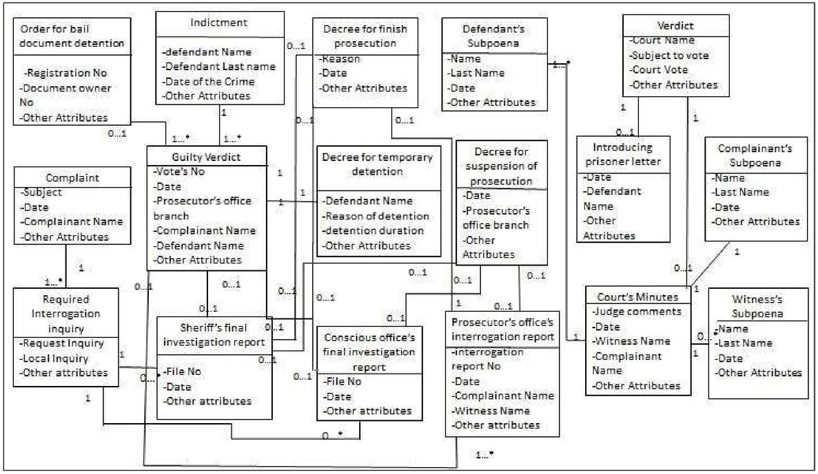
Figure 5 Software requirement model for judicial system.
5.2 Modification of the As-Is model by Considering the Software System
The As-Is model deals with the current state of the business process without considering any software systems. Thus, to identify software services instead of business services, refining the business process model and creating the To-Be model is required. When a process wants to be run by a system, some tasks may be removed or replaced by systematic tasks. In addition, depending on the analyzer’s decision, some control can be removed, or new system alternative tasks can be added, etc. Moreover, in revising the As-is model, every task that does not address any need and all send and receive that do not add value to the business process due to the process automation in the software system will be omitted [33].
In this step, by following best practices in transforming the As-is to To-Be Model mentioned in [33] and recommended rules of process reengineering, the To-Be model is created. The To-Be model for the two processes of “preliminary research process for a criminal case” and “issue verdict process for a criminal case” are shown in Figures 6 and 7.
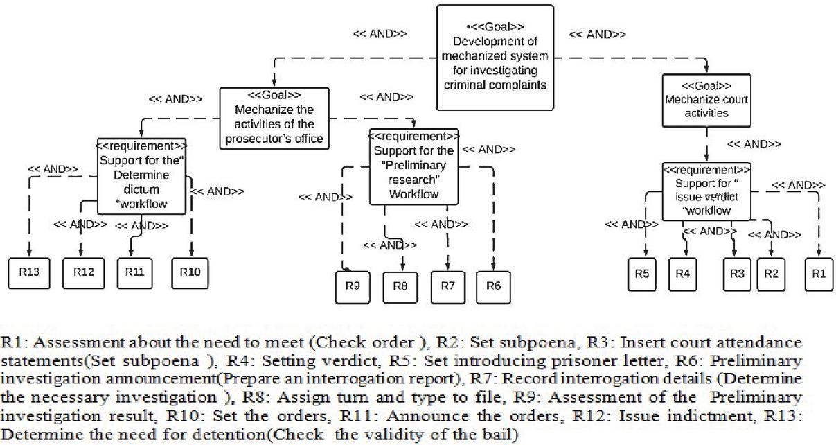
Figure 6 The To-Be model for “preliminary research process for a criminal case”.

Figure 7 The To-Be model for” issue verdict process for a criminal case.”.
5.3 Creating a Communication Matrix of Tasks and Requirements
This step aims to determine the relationships between the tasks and software requirements identified in the Section 5.1. So, the To-Be business process model will be examined to identify the tasks that address each of the requirements that exist in the last level of the requirements model. Then, as Table 2 describes, we construct a two-dimensional array that exhibits the relationship between each requirement and the task that relates to it:
| (1) |
Considering these relations, if organizations have the same goals, the tasks that address these goals can be reusable. So identified services with this attitude meet the reusability factor which is one of the service design principles. We use this matrix in Section 5.9 for identifying candidate services.
Table 2 Relationship between business process tasks and system requirements
| System Requirements | Tasks |
| Check order | t21 |
| Set subpoena | t22–t23–t24 |
| Insert court attendance statements set minutes | t26–t27–t28–t29 |
| Setting verdict | t30 |
| Set introducing prisoner letter | t31 |
| Prepare an interrogation report | t8–t9–t10 |
| Determine the necessary investigation | t5 |
| Assign turn and type to file | t2–t3 |
| Assesment of the preliminary investigation result | t6–t7 |
| Set the orders | t13–t14–t15 |
| Announce the orders | t20 |
| Issue indictment | t19 |
| Determine the need for detention (Check the validity of the bail) | t16–t17 |
| Check the preliminary investigation result | t11–t12 |
5.4 Creating the First Communication Tasks Matrix
Considering that software entities are an effective factor in identifying services, we need to create a task-entity matrix before creating the first communication task matrix.
The task-entity matrix is formed with two goals. First, using this matrix, the relationship between tasks and entities is determined, and secondly, the effect of tasks on each entity is identified. The effect of tasks on entities is categorized into four types of operations: create (C), update (U), read (R) and delete (D). This set of operations is known as CRUD and has a different degree of importance which is compared in [8] like CUDR. Accordingly, create (C) has the highest strength and importance degree in comparison with others. To use these four operations in different calculations, in [8], they have been assigned a numeric value. Assuming these numbers are real and are between 0 and 1. For simplicity of calculation, they rounded and set as follows. create (c) 1, Update (U) 0.75, Delete (d) 0.5 and read 0.25. By adopting these concepts from [8], we continued our method. We need to explore the relationships between tasks and entities. To accomplish each task a number of entities should be accessed to Create, Read, Update or Delete data. The Task-entity matrix rows are tasks and the columns are entities.
The value of each cell in the matrix is determined by the type of operation that each task performs on each entity. Should the operation be “create” the cell’s value will be equal to C or 1. Likewise, U or 0.75 for update, D or 0.5 for delete and R or 0.25 for read [8].
The Judicial System’s entities are determined in Table 3. Also, the task entity matrixes for the prosecutor’s office and court are shown in Tables 4 and 5.
Table 3 Judicial System’s entities
| E1 | Complaint |
| E2 | Required interrogation inquiry |
| E3 | Prosecutor’s office’s interrogation report |
| E4 | Conscious office’s final investigation report |
| E5 | Sheriff’s final investigation report |
| E6 | Decree for suspension of prosecution |
| E7 | Decree for finish prosecution |
| E8 | Guilty verdict |
| E9 | Decree for temporary detention |
| E10 | Order for bail document detention |
| E11 | Indictment |
| E12 | Defendant’s subpoena |
| E13 | Witness’s subpoena |
| E14 | Complainant’s subpoena |
| E15 | Court Minutes |
| E16 | Verdict |
| E17 | Introducing prisoner letter |
Table 4 Task entities matrix for prosecutor’s office
| E1 | E2 | E3 | E4 | E5 | E6 | E7 | E8 | E9 | E10 | E11 | |
| t1 | U | ||||||||||
| t2 | U | ||||||||||
| t3 | U | ||||||||||
| t4 | C | ||||||||||
| t5 | R | ||||||||||
| t6 | U | ||||||||||
| t7 | U | ||||||||||
| t8 | C | ||||||||||
| t9 | C | ||||||||||
| t10 | C | ||||||||||
| t11 | U | U | |||||||||
| t12 | U | ||||||||||
| t13 | R | R | R | C | |||||||
| t14 | R | R | R | C | |||||||
| t15 | R | R | R | C | |||||||
| t16 | R | C | |||||||||
| t17 | R | C | |||||||||
| t18 | U | U | U | ||||||||
| t19 | R | C | |||||||||
| t20 | R | R | R |
Table 5 Task entity matrix for court
| E6 | E7 | E11 | E12 | E13 | E14 | E15 | E16 | E17 | |
| t21 | R | R | R | ||||||
| t22 | C | ||||||||
| t23 | C | ||||||||
| t24 | C | ||||||||
| t25 | C | ||||||||
| t26 | U | ||||||||
| t27 | U | ||||||||
| t28 | U | ||||||||
| t29 | U | ||||||||
| t30 | C | ||||||||
| t31 | R | C |
We use the task-entity matrix to create the first communication task matrix. This matrix illustrates the relations between tasks based on their access to entities. Thus, it helps to determine semantic relations between tasks.
In the first step, for each two tasks in the business process model, if the two tasks are operating on one or a number of similar entities, the average of accessing types of the two tasks to each common entity will be calculated. The sum of these values will then be calculated. In the next step, the number of shared entities by these tasks will be divided by the total number of the entities that are accessed by these tasks. The result will be multiplied by the value calculated in the previous step. Finally, the result will be placed in the cell that is at the intersection of the two tasks in the matrix.
Algorithm 1 Creating the first communication task matrix
Applying this algorithm has two advantages. First, it helps us understand the relationship rate between tasks with respect to their impact on shared entities. Second, it allows us to extract the hidden and semantic relations between tasks. For example, by applying the above algorithm task 1 and task 3 are conceptually related to each other because both impact the same data. As we see in Tables 6 and 7, the rate of relation between tasks varies between 0,1. Identifying such relations lead to the identification of tasks that can be potentially considered as services. The first communication task matrixes for the prosecutor’s office and court are described in Tables 6 and 7.
Table 6 First communication task matrix for prosecutor’s office
| t1 | t2 | t3 | t4 | t5 | t6 | t7 | t8 | t9 | t10 | t11 | t12 | t13 | t14 | t15 | t16 | t17 | t18 | t19 | t20 | |
| t1 | 0 | 0.75 | 0.75 | 0 | 0 | 0 | 0 | 0 | 0 | 0 | 0 | 0 | 0 | 0 | 0 | 0 | 0 | 0 | 0 | 0 |
| t2 | 0.75 | 0 | 0.75 | 0 | 0 | 0 | 0 | 0 | 0 | 0 | 0 | 0 | 0 | 0 | 0 | 0 | 0 | 0 | 0 | 0 |
| t3 | 0.75 | 0.75 | 0 | 0 | 0 | 0 | 0 | 0 | 0 | 0 | 0 | 0 | 0 | 0 | 0 | 0 | 0 | 0 | 0 | 0 |
| t4 | 0 | 0 | 0 | 0 | 0.625 | 0 | 0 | 0 | 0 | 0 | 0 | 0 | 0 | 0 | 0 | 0 | 0 | 0 | 0 | 0 |
| t5 | 0 | 0 | 0 | 0.625 | 0 | 0 | 0 | 0 | 0 | 0 | 0 | 0 | 0 | 0 | 0 | 0 | 0 | 0 | 0 | 0 |
| t6 | 0 | 0 | 0 | 0 | 0 | 0 | 0 | 0 | 0 | 0 | 0.375 | 0 | 0.125 | 0.125 | 0.125 | 0 | 0 | 0 | 0 | 0 |
| t7 | 0 | 0 | 0 | 0 | 0 | 0 | 0 | 0 | 0 | 0 | 0.375 | 0 | 0.125 | 0.125 | 0.125 | 0 | 0 | 0 | 0 | 0 |
| t8 | 0 | 0 | 0 | 0 | 0 | 0 | 0 | 0 | 0 | 0 | 0 | 0.875 | 0.156 | 0.156 | 0.156 | 0 | 0 | 0 | 0 | 0 |
| t9 | 0 | 0 | 0 | 0 | 0 | 0 | 0 | 0 | 0 | 0 | 0 | 0.875 | 0.156 | 0.156 | 0.156 | 0 | 0 | 0 | 0 | 0 |
| t10 | 0 | 0 | 0 | 0 | 0 | 0 | 0 | 0 | 0 | 0 | 0 | 0.875 | 0.156 | 0.156 | 0.156 | 0 | 0 | 0 | 0 | 0 |
| t11 | 0 | 0 | 0 | 0 | 0 | 0.375 | 0 | 0 | 0 | 0 | 0 | 0 | 0.5 | 0.5 | 0.5 | 0 | 0 | 0 | 0 | 0 |
| t12 | 0 | 0 | 0 | 0 | 0 | 0 | 0 | 0.875 | 0.875 | 0.875 | 0 | 0 | 0.125 | 0.125 | 0.125 | 0 | 0 | 0 | 0 | 0 |
| t13 | 0 | 0 | 0 | 0 | 0 | 0.125 | 0.125 | 0.156 | 0.156 | 0.156 | 0.5 | 0.125 | 0 | 0.05 | 0.05 | 0 | 0 | 0 | 0 | 0.104 |
| t14 | 0 | 0 | 0 | 0 | 0 | 0.125 | 0.125 | 0.156 | 0.156 | 0.156 | 0.5 | 0.125 | 0.05 | 0 | 0.05 | 0 | 0 | 0 | 0 | 0.104 |
| t15 | 0 | 0 | 0 | 0 | 0 | 0.125 | 0.125 | 0.156 | 0.156 | 0.156 | 0.5 | 0.125 | 0.05 | 0.05 | 0 | 0.125 | 0.125 | 0.145 | 0.125 | 0 |
| t16 | 0 | 0 | 0 | 0 | 0 | 0 | 0 | 0 | 0 | 0 | 0 | 0 | 0 | 0 | 0.125 | 0 | 0.083 | 0.125 | 0.083 | 0 |
| t17 | 0 | 0 | 0 | 0 | 0 | 0 | 0 | 0 | 0 | 0 | 0 | 0 | 0 | 0 | 0.125 | 0.083 | 0 | 0.125 | 0.083 | 0 |
| t18 | 0 | 0 | 0 | 0 | 0 | 0 | 0 | 0 | 0 | 0 | 0 | 0 | 0 | 0 | 0.145 | 0.125 | 0.125 | 0 | 0.125 | 0.5 |
| t19 | 0 | 0 | 0 | 0 | 0 | 0 | 0 | 0 | 0 | 0 | 0 | 0 | 0 | 0 | 0.125 | 0.083 | 0.083 | 0.125 | 0 | 0.156 |
| t20 | 0 | 0 | 0 | 0 | 0 | 0 | 0 | 0 | 0 | 0 | 0 | 0 | 0.104 | 0.104 | 0 | 0 | 0 | 0.5 | 0.156 | 0 |
Table 7 First communication task matrix for court
| t21 | t22 | t23 | t24 | t25 | t26 | t27 | t28 | t29 | t30 | t31 | |
| t21 | 0 | 0 | 0 | 0 | 0 | 0 | 0 | 0 | 0 | 0 | 0 |
| t22 | 0 | 0 | 0 | 0 | 0 | 0 | 0 | 0 | 0 | 0 | 0 |
| t23 | 0 | 0 | 0 | 0 | 0 | 0 | 0 | 0 | 0 | 0 | 0 |
| t24 | 0 | 0 | 0 | 0 | 0 | 0 | 0 | 0 | 0 | 0 | 0 |
| t25 | 0 | 0 | 0 | 0 | 0 | 0.875 | 0.875 | 0.875 | 0.875 | 0 | 0 |
| t26 | 0 | 0 | 0 | 0 | 0.875 | 0 | 0.75 | 0.75 | 0.75 | 0 | 0 |
| t27 | 0 | 0 | 0 | 0 | 0.875 | 0.75 | 0 | 0.75 | 0.75 | 0 | 0 |
| t28 | 0 | 0 | 0 | 0 | 0.875 | 0.75 | 0.75 | 0 | 0.75 | 0 | 0 |
| t29 | 0 | 0 | 0 | 0 | 0.875 | 0.75 | 0.75 | 0.75 | 0 | 0 | 0 |
| t30 | 0 | 0 | 0 | 0 | 0 | 0 | 0 | 0 | 0 | 0 | 0.312 |
| t31 | 0 | 0 | 0 | 0 | 0 | 0 | 0 | 0 | 0 | 0.312 | 0 |
5.5 Creating Entity Services
In our method, the service model includes three types of services: entity service, utility service, and task service. Entity services are derived from the business data model. We identify each entity in the business data model as a service. Each service entails some methods. To determine these methods for each entity service, we look for the CRUD operations presented in the column associated with that entity in the task-entity matrix. The process is shown below.
| (2) |
Since entity services are derived from a business data model and are not dependent on a particular business process, they can be reused to automate different business processes. The identified Entity services for investigating criminal complaint mechanized system is shown in Table 8.
Table 8 Considered Entity services for investigating criminal complaint mechanized system
| Methods | Entity Service |
| Update() | Complaint |
| Create(), Read() | required interrogation inquiry |
| Create(),Update(),Read() | prosecutor’s office’ s interrogation report |
| Update(),Read() | conscious office’s final investigation report |
| Update(),Read() | sheriff’s final investigation report |
| Create(),Update(),Read() | decree for suspension of prosecution |
| Create(),Update(),Read() | decree for finish prosecution |
| Create(),Update(),Read() | Guilty verdict |
| Create() | decree for temporary detention |
| Create() | Order for bail document detention |
| Create(),Read() | Indictment |
| Create() | defendant’s subpoena |
| Create() | witness’s subpoena |
| Create() | complainant’s subpoena |
| Create(),Update() | Court Minutes |
| Create(),Read() | Verdict |
| Create() | Introducing prisoner letter |
5.6 Creating Utility Services
Utility services are designed to automate functions that are commonly used in various contexts and thus are independent of any particular business process and organization. These services, therefore, are reusable. For example, Log services on messages moving within the service-oriented architecture framework, error management service, and transaction monitoring service are recognized as utility services.
Also, the repetitive patterns of tasks in BPMN can be considered as utility services. Once identified, we add these services to the services model. Furthermore, in the description phase, we will show the relation between these services and other types of services.
5.7 Create a Second Communication Tasks Matrix
In this step, a second communication tasks matrix is generated from the To-Be business process model. We construct this matrix to illuminate the structural relations between tasks in the business process model. These relations will be used to identify task services in the next step. Tables 9 and 10 present the second communication tasks matrixes for the prosecutor’s office and court.
A number of analysis and design tools such as Visual Paradigm, can automatically generate this matrix using the BPMN model, but the matrix created by such tools has some shortcomings. For example, it only considers direct relation between two tasks and if a gate or event exists between them, they will not be taken into account as related tasks. Additionally, this tool neglects some series of patterns in business processes, such as tasks that are placed before or after a gateway that can be considered as services. To tackle these problems, we develop the following algorithm. To this end, we need to first determine edges, gateways, and branches. To do so, we create a new XML browsing tool that analyzes the XML version of BPMN.
Table 9 Second communication tasks matrix for prosecutor’s office
| t1 | t2 | t3 | t4 | t5 | t6 | t7 | t8 | t9 | t10 | t11 | t12 | t13 | t14 | t15 | t16 | t17 | t18 | t19 | t20 | |
| t1 | 0 | 1 | 0 | 0 | 0 | 0 | 0 | 0 | 0 | 0 | 0 | 0 | 0 | 0 | 0 | 0 | 0 | 0 | 0 | 0 |
| t2 | 0 | 0 | 1 | 0 | 0 | 0 | 0 | 0 | 0 | 0 | 0 | 0 | 0 | 0 | 0 | 0 | 0 | 0 | 0 | 0 |
| t3 | 0 | 0 | 0 | 0.25 | 0 | 0 | 0 | 0.25 | 0.25 | 0.25 | 0 | 0 | 0 | 0 | 0 | 0 | 0 | 0 | 0 | 0 |
| t4 | 0 | 0 | 0 | 0 | 1 | 0 | 0 | 0 | 0 | 0 | 0 | 0 | 0 | 0 | 0 | 0 | 0 | 0 | 0 | 0 |
| t5 | 0 | 0 | 0 | 0 | 0 | 0.5 | 0.5 | 0 | 0 | 0 | 0 | 0 | 0 | 0 | 0 | 0 | 0 | 0 | 0 | 0 |
| t6 | 0 | 0 | 0 | 0 | 0 | 0 | 0.75 | 0 | 0 | 0 | 0 | 0 | 0 | 0 | 0 | 0 | 0 | 0 | 0 | 0 |
| t7 | 0 | 0 | 0 | 0 | 0 | 0.75 | 0 | 0 | 0 | 0 | 0 | 0 | 0 | 0 | 0 | 0 | 0 | 0 | 0 | 0 |
| t8 | 0 | 0 | 0 | 0 | 0 | 0 | 0 | 0 | 0.75 | 0.75 | 0 | 0 | 0 | 0 | 0 | 0 | 0 | 0 | 0 | 0 |
| t9 | 0 | 0 | 0 | 0 | 0 | 0 | 0 | 0.75 | 0 | 0.75 | 0 | 0 | 0 | 0 | 0 | 0 | 0 | 0 | 0 | 0 |
| t10 | 0 | 0 | 0 | 0 | 0 | 0 | 0 | 0.75 | 0.75 | 0 | 0 | 0 | 0 | 0 | 0 | 0 | 0 | 0 | 0 | 0 |
| t11 | 0 | 0 | 0 | 0 | 0 | 0 | 0 | 0 | 0 | 0 | 0 | 0.75 | 0.5 | 0.5 | 0.5 | 0 | 0 | 0 | 0 | 0 |
| t12 | 0 | 0 | 0 | 0 | 0 | 0 | 0 | 0 | 0 | 0 | 0.75 | 0 | 0.5 | 0.5 | 0.5 | 0 | 0 | 0 | 0 | 0 |
| t13 | 0 | 0 | 0 | 0 | 0 | 0 | 0 | 0 | 0 | 0 | 0 | 0 | 0 | 0.75 | 0.75 | 0 | 0 | 0.5 | 0 | 0 |
| t14 | 0 | 0 | 0 | 0 | 0 | 0 | 0 | 0 | 0 | 0 | 0 | 0 | 0.75 | 0 | 0.75 | 0 | 0 | 0.5 | 0 | 0 |
| t15 | 0 | 0 | 0 | 0 | 0 | 0 | 0 | 0 | 0 | 0 | 0 | 0 | 0.75 | 0.75 | 0 | 0.5 | 0.5 | 0.5 | 0 | 0 |
| t16 | 0 | 0 | 0 | 0 | 0 | 0 | 0 | 0 | 0 | 0 | 0 | 0 | 0 | 0 | 0 | 0 | 0.75 | 0 | 0 | 0 |
| t17 | 0 | 0 | 0 | 0 | 0 | 0 | 0 | 0 | 0 | 0 | 0 | 0 | 0 | 0 | 0 | 0.75 | 0 | 0 | 0 | 0 |
| t18 | 0 | 0 | 0 | 0 | 0 | 0 | 0 | 0 | 0 | 0 | 0 | 0 | 0 | 0 | 0 | 0 | 0 | 0 | 0.5 | 0.5 |
| t19 | 0 | 0 | 0 | 0 | 0 | 0 | 0 | 0 | 0 | 0 | 0 | 0 | 0 | 0 | 0 | 0 | 0 | 0 | 0 | 0.75 |
| t20 | 0 | 0 | 0 | 0 | 0 | 0 | 0 | 0 | 0 | 0 | 0 | 0 | 0 | 0 | 0 | 0 | 0 | 0 | 0.75 | 0 |
Table 10 Second communication tasks matrix for court
| t21 | t22 | t23 | t24 | t25 | t26 | t27 | t28 | t29 | t30 | t31 | |
| t21 | 0 | 0.5 | 0.5 | 0.5 | 0 | 0 | 0 | 0 | 0 | 0.5 | 0 |
| t22 | 0.5 | 0 | 0 | 0 | 1 | 0 | 0 | 0 | 0 | 0 | 0 |
| t23 | 0.5 | 0 | 0 | 0 | 1 | 0 | 0 | 0 | 0 | 0 | 0 |
| t24 | 0.5 | 0 | 0 | 0 | 1 | 0 | 0 | 0 | 0 | 0 | 0 |
| t25 | 0 | 1 | 1 | 1 | 0 | 0.5 | 1 | 1 | 1 | 0 | 0 |
| t26 | 0 | 0 | 0 | 0 | 0.5 | 0 | 0 | 0 | 0 | 1 | 0 |
| t27 | 0 | 0 | 0 | 0 | 1 | 0 | 0 | 0 | 0 | 1 | 0 |
| t28 | 0 | 0 | 0 | 0 | 1 | 0 | 0 | 0 | 0 | 1 | 0 |
| t29 | 0 | 0 | 0 | 0 | 1 | 0 | 0 | 0 | 0 | 1 | 0 |
| t30 | 0.5 | 0 | 0 | 0 | 0 | 1 | 1 | 1 | 1 | 0 | 0.5 |
| t31 | 0 | 0 | 0 | 0 | 0 | 0 | 0 | 0 | 0 | 0.5 | 0 |
In our proposed algorithm, If the connection between the two tasks of Ti and Tj is direct in the business process model, the value of the cell (Ti, Tj) in the second task communication matrix will be equal to 1. Should there be a gateway between Ti and Tj, the value of 0.5 will be assigned. This value will be equal to 0.75 under the condition that Ti and Tj appear on branches that are positioned before or after a gateway.
Algorithm 2 Create the second communication task matrix
The output matrixes generated by the suggested algorithms facilitate the identification of both structural and semantic relations between tasks. For example, if task 1 and task 2 are related and also there is a relationship between task 2 and task 3, a potential relationship may exist between task 1 and task 3. This relationship and the associated tasks can be considered as a new service providing that they present the required features of service. Another example is a condition under which two tasks use the same data. These tasks may potentially be interdependent. Such relationships are of the semantic type that we identify in our method. So, the challenge of insufficient attention to the structural relationships between tasks in other service identification methods, is overcome by creating this matrix.
5.8 Creating a Final Communication Task Matrix
To identify task services and creating the final communication task matrix, we use the following equation. Accordingly, the final matrix is equal to the sum of the first and the second communication task matrices which shows relationship between tasks from both structural and conceptual points of view. For example, Figure 6 reveals that there is no explicit and structural relationship between task 1 and task 3, but by means of the first task-task communication matrix, we see that they have a conceptual relationship with each other. Therefore, the value of their related cell in the first and second communication matrix add together and is written in the corresponding cell in the final task-task matrix. This matrix for the prosecutor’s office and the court is depicted in Tables 11 and 12.
| (3) |
Table 11 Final communication task matrix for prosecutor’s office
| t1 | t2 | t3 | t4 | t5 | t6 | t7 | t8 | t9 | t10 | t11 | t12 | t13 | t14 | t15 | t16 | t17 | t18 | t19 | t20 | |
| t1 | 0 | 1.75 | 0.75 | 0 | 0 | 0 | 0 | 0 | 0 | 0 | 0 | 0 | 0 | 0 | 0 | 0 | 0 | 0 | 0 | 0 |
| t2 | 0.75 | 0 | 1.75 | 0 | 0 | 0 | 0 | 0 | 0 | 0 | 0 | 0 | 0 | 0 | 0 | 0 | 0 | 0 | 0 | 0 |
| t3 | 0.75 | 0.75 | 0 | 0.5 | 0 | 0 | 0 | 0.5 | 0.5 | 0.5 | 0 | 0 | 0 | 0 | 0 | 0 | 0 | 0 | 0 | 0 |
| t4 | 0 | 0 | 0 | 0 | 1.625 | 0 | 0 | 0 | 0 | 0 | 0 | 0 | 0 | 0 | 0 | 0 | 0 | 0 | 0 | 0 |
| t5 | 0 | 0 | 0 | 0.625 | 0 | 0.5 | 0.5 | 0 | 0 | 0 | 0 | 0 | 0 | 0 | 0 | 0 | 0 | 0 | 0 | 0 |
| t6 | 0 | 0 | 0 | 0 | 0 | 0 | 0.75 | 0 | 0 | 0 | 0.375 | 0 | 0.125 | 0.125 | 0.125 | 0 | 0 | 0 | 0 | 0 |
| t7 | 0 | 0 | 0 | 0 | 0 | 0.75 | 0 | 0 | 0 | 0 | 0.375 | 0 | 0.125 | 0.125 | 0.125 | 0 | 0 | 0 | 0 | 0 |
| t8 | 0 | 0 | 0 | 0 | 0 | 0 | 0 | 0 | 1.75 | 1.75 | 0 | 0.875 | 0.156 | 0.156 | 0.156 | 0 | 0 | 0 | 0 | 0 |
| t9 | 0 | 0 | 0 | 0 | 0 | 0 | 0 | 1.75 | 0 | 1.75 | 0 | 0.875 | 0.156 | 0.156 | 0.156 | 0 | 0 | 0 | 0 | 0 |
| t10 | 0 | 0 | 0 | 0 | 0 | 0 | 0 | 1.75 | 1.75 | 0 | 0 | 0.875 | 0.156 | 0.156 | 0.156 | 0 | 0 | 0 | 0 | 0 |
| t11 | 0 | 0 | 0 | 0 | 0 | 0.375 | 0 | 0 | 0 | 0 | 0 | 0.75 | 1 | 1 | 1 | 0 | 0 | 0 | 0 | 0 |
| t12 | 0 | 0 | 0 | 0 | 0 | 0 | 0 | 0.875 | 0.875 | 0.875 | 0.75 | 0 | 0.625 | 0.625 | 0.625 | 0 | 0 | 0 | 0 | 0 |
| t13 | 0 | 0 | 0 | 0 | 0 | 0.125 | 0.125 | 0.156 | 0.156 | 0.156 | 0.5 | 0.125 | 0 | 0.8 | 0.8 | 0 | 0 | 0.5 | 0 | 0.104 |
| t14 | 0 | 0 | 0 | 0 | 0 | 0.125 | 0.125 | 0.156 | 0.156 | 0.156 | 0.5 | 0.125 | 0.8 | 0 | 0.8 | 0 | 0 | 0.5 | 0 | 0.104 |
| t15 | 0 | 0 | 0 | 0 | 0 | 0.125 | 0.125 | 0.156 | 0.156 | 0.156 | 0.5 | 0.125 | 0.8 | 0.8 | 0 | 0.625 | 0.625 | 0.5 | 0.125 | 0 |
| t16 | 0 | 0 | 0 | 0 | 0 | 0 | 0 | 0 | 0 | 0 | 0 | 0 | 0 | 0 | 0.125 | 0 | 0.833 | 0.125 | 0.083 | 0 |
| t17 | 0 | 0 | 0 | 0 | 0 | 0 | 0 | 0 | 0 | 0 | 0 | 0 | 0 | 0 | 0.125 | 0.833 | 0 | 0.125 | 0.083 | 0 |
| t18 | 0 | 0 | 0 | 0 | 0 | 0 | 0 | 0 | 0 | 0 | 0 | 0 | 0 | 0 | 0.145 | 0.125 | 0.125 | 0 | 0.625 | 1 |
| t19 | 0 | 0 | 0 | 0 | 0 | 0 | 0 | 0 | 0 | 0 | 0 | 0 | 0 | 0 | 0.125 | 0.083 | 0.083 | 0.125 | 0 | 0.91 |
| t20 | 0 | 0 | 0 | 0 | 0 | 0 | 0 | 0 | 0 | 0 | 0 | 0 | 0.104 | 0.104 | 0 | 0 | 0 | 0.5 | 0.91 | 0 |
Table 12 Final communication task matrix for prosecutor’s office
| t21 | t22 | t23 | t24 | t25 | t26 | t27 | t28 | t29 | t30 | t31 | |
| t21 | 0 | 1 | 1 | 1 | 0.5 | 0.5 | 0.5 | 0.5 | 0.5 | 1 | 0.5 |
| t22 | 1 | 0 | 2 | 2 | 2 | 1 | 1 | 1 | 1 | 1 | 1 |
| t23 | 1 | 2 | 0 | 2 | 2 | 1 | 1 | 1 | 1 | 1 | 1 |
| t24 | 1 | 2 | 2 | 0 | 2 | 1 | 1 | 1 | 1 | 1 | 1 |
| t25 | 0.5 | 2 | 2 | 2 | 0 | 2.5 | 3 | 3 | 3 | 1 | 1 |
| t26 | 0.5 | 1 | 1 | 1 | 2.5 | 0 | 2 | 2 | 2 | 2 | 1 |
| t27 | 0.5 | 1 | 1 | 1 | 3 | 2 | 0 | 2 | 2 | 2 | 1 |
| t28 | 0.5 | 1 | 1 | 1 | 3 | 2 | 2 | 0 | 2 | 2 | 1 |
| t29 | 0.5 | 1 | 1 | 1 | 3 | 2 | 2 | 2 | 0 | 2 | 1 |
| t30 | 1 | 1 | 1 | 1 | 1 | 2 | 2 | 2 | 2 | 0 | 1.5 |
| t31 | 0.5 | 1 | 1 | 1 | 1 | 1 | 1 | 1 | 1 | 1.5 | 0 |
5.9 Creating Candidate task Services
In this step, we create a service for each system requirement, which is defined at the final level of the goal model. Creating services with respect to the requirements of organizations makes the service-oriented system more flexible. When a business needs changes, only the service related to that change will be altered, leaving the rest of the services untouched. Then, by using the following algorithm, we identify the methods that are associated with the service we defined. This algorithm operates in two sequential phases. In the first phase, it reviews the requirement-task matrix which had been developed in 5.3. From this matrix, the algorithm identifies the tasks that address each business need. It, then, categorizes these tasks as methods related to services. The algorithm may come across some tasks that have been previously assigned to another service. Under a circumstance as such, those tasks will remain as a subset of the service that they had been initially assigned to. However, they will be called in when their functions are needed to complete the new service. When this happens, the previous service will become preempt.
In the next phase, the algorithm looks for the remaining methods for each service. To do this, from the final communication tasks matrix, it extracts and adds those tasks that are related to the methods of each service and do not belong to any other recognized services. Although this set of tasks may not be directly in alignment with any specific business requirement, they are semantically related to the other methods identified for a particular service.
This semantic relationship can be of two types: implicit control flow and data flow. These relationships are prerequisites for the execution of the identified service methods. Then, each task that remains unassigned to any service will be allocated to a new service. Finally, the algorithm elucidates the relationships between the identified task services and other types of services such as entity and utility services. The candidate services for our example are shown in Table 13.
Algorithm 3 Requirement-based service identification
Table 13 Candidate services for judicial system
| Service | Methods | |
| S1 | Create file | t1–t2–t3 |
| S2 | Determine the necessary investigation | t4–t5 |
| S3 | Assessment of the preliminary investigation result | t6–t7 |
| S4 | Prepare an interrogation report | t8–t9–t10 |
| S5 | Check the preliminary investigation result | t11–t12 |
| S6 | Set orders | t13–t14–t15 |
| S7 | Check the validity of the bail | t16–t17 |
| S8 | Assessment about the orders | t18–t20 |
| S9 | Issue indictment | t19 |
| S10 | Check order | t21 |
| S11 | Set subpoena | t22–t23–t24 |
| S12 | Set minutes | t25–t26–t27–t28–t29 |
| S13 | Issue verdict | t30 |
| S14 | Set introducing prisoner letter | t31 |
5.10 Creating the Dependency Service Matrix
In this step, the internal cohesion degree of the identified services’ methods and the connection between them is calculated and displayed in the related service matrix. This matrix will be used to improve the candidate services in the next step. The rows and columns of this matrix are the services. The main diagonal of the matrix indicates the cohesion of methods within each service.
To calculate the cohesion of a service’s methods, if the service has one method, the value of its cohesion is equal to one. If the number of service methods is greater than one, the cohesion value is calculated by the formula presented below. The values of the variables in the formula are derived from the final task-communication matrix.
| (4) |
Also, the coupling degree between the two services is calculated from the following formula.
The Dependency Service Matrixes related to the preliminary research process and issue verdict process for a criminal case in the prosecutor’s office is depicted in Tables 14 and 15.
Table 14 Dependency Service Matrix related to the preliminary research process for a criminal case” in prosecutor’s office
| S1 | S2 | S3 | S4 | |
| S1 | 6.5 | 0.5 | 0 | 1.5 |
| S2 | 1 | 2.25 | 1 | 0 |
| S3 | 0 | 0 | 1.5 | 0 |
| S4 | 0 | 0 | 0 | 10.5 |
Table 15 Dependency Service Matrix related to verdict process for a criminal case in prosecutor’s office
| S5 | S6 | S7 | S8 | S9 | |
| S5 | 1.5 | 4.875 | 0 | 0 | 0 |
| S6 | 1.875 | 4.8 | 1.25 | 1.71 | 0.125 |
| S7 | 0 | 0.25 | 1.66 | 0.25 | 1.61 |
| S8 | 0 | 0.35 | 0.25 | 1.5 | 1.53 |
| S9 | 0 | 0.125 | 0.17 | 1.03 | 1 |
5.11 Revising Candidate Services
In this step, we create a variable that measures the ratio of the average cohesion of methods in each service to the average coupling degree of all services. This ratio indicates the quality of service design.
| (6) |
To calculate the average cohesion of identified services, the total cohesion of all services is calculated and divided by the total number of services. In this calculation, the dependency service matrix is used.
| (7) |
To calculate the average coupling of services in the services model, the following formula is used. In this formula, D represents the total number of connections between services. We find this value from the dependency matrix.
| (8) |
The following algorithm shows how to use the R variable to modify the services set:
Algorithm 4 Aggregate services
The final identified services for “investigating criminal complaint system: is described in Table 16.
Table 16 Final identified services for investigating criminal complaint system
| Service | Methods |
| Create file | t1–t2–t3 |
| Determine the necessary investigation | t4–t5 |
| Investigation of research results | t6–t7–t11 |
| Prepare an interrogation report | t8–t9–t10–t12 |
| Set order | t11–t12–t13–t14–t15 |
| Decision about detention | t16–t17 |
| Send orders | t18–t19–t20 |
| Check the order | t21 |
| Set subpoena | t22–t23–t24 |
| Set minutes | t25–t26–t27–t28–t29 |
| Issue verdict | t30–t31 |
6 Comparison of the Proposed Method With Existing Methods
In this section, we draw a comparison between the proposed method in this article and other methods that had been previously developed. Although numerous methods for identifying services have been introduced, we delimit the scope of this comparison to those papers that have suggested methods for developing model-driven service-oriented systems from BPMN. To do so, we provide comparative table that compares our method with other methods from different points of view. Table 17 shows the comparison between general service identification methods from various aspects. We then, empirically evaluate the utility of our method and compare it with other methods.
Table 17 The comparison of general service identification methods
The information presented in the table reflects the claims and arguments of the developers of the methods. For example, although [8, 12] and [13] have argued that their methods are fully automated, a closer look at them reveals that they suggest some degree of human intervention and thus are considered as semi-automated methods.
For identifying services, the reviewed methods have employed different tactics of analyzing inputs, processes, goals, and data. Our method, however, incorporates all of these tactics to identify both structural and semantic relationships between tasks. While being semi-automated, our method has the advantage of considering the principles of service design such as internal cohesion of service methods, loose coupling of services and reusability.
To empirically evaluate our method, we ran two tests. First, we compared our method against other methods by calculating the ratio of cohesion to coupling. In this comparison, we illustrated the values of this ratio for our proposed method as well as for the business process-oriented, goal-oriented and data-oriented approaches. Second, we sought experts’ opinions on the accuracy of these methods. To do so, we asked three experts to compare the aforementioned methods by appraising the quality of these methods with regard to their capabilities of identifying the right set of services and the associated tasks. They were allowed to apply each approach they want in every single strategy. Then, They were asked to rate the methods on a scale of 1 to 10 with 10 being the highest and 1 the lowest scores. They were instructed to deduct one mark for each misaligning task with a service identified by each method. We then, calculated the average of the scores given by the experts. The results demonstrate that our proposed method scored higher than the other ones. The results are summarized in Table 18.
Table 18 Method evaluation by variable R and expert evaluation
| Method/Service | Business Processes | Goals | Entities | Proposed Method |
| Service1 | t1–t2–t3 | t1–t2–t3 | t1–t2–t3 | t1–t2–t3 |
| Service2 | t4–t5 | t4–t5 | t4–t5 | t4–t5 |
| Service3 | t6–t7 | t6–t7–t11 | t6–t7–t11 | t6–t7–t11 |
| Service4 | t8–t9–t10 | t8–t9–t10–t11 | t8–t9–t10–t12 | t8–t9–t10–t12 |
| Service5 | t13–t14–t15 | t13–t14–t15–t16 | t13–t14–t15–t18–t19–t20 | t13–t14–t15 |
| Service6 | t16–t17 | t17 | t16–t17 | t16–t17 |
| Service7 | t18–t19–t20 | t18–t19–t20–t21 | – | t18–t19–t20–t21 |
| Service8 | t21–t22–t23–t24 | t21 | t21 | t21 |
| Service9 | – | t22–t23–t24 | t22–t23–t24 | t22–t23–t24 |
| Service10 | t25–t26–t27–t28–t29 | t25–t26–t27–t28–t29 | t25–t26–t27–t28–t29 | t25–t26–t27–t28–t29 |
| Service11 | t30–t31 | t30 | t30–t31 | t30–t31 |
| Service12 | t11–t12 | t31 | – | – |
| R variable | 2.435 | 1.195 | 1.874 | 2.511 |
| Experts evaluation | 8 | 6 | 8 | 10 |
The result of Table 18 shows that considering goal, data, and business views together leads to identifying services with a higher rate of cohesion and a looser rate of coupling between tasks compared to using each method alone. It means that applying combination view has helped to identifying more accurate services with more less call between them.
For another quantity evaluation, we compare the accuracy of our combination method with other single methods. Here accuracy means the number of tasks that are identified correctly as a method of each service. To do this, we consider several different processes with different degrees of complexity. Complexity means the number of tasks and gateway that exist in the process. Then, we asked the experts to identify services by applying different methods based on business-driven, goal-driven, entity-driven and by their choices separately. Then, we compared the average of their results with identified services that came from our method. Table 19 shows that our method identified services with higher accuracy in comparison with others. Also, results show that our method is independent from the size and complexity of the business process model and it works better than other methods in each situation.
Table 19 Comparison accuracy between approaches
| Method | Business Process | Goal | Entity | Proposed Method |
| Accuracy | 69.3 | 77.7 | 80.2 | 89.2 |
It is necessary to mention that the research domain of this paper consider goal, data and business view of service identification approaches together and presents a new combination method and shows the advantages in comparison to each single view. There are lots of other views with their combination approaches that don’t consider these three views. So, they are not in noted in this paper.
Comparison between our combination method with other combination method is opening the new topic for future research.
7 Conclusion
This article offers a new approach to semi-automated detection of services through the analysis of the direct and indirect relations amongst the tasks/activities in BPMN models. By definition, a service consists of an autonomous set of correlated reusable activities. We show that an autonomous set of activities/tasks which operate on the same entity or resource could be considered as a service. Moreover, having the same objective or goal may be used as another basis to consider a set of activities/tasks as a service. Highly cohesive and loosely coupled activities can also constitute a service. To do this, our approach is divided into two phases. First, in the business modeling phase we defined three models: goal, As-is and business data model. These models determined the requirements, current situation of a business, without considering any system or software, their tasks and the data flow. These models are used as input for the second phase: identification. In this phase, we identified services by specifying and measuring dependencies and relations between tasks in To-Be BPMN models with creating six matrices: task-requirement, task-entity, first communication task-task, second communication task-task, final communication task-task, and dependency service. These matrices measure and distinguish explicit and implicit both structural and semantic relationships between tasks and requirements, tasks and data, tasks together with attention to data flow between them to specify semantic relations, tasks together with considering structural relationship between them, task together with take into account to both structural and semantic relationships, and between identified services relations to measure dependency degree between them. Finding the dependencies shows the degree of control and data flows between tasks and help us to determine high cohesion and loose coupling tasks. At the end of this phase, we have three types of services: entity, utility, and task. The identification methods for each one are described in paper. The semi-automated method that introduced in this article has four features of high cohesion, loose coupling, granularity, and reusability. Simultaneously, it considers both structural and semantic relations. These features are gained by defining R index, paying attention to relation between tasks, system requirements and separate defining of entity and utility services to identify services. Other researchers should look into the possibility of automatically detecting services from BPMN models as well as extracting the BPMN from the system log.
References
[1] J. Dehnert, and W. M. Van Der Aalst, ‘Bridging the gap between business models and workflow specifications,’ International Journal of Cooperative Information Systems, vol. 13, no. 03, pp. 289–332, 2004
[2] A. Delgado, F. Ruiz, I. G.-R. de Guzmán, and M. Piattini, ‘Business process service-oriented methodology (BPSOM) with service generation in SoaML’ pp. 672–680.
[3] M. Stollberg, B. Elvesæter, V. Shafran, and R. Magarshak, ‘A Customizable Methodology for the Model-driven Engineering of Service-based System Landscapes’, paper presentation at MDA4ServiceCloud’10, Paris, France, 15 June 2010. http://events.sti2.at/mda4ServiceCloud2010/
[4] G. Qing, and P. Lago, ‘Service identification methods: A systematic literature review,’ Towards a Service-Based Internet, pp. 37–50, 2010.
[5] S. Cai, L. Yan, and W. Xiaoping. ‘A Survey of Service Identification Strategies.’ In Services Computing Conf. (APSCC), 2011 IEEE Asia-Pacific, pp. 464–470. IEEE, 2011.
[6] A. Anaby-Tavor, D. Amid, A. Sela, A. Fisher, K. Zhang, and O. T. Jun, ‘Towards a model driven service engineering process.’ In Services-Part I, 2008. IEEE Congress. pp. 503–510, 2008.
[7] A. Arsanjani, S. Ghosh, A. Allam, T. Abdollah, S. Ganapathy, and K. Holley, ‘SOMA: A method for developing service-oriented solutions,’ IBM systems Journal, vol. 47, no. 3, pp. 377–396, 2008.
[8] P. Jamshidi, S. Mansour, K. Sedighiani, S. Jamshidi, and F. Shams, An automated service identification method, Technical report, TR-ASER-2012-01, Automated Software Engineering Research …, 2012.
[9] A. Delgado, and L. González, ‘Automatic generation of SOAs for Business Process execution: A vision based on models.’, CLEI Conf .on Computing., pp. 1-10, IEEE, 2013.
[10] Y. Kim, and K.-G. Doh, ‘Formal identification of right-grained services for service-oriented modeling’, Int Conf. on Web Information Systems Engineering., pp. 261–273, Berlin, 2009.
[11] A. Delgado, F. Ruiz, I. G.-R. de Guzmán, and M. Piattini, ‘MINERVA: model driven and service oriented framework for the continuous business process improvement and related tools.’, ICSOC/Service Wave Workshops, pp. 456–466, Berlin Heidelberg, 2010.
[12] H. Jain, H. Zhao, and N. R. Chinta, ‘A spanning tree based approach to identifying web services,’ International Journal of Web Services Research (IJWSR), vol. 1, no. 1, pp. 1–20, 2004.
[13] A. Kazemi, A. Rostampour, P. Jamshidi, E. Nazemi, F. Shams, and A. N. Azizkandi, ‘A genetic algorithm based approach to service identification.’, 11 IEEE World Congress on Services, pp. 339–346, 2011.
[14] M. Weske, ‘Business process management architectures,’ Business Process Management: Concepts, Languages, Architectures, pp. 305–343, 2007.
[15] S. Mani, V. S. Sinha, N. Sukaviriya, and T. Ramachandra, ‘Using user interface design to enhance service identification.’, ICWS’08 Int.Conf. on Web Services, pp. 78–87, 2008.
[16] J.-w. Hubbers, A. Ligthart, and L. Terlouw, ‘Ten ways to identify services,’ The SOA Magazine, vol. 48, pp. 1–7 12, 2007.
[17] S. Chaari, F. Biennier, J. Favrel, and C. Benamar, ‘Towards a service-oriented enterprise based on business components identification,’ Enterprise Interoperability II, pp. 495–506, 2007.
[18] N. Fareghzadeh, ‘Service identification approach to SOA development’,Proc. In World Academy of Science, Engineering and Technology, vol. 35, pp. 258–266, 2008.
[19] R. S. Huergo, P. F. Pires, F. C. Delicato, B. Costa, E. Cavalcante, and T. Batista, ‘A systematic survey of service identification methods,’ Service Oriented Computing and Applications, vol. 8, no. 3, pp. 199–219, 2014.
[20] Q. Gu, and P. Lago, ‘Service identification methods: a systematic literature review.’,European Conf. on Towards a Service-Based Internet., pp. 37–50, Berlin, 2010.
[21] L. G. Azevedo, F. Santoro, F. Baião, J. Souza, K. Revoredo, V. Pereira, and I. Herlain, ‘A method for service identification from business process models in a SOA approach,’ Enterprise, Business-Process and Information Systems Modeling, pp. 99–112, 2009.
[22] L. G. Azevedo, F. Santoro, F. Baião, T. Diirr, A. Souza, J. F. de Souza, and H. P. Sousa, ‘A method for bridging the gap between business process models and services,’ iSys-Revista Brasileira de Sistemas de Informação, vol. 6, no. 1, pp. 62–98, 2014.
[23] I. Zafar, F. Azam, M. W. Anwar, B. Maqbool, W. H. Butt, and A. Nazir, ‘A Novel Framework to Automatically Generate Executable Web Services From BPMN Models,’ IEEE Access, vol. 7, pp. 93653–93677, 2019.
[24] I. Zafar, F. Azam, M. W. Anwar, W. H. Butt, B. Maqbool, and A. K. Nazir, ‘Business process models to Web services generation: A systematic literature review.’, IEEE, IEMCON. Conf . on Information Technology, Electronics and Mobile Communication, pp. 789–794, 2018.
[25] M. Abdellatif, et al., ‘State of the practice in service identification for soa migration in industry.’ Int. Conf. on Service-Oriented Computing. pp. 634–650, 2018.
[26] J. Touzi, F. Benaben, H. Pingaud, and J. P. Lorré, ‘A model-driven approach for collaborative service-oriented architecture design,’ International journal of production economics, vol. 121, no. 1, pp. 5–20, 2009.
[27] D. Bianchini, C. Cappiello, V. De Antonellis, and B. Pernici, ‘Service identification in interorganizational process design,’ IEEE Transactions on Services Computing, vol. 7, no. 2, pp. 265–278, 2013.
[28] A. Van Lamsweerde, ‘Goal-oriented requirements engineering: A guided tour’, Proc. In 5th IEEE Int. Sym. on Requirements Engineering pp. 249–262, Aug.,2001.
[29] F. Vares, M. J. Amiri, and S. Parsa, ‘Towards a model-driven development of enterprise systems’, IEEE (CSSE) Int. Conf. on Computer Science and Software Engineering., pp. 42–48, Oct., 2017.
[30] A. I. Anton, ‘Goal-based requirements analysis’, Proc. 2 th IEEE Int. Conf. on Requirements Engineering., pp. 136–144, 1996.
[31] V. N. T. V. T. Asakura, and T. V. Takeo, ‘Use of business modeling in requirements definition phase,’ Fujitsu Sci. Tech. J, vol. 42, no. 3, pp. 316–322, 2006.
[32] M. J. Amiri, S. Parsa, and A. M. Lajevardi, ‘Multifaceted service identification: process, requirement and data,’ Computer Science and Information Systems, vol. 13, no. 2, pp. 335–358, 2016.
[33] H. A. Reijers, and S. L. Mansar, ‘Best practices in business process redesign: an overview and qualitative evaluation of successful redesign heuristics,’ Omega, vol. 33, no. 4, pp. 283–306, 2005.
[34] S. Kim, M. Kim, and S. Park, ‘Service identification using goal and scenario in service oriented architecture’, 15th APSE IEEE Conf. on Software Engineering, pp. 419–426, 2008.
[35] S. Inaganti, and G. K. Behara, ‘Service identification: BPM and SOA handshake,’ BPTrends, vol. 3, pp. 1–12, 2007.
[36] P. Jamshidi, M. Sharifi, and S. Mansour, ‘To establish enterprise service model from enterprise business model’, SCC’08 IEEE Int. Conf. on Service Computing., vol. 1, pp. 93–100, 2008.
[37] S. H. Chang, and S. D. Kim, ‘A service-oriented analysis and design approach to developing adaptable services’, SCC’07 IEEE Int. Conf. on Service Computing, pp. 204–211, 2007.
[38] K. Levi, and A. Arsanjani, ‘A goal-driven approach to enterprise component identification and specification,’ Communications of the ACM, vol. 45, no. 10, pp. 45–52, 2002.
[39] S. Stein, S. Kühne, and K. Ivanov, ‘Business to it transformations revisited’, Business Process Management Workshops, pp. 176–187, Berlin Heidelberg, 2009.
[40] M. Leotta, G. Reggio, F. Ricca, and E. Astesiano, ‘Towards a lightweight model driven method for developing SOA systems using existing assets’, WSE 14th IEEE Int. Symp. on Web Systems Evolution, pp. 51–60, 2012.
[41] A. Delgado, F. Ruiz, I. G.-R. de Guzmán, and M. Piattini, ‘Model transformations for Business-IT alignment: from collaborative business process to SoaML service model’, Proc. 27th ACM Symp. on Applied Computing., pp. 1720–1722, 2012.
[42] A. Erradi, S. Anand, and N. Kulkarni, ‘SOAF: An architectural framework for service definition and realization’, SCC’06 IEEE Int. Conf. on Service Computing., pp. 151–158, 2006.
[43] P. Weiss, ‘Modeling of Service-Oriented Architecture: Integration of Business Process and Service Modeling,’ Information Sciences and Technologies Bulletin, pp. 79–92, 2010.
[44] M. Gebhart, and J. Bouras, ‘Derivation of web service implementation artifacts from service designs based on soaml,’ International Journal on Advances in Software, vol. 6, no. 1, pp. 170–180, 2013.
[45] C. Dumez, J. Gaber, and M. Wack, ‘Modeling and specification of web services composition using uml-s’, 4th Int. Conf. on Next Generation Web Services Practices, pp. 15–20, 2008.
[46] M. López-Sanz, C. J. Acuña, C. E. Cuesta, and E. Marcos, ‘Modelling of service-oriented architectures with UML,’ Electronic Notes in Theoretical Computer Science, vol. 194, no. 4, pp. 23–37, 2008.
[47] M. Marbouti, and F. Shams, ‘An Automated Service Realization Method’, Vol. 9, no. 2, pp. 188–195, 2012.
Biographies

Shahrzad Hekmat received her BS degree from Azad University, Iran, and her MS degree from Tehran University, in 2009 and 2011, respectively, both in Computer Engineering. She is currently studying her PhD in the Department of Computer Engineering, Azad University Central Tehran Branch. Her research interests are in the areas of software engineering, service oriented systems and process mining.

Saeed Parsa received his BSc in mathematics and computer science from Sharif University of Technology, Iran, his MS degree in computer science from the University of Salford in England, and his PhD in computer science from the University of Salford, England. He is an associate professor of computer science at Iran University of Science and Technology. His research interests include software engineering, soft computing and algorithms.

Babak Vaziri received his B.S. degree in computer engineering from Shahid Beheshti University, Iran, his M.S., and a Ph.D. degree in computer engineering from Islamic Azad University, Iran. He is currently an Assistant Professor of Computer Engineering in the Department of Computer Engineering, Central Tehran Branch, Islamic Azad University, Tehran, Iran. His research interests include software and process re-engineering and data mining.
Journal of Web Engineering, Vol. 21_3, 569–608.
doi: 10.13052/jwe1540-9589.2131
© 2022 River Publishers