Image Link Through Adaptive Encoding Data Base and Optimized GPU Algorithm for Real-time Image Processing of Artificial Intelligence
Byoungman An and Youngseop Kim*
Electronic and Electrical Engineering, Dankook University, 152, Jukjeon-ro, Suji-gu, Yongin-si, Gyeonggi-do, 16890, Korea
E-mail: yesbman@naver.com; wangcho@dankook.ac.kr
*Corresponding Author
Received 04 June 2021; Accepted 04 November 2021; Publication 07 January 2022
Abstract
This paper presents the latest Ethernet standardization of in-vehicle network and the future trends of automotive ethernet technology. The proposed system provides a design and optimization algorithm of in-vehicle networking technologies related Ethernet Audio Video Bridge (AVB) technology. We present a design of in-vehicle network system as well as the optimization of AVB for automotive. A proposal of Reduced Latency of Machin to Machine (RLMM) plays a significant role in reducing the latency between devices. The approach of RLMM on realistic test cases indicated that there was a latency reduction about 30.41% It is expected that the optimized settings for the actual automotive network environment can greatly shorten the time period in the development and design process. The results achieved from the experiments on the latency present in each function are trustworthy since average values are obtained via repeated tests for several months. It would considerably benefit the industry because analyzing the delay between each function in a short period of time is tremendously significant. In addition, through the proposed real-time camera and video streaming via optimized settings of AVB system, it is expected that AI (Artificial Intelligence) algorithms in autonomous driving will be of great help in understanding and analyzing images in real time.
Keywords: Image link, in-vehicle, GPU algorithm optimization, audio video bridge, AVB, low latency, automotive, multimedia, artificial intelligence, data base.
1 Introduction
Automotive application has many differences in the use-cases and technical requirements as compared with various types of application; thus, the new audio/video transmission technologies as Ethernet Audio Video Bridge (eAVB) are emerged [1]. This presentation starts with the background for the technological introduction into automotive network based on the features of Ethernet and in vehicle requirements. The time sensitive video and audio data streams in an automotive bridged local area network (LAN) requires the selection of specific features that are specified in a number of various standard because the media is increasingly transported in automotive environment. Streaming audio/video over the network to interactive applications requires real-time performance similar to legacy analog capabilities. Vendors and users significantly interest in defining a common method for handling real time audio/video. The simple audio/video transport over multiple IEEE (Institute of Electrical and Electronics Engineers) 802 network types will achieve operational benefits. IEEE Ethernet AVB (Audio Video Bridge) technology and standards provide transport mechanisms for time sensitive audio/video streams, it lessens the effort of producing inter working units among various networks [2]. In this paper, we suggest an up-to-date overview of it as well as describes the basic of the key element of eAVB; in addition, the paper gives why eAVB is an excellent candidate for next generation automotive infrastructures.
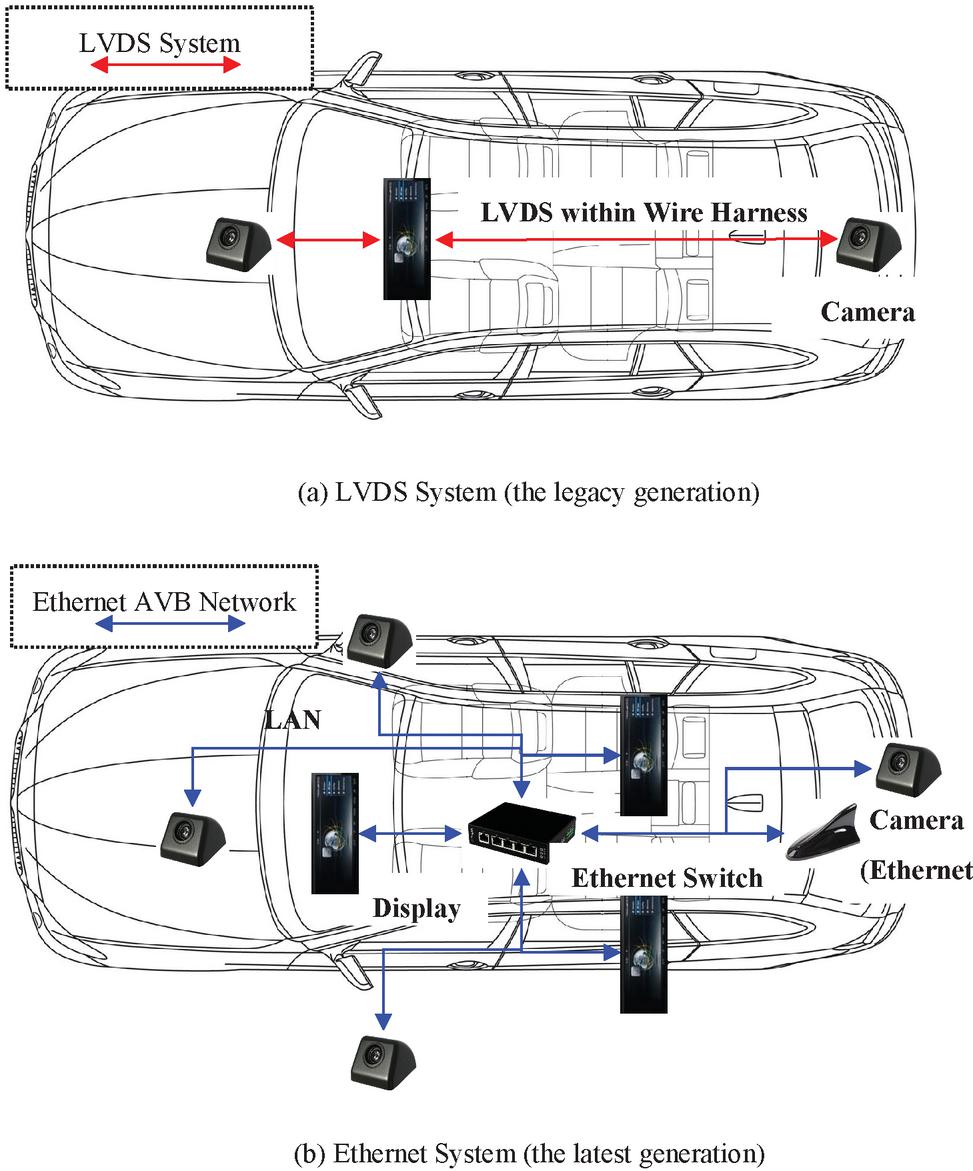
Figure 1 A difference between the legacy in-vehicle system (a) and the latest in-vehicle system (b).
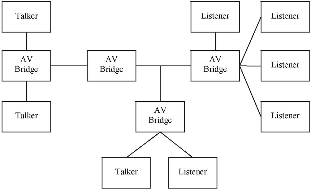
Figure 2 An example high level AVB Network.
A plenty of technology has been aimed to research the low latency of distributed real time network in vehicle [3]. Several study studies present various deployment and test configurations from simple networks with two end nodes and one switch to more duplicated in-vehicle networks with multiple endpoints and a multitude of switches between them. To interconnect systems, there is a need for larger bandwidth with determinism and flexibility. Also, many subsystems are safety critical because automotive industry has to deal with is a lot of existing networking algorithms. Considering the vehicle’s safety, it is influential to move from using numerous technologies to use the general standard. To increase safety as well as minimize the complexity, it is profitable to commit on a set of automotive networking technologies that can be adopted in most of the in-vehicle applications generally found in an automotive system [4, 5]. The present paper is focusing on investigations about the latency of eAVB networking, since it exerts a significant influence of communicating different automotive signals on time. Communication signals without timing boundaries can disable functions that cause serious situations for the driver and the car environment [6–8].
The suggestion of this paper is to provide a novel algorithm to use an optimized concept with the AVB networking. Acceleration and optimization of the GPU, efficiently utilizing configurations of the Encoder, and optimal setting of AVB transmission would enable AVB to be used in countless diverse application fields, and to operate using low delay control, and shape video stream flows, depending on the specific use case requirements.
This paper aims to provide a new architecture of using an integrated framework with the eAVB networking. This paper is organized as follows: Section 2 describes the background as well as related research of eAVB standards with the major concept. In Section 3, we present our outstanding work as well as proposed idea. GPU algorithm optimization design for automotive is discussed in Section 4. Section 5 presents the experimental results from proposed designs. Finally, Section 6 concludes the paper before proposing the future of study.
2 Background & Related Research
2.1 Background
Ethernet Audio Video Bridge (eAVB) is a fairly new technology with active work, but small number of commercial devices which are switches or particular endpoints. As endpoints, eAVB capable speakers, digital signal processors, and cameras are valid. To be appropriate for greatly integrated automotive system where additional data can often allow multiple control streams, an advanced solution is required to accommodate traffic classes and multiple streams, but there are no architectural specifics and the result [5].
The eAVB supports time sensitive and low latency networks that guarantee Quality of Service (QoS). Figure 1 visualizes the components and the structure of the latest eAVB system model as well as the legacy LVDS (Low Voltage Differential Signaling) system model, which consider the communication relevant hardware and software components. Each stream class packet guarantees a minimum latency of the streaming data [14]. An example AVB system is shown in Figure 2. An AVB network consists of three types of components:
2.2 Related Research
2.2.1 Preliminary research
A plenty of technology has been dedicated to eAVB communication in vehicles. In this situation, it is expected to be a promising technology in automotive network because it guarantees a high level of QoS for real time communication. However, due to the complexity of configuring the stream reservation domain, in-vehicle networks tend to use a single traffic class. Moreover, the AVB jitter limitation is too fragile. To solve this problem, an improved Ethernet AVB model with single SR-Class and time triggered scheduling is proposed that satisfies the QoS requirements with some extra advantages [8]. In addition, evaluating the availability of the eAVB is considered a next-generation vehicle communication [9]. Implement a system incorporating an antenna and tuner and check the weight and identity of the potential performance of the system head unit. In [10], it describes how to enable fault tolerance in audio and video bridging Ethernet networks. Particular emphasis is placed on the specification of service interfaces that enable a layered approach using arbitrary redundant control protocols; also, a Network Calculus-based method is proposed to decide the WCDs of AVB flows in a TSN network [11]. An analytical design of AVB is described in [12]. Credit-based shaper algorithms (CBQ) and priority queuing (PQ) are evaluated as well as compared with legacy Ethernet technologies. It is practicable to figure upper bounds for all time sensitive traffic network streams with CBQ. Timing analysis techniques that reflect the capabilities of future AVB architectures such as static routing and stream reservation, fixed topologies and real-time applications are presented in [13]. It provides evidence that the methodology provides much tighter boundaries than the calculations specified in AVB standards and previous work. Since AVB eliminates the need for separate table microphones for the speakers, it has been adopted for array microphones. In the area of speech signal applications, array microphones are commonly used. The use of array microphones, sound processing, and IEEE 802.1 AVB Ethernet-based audio signal transfer is discussed. The software is designed for use in conferencing devices. To stretch multiple speakers’ recording areas, array microphones with beam steering and a sound source localization algorithm are used [24]. The research deployed an IEEE 802.1 AVB Local Area Network infrastructure for time-sensitive traffic and have also suggested frame forwarding [25].
Furthermore, Ethernet Audio Video Bridging (AVB) is a promising vehicle network (IVN) technology because it ensures quality of service (QoS) for multiple traffics. IEEE 802.1 Time Sensitive Networks is currently developing new protocols to provide access traffic (TSN). Because of the control traffic in TSN, AVB’s success has degraded. Frame preemption, as defined in IEEE P802.1 Qbu, is used to solve this. As frames are preempted, the guard band is used to avoid interfering with control traffic transmission. Since AVB traffics cannot be conveyed during the guard band, it’s critical to shorten it. Nevertheless, since preemption is handled by interrupt, there is a restriction on how small the guard band can be reduced. According to some studies, a new method for reducing the guard band has been created. In TSN, all nodes are synchronized. They can reliably measure the size of frame that can be preempted by using this function [26]. Ethernet is now being developed as a practical option for real-time connectivity with high bandwidth requirements in the automobile industry [20–23] A close bound for the relative best-case response time of a frame in an Ethernet AVB switch compared to its response time in a schedule without interruption is presented and proven in several articles. Their research is focused on the finding that frames in a burst with a credit shaping strategy may be scheduled sooner in the event of interruption than in a schedule without interference. They demonstrate how an upper bound on credit accumulation can be used to limit the relative speed-up of frames [27].
On the other hand, experiments comparing AVB have been conducted. In-vehicle networks today are made up of heterogeneous structures that use a variety of networking protocols and source clocks. Additional functionality in the gateway systems ensure that converted/forwarded data meets real-time constraints. A synchronization protocol for FlexRay and Ethernet audio video bridging (AVB) networks that guarantees a high quality-of-service has been proposed in some studies. It also has an embedded system-based gateway system. Using an embedded system, an in-vehicle network environment consisting of FlexRay and Ethernet AVB networks is created, which is then integrated and synchronized by the gateway. They conduct experiments and a theoretical review to assess the proposed method’s synchronization efficiency using the developed gateway. The findings of the experiment demonstrate that the synchronization system gives FlexRay network timing assurances that are comparable to those of the Ethernet AVB network [28].
Today’s premium vehicles, on the other hand, are outfitted with a slew of Advanced Driver Assistance Systems (ADAS) that provide additional driving data or even actively control vehicle conduct. Normally, they are highly dispersed real-time networks that process data from distributed sensors such as cameras or radar sensors. It is important to have an appropriate underlying network infrastructure that can accommodate the connectivity requirements in order to meet the fast data speeds and real-time requirements of these and future networks. Ethernet can be a single solution to link these networks, with its high datacenters and audio video bridging (AVB) with time syncronization mechanisms, as well as traffic shaping. An thorough study of Ethernet AVB for automotive applications is an important prerequisite for this [2]. As a result, it is preferable to use AVB in order to focus on the assessment of the time synchronization mechanism’s precision, stability, and robustness. In the following part, we will go over the AVB norm in depth.
2.2.2 A standard of audio video bridge
(1) AV Bridges
An AV Bridge is a relay device that conforms to IEEE 802.1BA. It acts as a switch that receives and forwards IEEE 802.1BA compliant data to the destination device.
(2) End stations
An end station can be a Talker, Listener, or both. A Talker is the end station. It is the transmitter, producer, or source of a AVB stream. A Listener is an end station. It is the receiver, consumer, or destination, of a video stream.
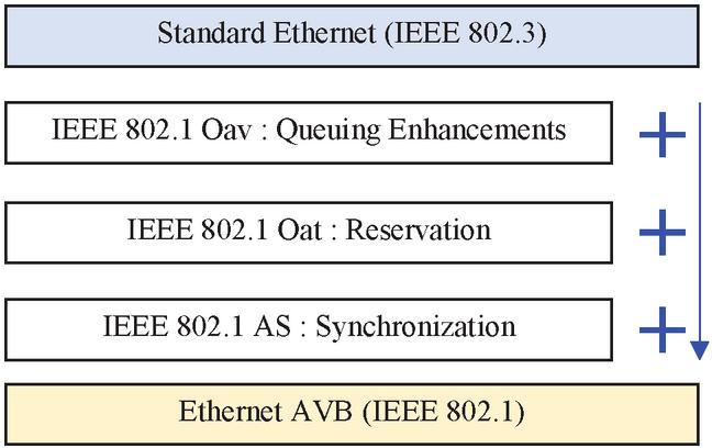
Figure 3 A standard of Ethernet AVB.
(3) Ethernet LANs (Local Area Network)
Individual LANs interconnect the Bridges, Talkers and Listeners. AVB extends the standard with three additional sub-standards in order to support time-sensitive automotive applications in asynchronous in-vehicle networks as shown in Figure 3.
• IEEE 802.1 Qav: Forwarding and queueing rules [2]
The method described in IEEE 802.1Q is used to separate time-critical and non-time-critical traffic into different traffic cases. The egress port buffers are separated into different queues, each assigned to a specific class. This separates low priority traffic from high priority traffic. Additionally, all egress ports have a credit-based shaping mechanism to prevent burst behavior.
• IEEE 802.1 Qat: Bandwidth reservation protocol [15]
It notifies reservation requests and defines a protocol for reserving resources for media streams. It allocates buffers within the switch to provide the required quality of service (QoS).
• IEEE 802.1 AS: Time synchronization protocol [16]
It describes time synchronization and is responsible for accurate time synchronization to the global time of network nodes.
• IEEE 1722: Stream transmission protocol
IEEE 1722 is the preferred AVB transport protocol. Encapsulates audio, video, or control data into Ethernet frames and adds presentation timestamps related to data processing time.
In case of audio or video data, 1722 transports the sample clock from the sender of a stream to the receiver. With the presentation time, the time of the video, or audio for being played is given to all of listeners. A synchronous playback could be arrived [17].
The eAVB includes a talker, a listener, and a bridge. The talker and listener share the gPTP (Generalized Precision Time Protocol) message. It is sent regularly to compensate time error. And the listener registers the VLAN (Virtual Local Area Network) and its own MAC (Media Access Control Address) address through MMRP (Multiple MAC Registration Protocol) and MVRP (Multiple VLAN Registration Protocol). The talker reserves the required bandwidth using the Multiple Stream Reservation Protocol (MSRP). To reserve resources, the talker advertises a message, and the bridge counts the resources available on the output port. The result is sent to the listener. If there are insufficient resources, the listener sends an error message. When the reservation is complete, the talker uses the IEEE 1722 protocol, the transport protocol, to transmit the streaming data to stream the necessary data in real time on the bridge-based local network. When a message containing IEEE 802.1 Qav is transmitted over Fast Ethernet, stream class A is transmitted within 2 ms per 7 hops. Stream class B is transmitted within 50 ms per 7 hops using forwarding and queuing rules [2, 7]. For QoS support, each node within AVB must support AVB standard, so AVB is not backwards compatible in terms of QoS, but it is compatible with standard Ethernet. The eAVB transmission protocol timestamps the transmitted video data and is activated through the global synchronization of the device so that the data transmission processing is executed at the same time. The stream reservation protocol standard IEEE 802.1Qat prevents packet loss, and IEEE 802.1Qav uses a traffic shaping mechanism to ensure timely delivery of time-sensitive traffic [17].
2.2.3 A synchronization between talker and listener
• Talker and Presentation Time
A Synchronization between talker and listener are crucial in the automotive system. In Figure 4, it explains how the media clock source is embedded into AVTP (Audio Video Transport Protocol) packets. The media clock’s source can be a simple free-running local oscillator, because the media clock does not need to lock to any reference, as long as the frequency of all media clocks in the same domain are synchronized. The media clock goes into a local timestamp generator that generates timestamps every certain number of media clock rising edges. These timestamps are generated based off of a local time reference. The Wall Clock then translates the local time based timestamps to gPTP timestamps. The AVTP Talker adds a fixed offset (typically the maximum delay between the Talker and all Listeners) and generates presentation timestamps. AVTP Presentation Time represents the gPTP time at which a given media sample, or event is sent to the time-sensitive application within each listener. This allows multiple listeners to display data at the same time, regardless of the listener’s location on the network. The AVTP presentation time tells the listener when to start processing the stream’s data (e.g. playing media) and is also used to recover the stream’s media clock [1].
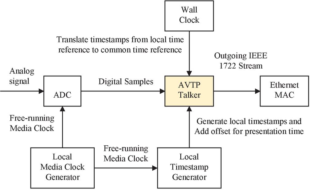
Figure 4 A block diagram of simplified AVB Talker.
With AVB, streaming data (e.g. camera data) can be transmitted with low latency and high quality. In vehicle AVB, IP, TCP and UDP are not essential because data is not transmitted across the entire network perimeter. AVB uses Ethernet directly. The AVB protocol is based on standards that are also available over IP, but for the reasons mentioned earlier, it is reduced and limited in dynamic response. This is for faster operation in the vehicle. In other words, dynamic bandwidth reservations using the Stream Reservation Protocol are not normally used in vehicles. In AVB, the data source is called the talker and the data sink is called the listener. A switch in the form of a coupling element is called a bridge, but it is not technically precise. Since a special MAC Multicast Address is used, in addition to the talker and listener, the switch must have AVB function and the “Forwarding and queuing for time-sensitive networks” system is operated. The PTP frame is also changed by the switch. Audio Video Transport Protocol (AVTP) transports individual data in the payload area. This typically contains video or audio data, but may also contain control data. When streaming data (audio/video) is transmitted, the AVTP header always contains a specific point in the future. In addition, AVTP uses VLAN tagged Ethernet frames to allow the switch to prioritize and keep the latency between talkers and listeners under 2ms. Another quality requirement for AVB is Low Latency Jitter. As soon as a certain point in the future is reached from the listener’s point of view, the frame is delivered by AVTP to the application layer. Very sophisticated synchronization of the nodes is required so that this point in time, called Presentation Time, can actually occur simultaneously on all received nodes. This is handled by the Precision Time Protocol (PTP), and in most cases the Generalized PTP (gPTP) variant is mainly used.
• Listener and Media Clock Synchronization
In Figure 5, it shows how a Listener extracts presentation timestamps and recovers the source media clock from incoming 1722 streams generated by a Talker. The period of the source media clock in the gPTP time base can be estimated by the time difference between two presentation timestamps divided by the number of samples in between. Continuously performing this calculation and applying appropriate filtering techniques will allow the system to accurately measure the media clock period of the source. Similarly, the local media clock generator output can be timestamped with local time base which is then translated to gPTP time base, and its period can also be accurately measured. After comparing the two clock periods, the Media Clock Recovery module continually generates to increment or decrement output frequency of the device so that the local media clock is synchronized to the source media clock [2].
3 A Proposed System Design of AVB
In this section, we present an architecture solution and introduces various system designs for in-vehicle communication. The most complex process in the simplest method that can be designed is expressed and the advantages of each are described.
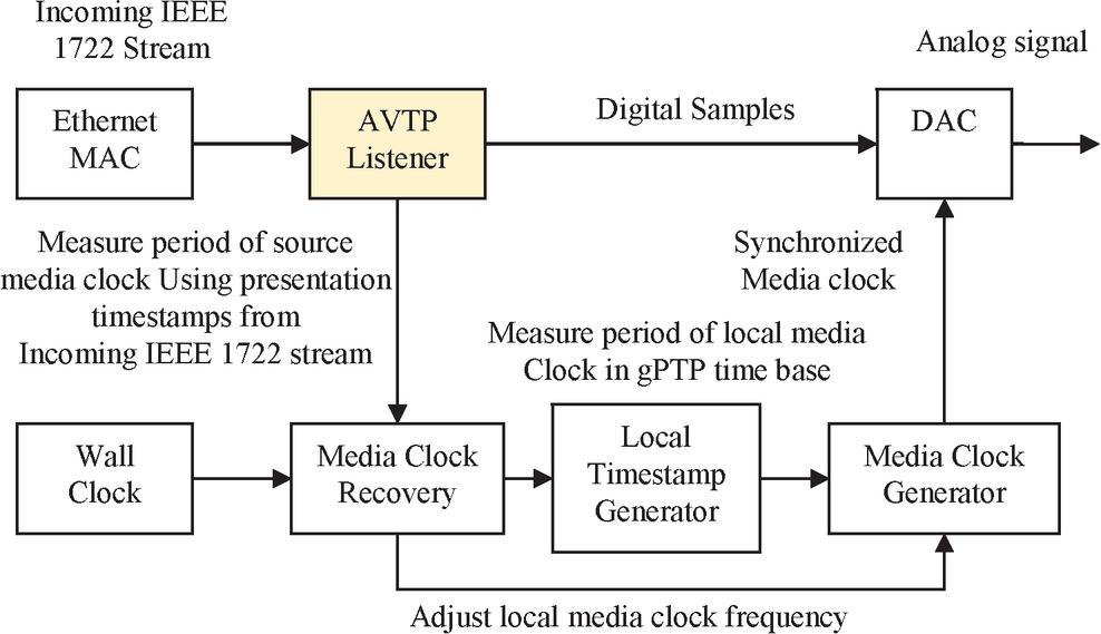
Figure 5 A block diagram of simplified AVB Listener.
3.1 A Design of Ethernet Camera with Display Device
As shown in Figure 6, it is the most suitable design for autonomous driving, and it is a design capable of showing real-time transmission rate most similar to the performance of the existing LVDS method. In this paper, by optimizing the settings of the encoder and AVB talker, we obtained a real-time video transmission rate comparable to that of the existing LVDS.
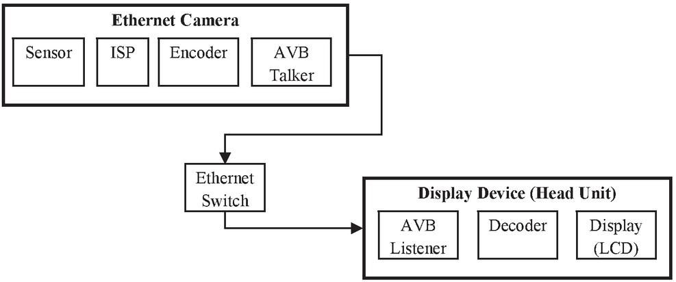
Figure 6 The connection between Ethernet camera and display device.
3.2 A Design of Non-display Device with Display Device
A specific device among the devices of the vehicle does not need an image, but in order to provide a user with a convenient control right, the head unit can control the device by providing the UI (User Interface) of the device as illustrated in Figure 7. The most important part is to transmit the UI in real time so that there is no difference between the user’s real-time UI response in the head unit’s LCD (Liquid Crystal Display) and that of the device.
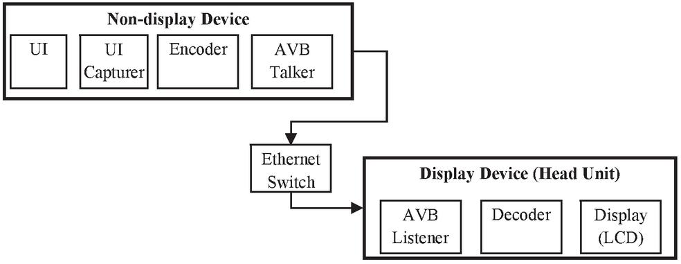
Figure 7 The connection between the non-display device and the display device for sharing the display (LCD).
3.3 A Design of Storage Device & An Antenna with Display Device
By receiving the compressed video through the storage device or the vehicle’s antenna and providing it to the UI of the Head Unit, the user can consume external contents as shown in Figure 8. At this time, the most important thing is to speed up the video transmission, and in this paper, the optimized talker setting enables faster video transmission than before.
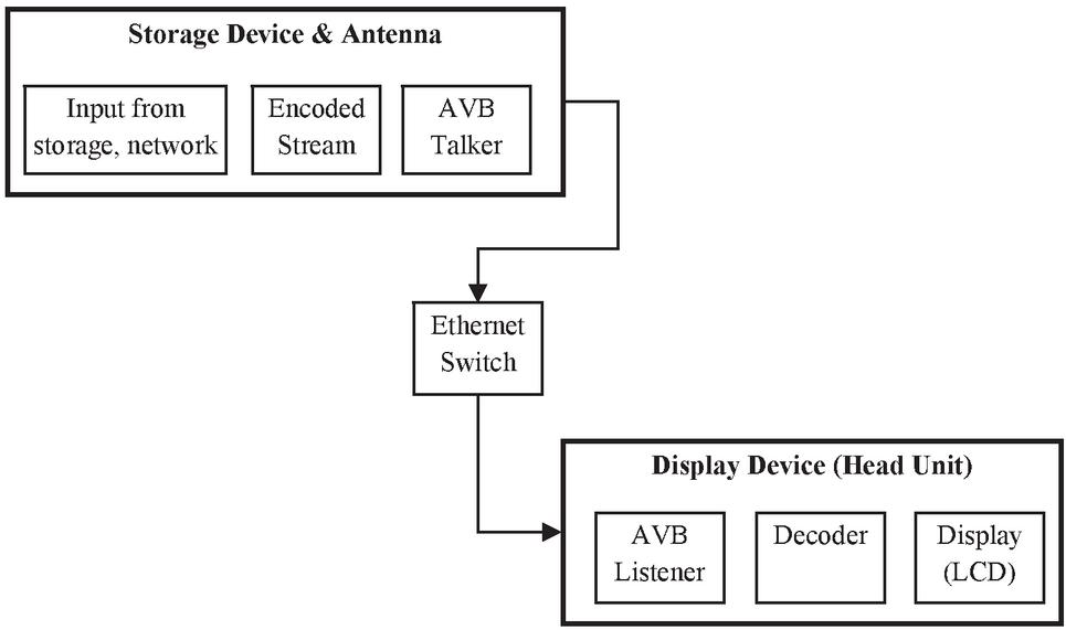
Figure 8 A data transmission between video/audio data of storage devices/antenna and the display device.
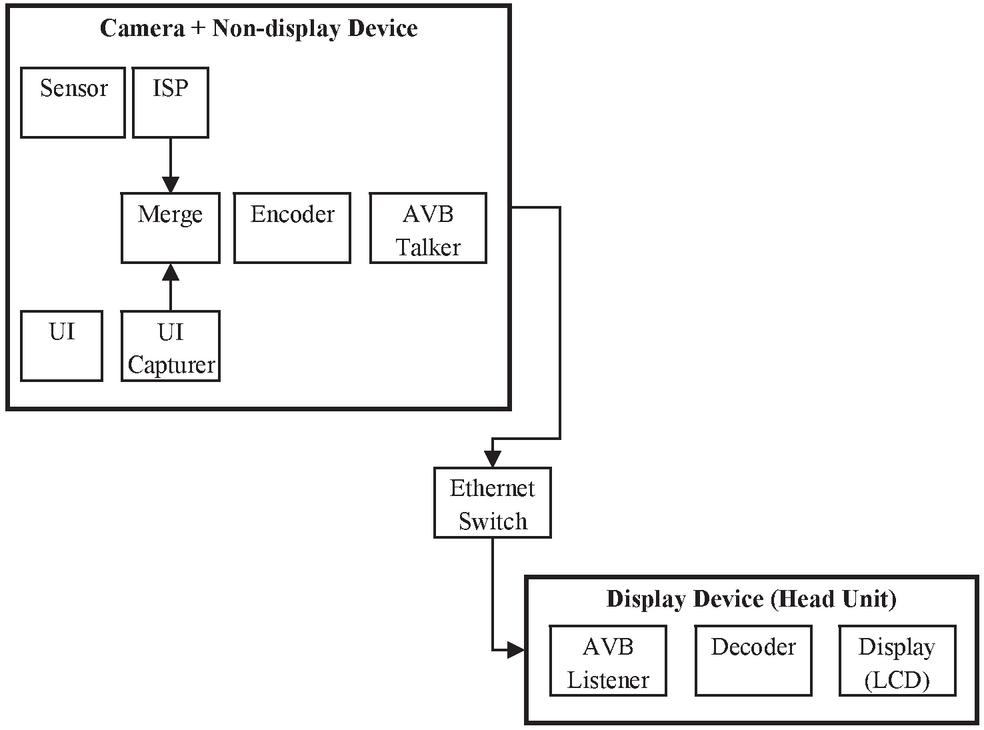
Figure 9 The connection between the non-display device belonging the camera and the display device.
3.4 A Design of Camera with Non-display Device
For example, in the case of a black box, it may be more advantageous to share the display inside the vehicle than to have a display. In this paper, we identified that it takes a lot of time in the process of merging camera images and UI, and real-time image transmission is possible through optimized GPU settings as described in Figure 9.
3.5 A Design of Reduced Latency Machine to Machine In-vehicle
When designing a vehicle, there may be cases where an image from a camera is required, but the device does not have a camera, or an external camera is used because the device does not have an ISP due to unit cost. In the case of a specific device, there may be a situation where an external camera image is required because there is a UI and an image from the camera is required. Through the three methods proposed in this paper: GPU, Encoder, and transmission optimization, high improved results were obtained even in the most complex situations.
We present an architecture solution as shown in Figure 10. It illustrates between components in automotive environment. The data stream is transmitted in the form of eAVB from the Ethernet camera, USB, and Antenna, and the data can be transmitted directly to each device, or to a device such as a head unit through an Ethernet switch. As depicted in Figure 10, when data such as audio/video is sent directly to the head unit, the delay can be reduced. However, when other multimedia devices share the display with the head unit, a merge process of Camera’s video and UI causes a big delay. In a vehicle, it is expected to increase the number of sharing a limited display with various multimedia because it’s not practical to provide a display for every multimedia device unless it’s a high-end car. As a result of actual experiments, merge the images by sharing the display as above, the H/U’s display showed about twice as much delay as the image received directly from the camera.
In the next section 4, we present our outstanding ideas.
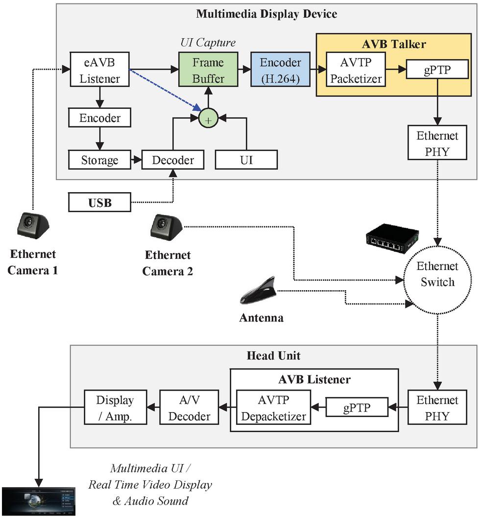
Figure 10 A design of reduced latency machine to machine in-vehicle environment between multimedia display device and head unit, blue dotted line is a real-time camera video transmission without recording.
4 GPU Algorithm Optimization Design for Automotive
This section describes the concept of UI capture and the proposed algorithm of GPU optimization.
4.1 A Concept of UI Capture
The overall design of a data center can be classified in 4 categories Tier I-IV each one presenting advantages and disadvantages related to power consumption and availability [18, 19]. In most cases availability and safety issues yield to redundant N1, N2 or 2N data center designs and this has a serious effect on power consumption. According to Figure 2.1, a data center has the following main units.

Figure 11 A concept of UI Capture.
In Figure 11, the overall details of UI capture are visualized. UI refers to the user interface and generally refers to a picture provided for users on the display in an application. For example, it could be icons, pictures, and texts. Recently, all these things are simply expressed as UI. The reason for capturing the UI is that in the case of a device without a display, the data in the frame buffer cannot be used in the device. The device can be used for storing a UI or image, or it can send a UI and an image to another device in real time to show the image of the device through the display of another device. The reason for doing this is because the vehicle’s equipment is limited, as explained earlier. In this paper, since verification was not performed in an actual vehicle, a design was proposed in consideration of the current state of the overall technology. Therefore, in this paper, real-time transmission of video was performed by other devices, and it was not possible to control UI in real time by receiving, for example, screen input values from other devices. Nevertheless, it is expected that real-time control in the vehicle expected in the future will be possible by changing the image of the camera in real time and the UI screen arbitrarily.
Explaining the overall flow, the UI created in the application is changed in real time according to the user’s input. These UI screens are stored in the frame buffer through the graphic driver. In this case, using a GPU can perform faster processing than using a CPU. In parallel, an external camera or a stored image may be decoded and stored in a frame buffer. For example, in recent vehicles, there are cases of parking assistance systems and autonomous driving that view UI and camera images on the screen in real time. In this way, the UI stored in the frame buffer is captured through the GPU. This is defined as UI capture. The captured UI is compressed through a video encoder and transmitted to an external device through the AVB protocol. The external device can receive the transmitted image and output it to the screen through the display device in real time.
In the next chapter, we introduce a method of optimizing the GPU algorithm that can reduce the delay of the image caused by UI capture procedure.
4.2 The Optimization of GPU Algorithm
Through actual experiments between vehicle devices, we propose an optimized design. Figure 12 illustrates a simplified representation of the proposed system. In the embedded multi-core ARM environment, the test results show that the CPU usage increases more than 65% when the AVB talker is running. In this situation, increasing the usage of CPU was considered undesirable, the experiment result shows that optimizes GPU can reduce the latency. It is important that the GPU acceleration meets the requirements of automotive applications while reducing resource usage of UI capture and audio/video encoding. We adopted GPU acceleration algorithm with minimal increase in CPU usage [18]. By accelerating and optimizing GPU, it dramatically decreases the time of capturing UI as shown in Figure 13. The existing method used the GPU without optimizing when capturing the UI, so there was a situation where there was a relatively high delay in video transmission. There may be cases where only the UI image is used for UI capture, and there may be cases where the UI image and the camera image are combined. In both cases, the concept of storing raw video image data in the frame buffer into the buffer through the GPU is the same. The captured UI buffer stored in this way is delivered to the video encoder for H.264 compression. The compressed video is packetized according to the AVTP format. The purpose of this process is to capture UI and video images in the frame buffer in real time through GPU optimization.
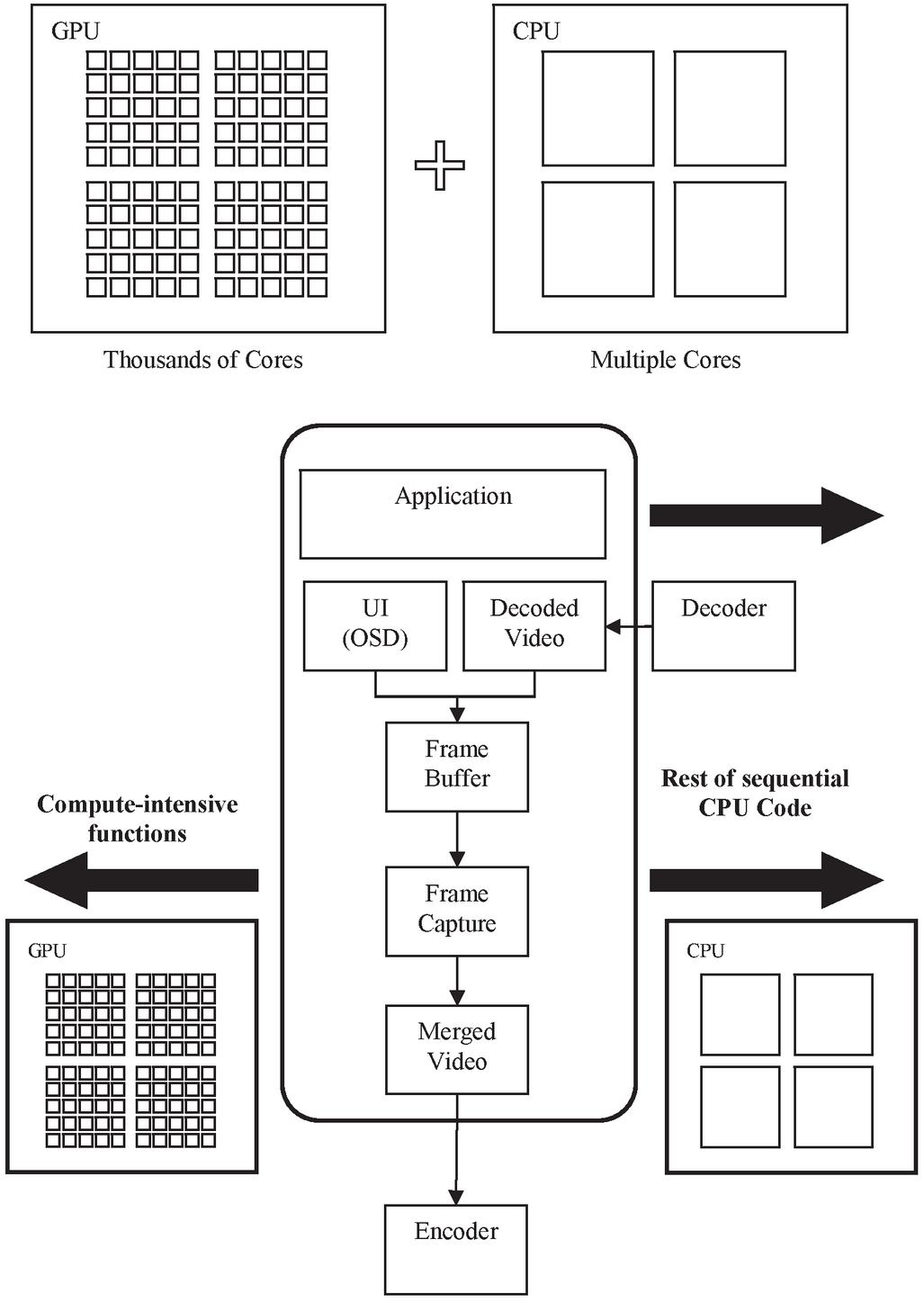
Figure 12 An acceleration and an optimization of GPU.
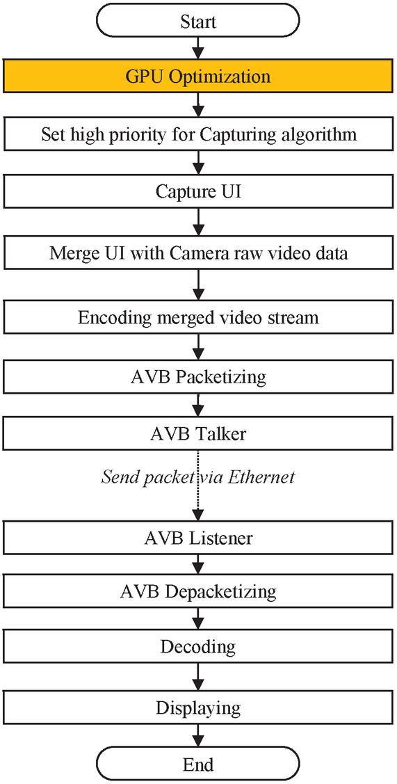
Figure 13 A proposed RLMM flowchart of GPU optimization.
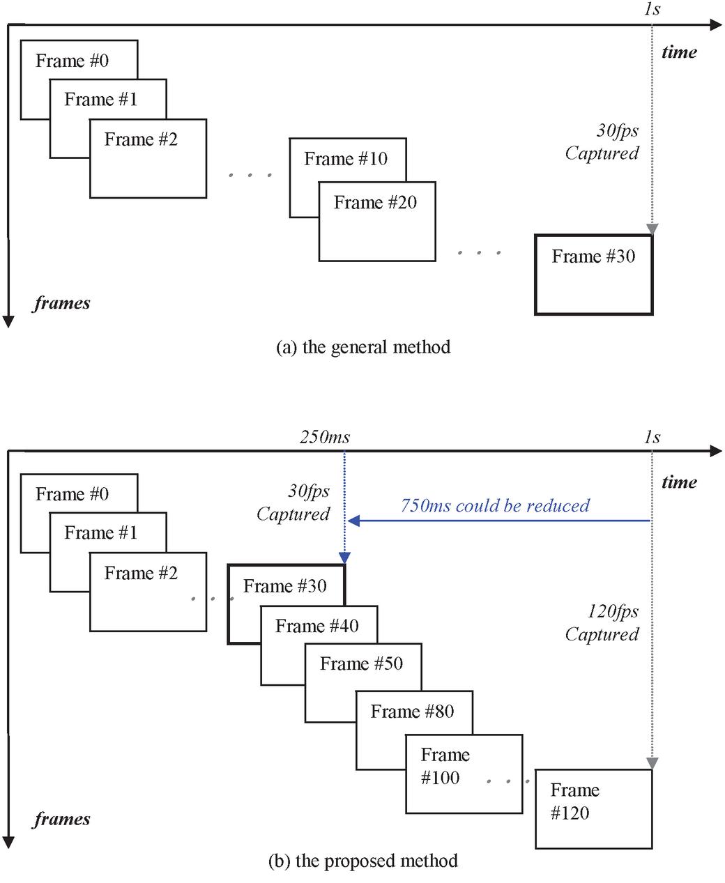
Figure 14 A concept of suggested GPU Acceleration of capturing frames.
In this paper, we suggest the GPU acceleration that the basic concept of GPU acceleration of capturing frames are described as shown in Figure 14. In general, the frames are captured at the frame buffer in proportion to the input image. If the input is 30 fps, the captured frames could be 30 fps. We found that the usage CPU is increased during the 30 fps capture procedure while the usage of GPU is used than we are expected. We have investigated the optimization of system if there is any way to reduce the latency by using the GPU. The proposed capturing of frame method shows that it captures four times more frames at the same time (1 s) than before. After capturing 120 fps, we dropped it into 30 fps. The result shows that the proposed algorithm is possible to reduce the capture time by 4 times, Equation (1), (FC(t): Frame Capture Time)
| Original Capture Time: FC(t) | (1) |
| Proposed Capture Time: FC(t)/GPU acceleration time |
Considering a simple concept, if 30 fps is secured from 1 second to 250 ms and transmitted to the video encoder, the speed of securing video can be very high. However, the problem is that the 750 ms frame is dropped, so there may be a case where the image does not look smooth from the user’s subjective point of view. In particular, in a fast-moving car, this video image loss can cause a very serious accident.

Figure 15 A proposed GPU algorithm optimization method.
Figure 15 illustrates the proposed GPU algorithm optimization. Figure 15-(a) shows the existing frame capture method and the corresponding payload of the video encoder. Since the conventional method captures 30 frames for 1 second, the encoder has a structure that has no choice but to receive and process one frame as a buffer every time a frame is captured. Figure 15-(b) is the proposed method. Unlike the existing method, when capturing frames at 120 fps, 30 frames of video are secured in about 250 ms. Therefore, video encoder can compress video faster than before. The problem is that about 750 ms of video loss can occur during 250 ms–1 s.
In this paper, the 30th frame is defined as the Candidate I-frame (CI-1) to solve the loss. In the structure of the existing i-frame and p-frame, the 96th frame, which is the same as the 24th, which is the point at which it becomes the second i-frame, is specified as the Candidate I-frame 2 (CI-2). The i-frame is an intra frame (picture) of MPEG, and the p-frame is a predictive frame (inter frame/picture) [19]. I-frame is compression in space, and p-frame is compression in time between reference frames using i-frame as a reference frame. With this structure, the i-frame plays a very important role in determining the video quality. After comparing the images of CI-1 and CI-2, if the loss of the image is not large, CI-1 is used as the last frame of 30 fps. Finally, we were able to improve the UI capture time and the speed of the video encoder by dropping 750ms between 250 ms and 1 s.
There may be many ways to compare images, but in this paper, images are compared using MSE (Mean Squared Error), and PSNR (Peak Signal-to-Noise Ratios). Therefore, comparison of the frames of CI-1 and CI-2 was also performed using MSE and PSNR. PSNR and MSE which are calculation methods used for image comparison, are briefly described as follows [29].
• Mean square error (MSE)
MSE is known as the pixel square of the differences between the two images’ respective pixels. The mean square error (MSE) of N * M size image is given by Equation (2).
| (2) |
where, m is number of rows and n is columns in the input images.
• PSNR (Peak Signal to Noise Ratio)
PSNR is an engineering term for the ratio of a signal’s highest potential output to the power of corrupting noise that influences fidelity. PSNR is a metric that measures the peak error between the compressed and original image. The higher the PSNR rating, the better the picture quality. MSE is first calculated before PSNR is calculated. The MSE represents the total difference between the compressed and original image. MSE with a low value increases image quality thereby lowering error as Equation (3).
| (3) |
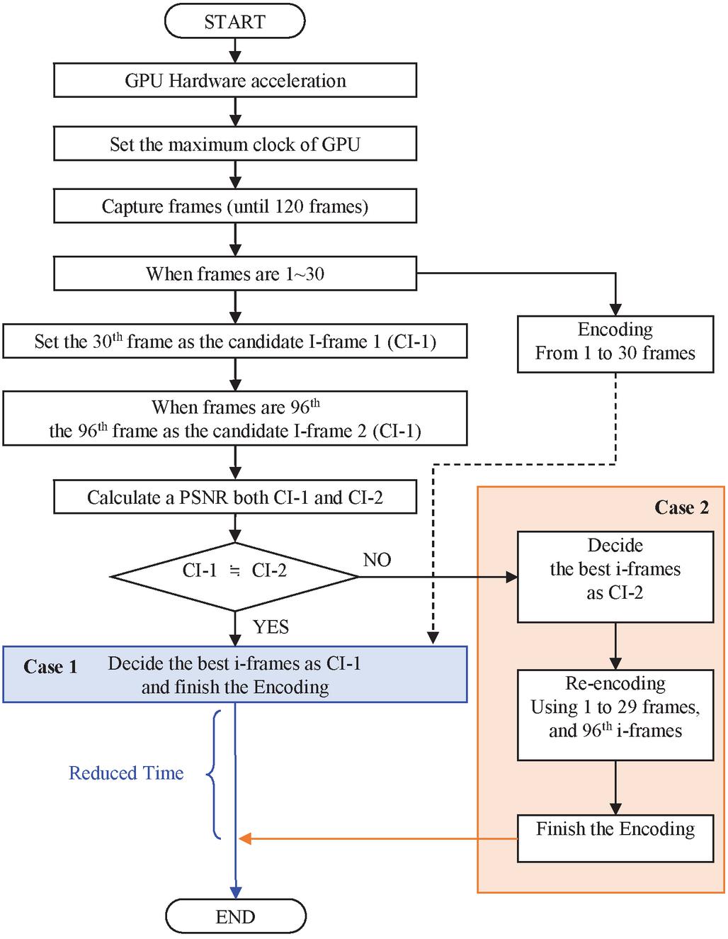
Figure 16 A flowchart of the proposed GPU algorithm optimization.
As shown in Figure 16, we designed a flow chart of the proposed GPU algorithm optimization. As described in Section 4.3, first, GPU acceleration is performed to achieve basic optimization performance. After that, UI capture is performed as described above, and among them, the i-frame candidate for CI-1 is set. At the time of setting CI-1, start the video encoder in parallel. During video encoding including CI-1, CI-2 is captured for UI capture. After calculating the MSE and PSNR of CI-1 and CI-2, the respective values are compared. If the PSNR values of CI-1 and CI-2 are within 5%, the candidate i-frame is selected as CI-1. Conversely, when the PSNR comparison result of CI-1 and CI-2 is more than 5%, CI-2 is selected using CI-2 as the candidate i-frame.
It can be expressed as Equation (4).
| CI-1 | (4) | |
| CI-1 |
Where,
Case 1 is the difference of PSNR is within 5%
Case 2 is the difference of PSNR is more than 5%
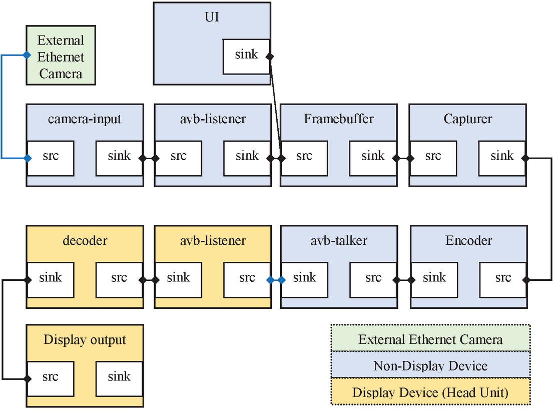
Figure 17 A system pipeline structure of Gstreamer among AVB devices.
As a result, in the case of case 1, a faster result than the case 2 was obtained because the video encoder and the video encoder were executed in parallel. Case 2 did not show much difference from the existing method. As a result of the experiment, there were many cases that were selected as case 1, and it was confirmed that the overall system performance was greatly improved. The reason for this result is that the amount of change in the UI is not large compared to the general video. Although case 2 can be selected instantaneously, the overall system showed a small frequency. In the case of the video, the same result was shown, because, considering our driving environment, the situation and video in front and rear do not change significantly unless we are driving recklessly.
4.3 GPU Hardware Acceleration
Most GPUs have HW acceleration. Recent GPUs perform operations by adjusting the operation clock according to the load situation of the system. On the surface, it is expected to be able to operate properly according to the load of the system. However, the basic GPU operation is a part set by the chipset company as default. These default values are not set as the best performance in consideration of the worst possible external situations. For example, considering the heat of the system, if the GPU accelerates using a high clock and operates unnecessarily, the process of requesting complains and correction from the chipset manufacturer may occur. Considering this situation, for example, if the maximum clock of the GPU is marked as 1000 MHz in the specification, it operates according to the system load up to about 500 MHz. In order to use more clocks, it is most likely that the application needs to control the GPU. As described above, it is chipset makers that make GPUs, but it is the manufacturer or user that uses them. In products designed and built by users, it is essential to accelerate and tune the GPU according to the situation. It is suggested in this paper to set the usage of these GPUs according to the specifications of the products currently in use as much as possible. The specifications of the GPU used in the experimental environment in this paper are Adreno 615, 64bit, and 780 MHz. In this paper, since the experiment was not performed in an actual vehicle but was configured in a benchmark environment, the GPU was accelerated to the maximum and the clock was set to 780 MHz. As described above, it is suggested to consider and set it according to the load of the system to be designed.
In Section 5, the experimental results for the proposed method are described in consideration of various situations.
5 Experimental Results
5.1 Test Environment
In this paper, we designed to be able to test the various AVB systems introduced in the previous section. As explained in Figure 17, the test environment for the external camera, the non-display device, and the display device (head unit) among several systems is described. Linux-based equipment was used for HW, and Opensource Gstreamer was used for SW to create pipelines for each structure. Table 1 describes the experimental environment and specifications.
5.2 A Result of Optimized Latency
To explore the feasibility of using Ethernet AVB, we developed a device model for comparing, validating, and evaluating Ethernet AVB’s real-time performance to the current Ethernet standard. [2, 3] In Section 4, we visualize the components and the test device model layout that consider the appropriate hardware and software components for the communication. The network consists of one Ethernet switch, and a variety of computers. The switch and devices are linked through a full duplex link.
Table 1 The test environment and specifications of devices
| Devices | Components | Specifications |
| Ethernet Camera | Resolution | H.264 (19201080p@30fps) |
| LVDS Camera | Resolution | H.264 (19201080p@30fps) |
| LVDS to HDMI Converter | Resolution | H.264 (19201080p@30fps) |
| Ethernet Switch | Speed | 10/100/1000 Mbps |
| Multimedia Device (Qualcomm Evaluation Kit) | CPU | QCS605, Kryo 300, Octa-core, 64bit, 2.5GHz |
| GPU | Adreno 615, 64bit, 780 MHz | |
| DDR | 4GB (LPDDR4) | |
| Video Encoder | H.264 (19201080p@30fps) | |
| Video Decoder | H.264 (19201080p@30fps) | |
| OS | Kernel 4.x (Android Oreo 8.1) | |
| Gstreamer | v1.14.5 | |
| Computer Language | C/C/Shell Script | |
| SDK | Provided by EVK | |
| Head Unit (PC) | CPU | Intel(R) Core (TM) i7-8550U, 1.80 GHz |
| DDR | 16GB (LPDDR4) | |
| GPU | NVIDIA QUADRO P2000 (Memory 5GB GDDR5, i/f 160-bit, B/W 140GB/s, CUDA Cores 1024) | |
| OS | Ubuntu v18.04 LTS | |
| NVIDIA SMI Driver | v440.000 | |
| NVIDIA CUDA | V10.2.89 | |
| NVIDIA Video Codec SDK | V9.0.20 | |
| Gstreamer | v1.14.5 | |
| Computer Language | C/C/Shell Script |
Table 2 The comparison between the LVDS camera and Ethernet camera
| LVDS | Ethernet | Difference | |||
| Device | Component | Camera (ms) | Camera (ms) | Latency (ms) | |
| Camera | 45 | 59 | 14 | 31.11% | |
| LVDS i/f/Ethernet Switch | 1 | 1.3 | 0.3 | 30% | |
| H/U | AVB Listener | – | 15 | 15 | 15% |
| Decoder | 22 | 22 | – | – | |
| Display | 5 | 5 | – | – | |
| Total Latency | 73 | 102.3 | 29.3 | 40.14% | |
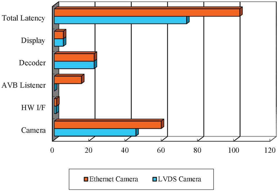
Figure 18 The comparison between the LVDS camera and Ethernet Camera.
Table 3 The result between Non-display multimedia device and H/U
| Without | Proposed | Reduced | |||
| Device | Component | RLMM (ms) | RLMM (ms) | Latency (ms) | |
| Multimedia | UI video | 25 | 7 | 18 | 72% |
| Device | UI Capture | 117.2 | 15 | 102.2 | 87.2% |
| Video Encoder | 62 | 62 | – | – | |
| AVB Talker | 52 | 52 | – | – | |
| Ethernet Switch | 1.4 | 1.4 | – | – | |
| H/U | AVB Listener | 11 | 11 | – | – |
| Decoder | 21 | 21 | – | – | |
| Display | 5.5 | 5.5 | – | – | |
| Total Latency | 295.1 | 174.9 | 120.2 | 40.73% | |
The comparison between the LVDS and Ethernet camera is presented in Table 2. The existing LVDS camera is generally seen to be capable of real-time transmission than ethernet cameras. If a camera is built-in, real-time processing will be possible faster than LVDS when transmitted via MIPI-CSI (Mobile Industry Processor Interface Camera Serial Interface). In this paper, the performance of the Ethernet camera was confirmed and improved in advance in consideration of a case where an autonomous driving camera is not separately used but one camera is used in common in order to lower the unit price in the future. When comparing the external camera interface LVDS and Ethernet camera, the delay in the camera was about 31.11% faster with LVDS of 45 ms and ethernet camera of 59 ms. In the interface, LVDS showed about 30%, especially the Ethernet camera using AVB showed 15% performance delay.
Overall, LVDS achieved a result capable of real-time transmission than about 40.14% Ethernet camera as shown in Figure 18.
The purpose of the paper was to improve the performance of the Ethernet camera. Table 3 shows the results of the method proposed in the previous Sections 4. The experimental environment was the same. The results were separated by whether the proposed RLMM algorithm was applied, or not. The experiment was conducted in which a device without a display transmits the UI and the recorded video already stored to the head unit with the display. When using RLMM, performance improvement of 72% was achieved in UI and video merging. In UI capture, it took 117.2 ms when not using RLMM, but RLMM showed a surprising improvement of 87.2%, which took 15 ms. Through the optimized method, the overall latency is reduced about 40.73% as illustrated in Figure 19.

Figure 19 The result between Non-display multimedia device and H/U.
Table 4 The latency of eAVB, end-to-end delay of each components
| Without | Proposed | Reduced | |||
| Device | Component | RLMM (ms) | RLMM (ms) | Latency (ms) | |
| Ethernet Camera | 59 | 59 | – | – | |
| Ethernet Switch | 1.3 | 1.3 | – | – | |
| Multimedia | AVB Listener | 15 | 15 | – | – |
| Device | UI Camera video | 26 | 8 | 18 | 69.23% |
| UI Capture | 115.3 | 17.5 | 97.8 | 84.82% | |
| Video Encoder | 65 | 65 | – | – | |
| AVB Talker | 55 | 55 | – | – | |
| Ethernet Switch | 1.5 | 1.5 | – | – | |
| H/U | AVB Listener | 12 | 12 | – | – |
| Decoder | 25 | 25 | – | – | |
| Display | 5.7 | 5.7 | – | – | |
| Total Latency | 380.8 | 265 | 115.8 | 30.41% | |
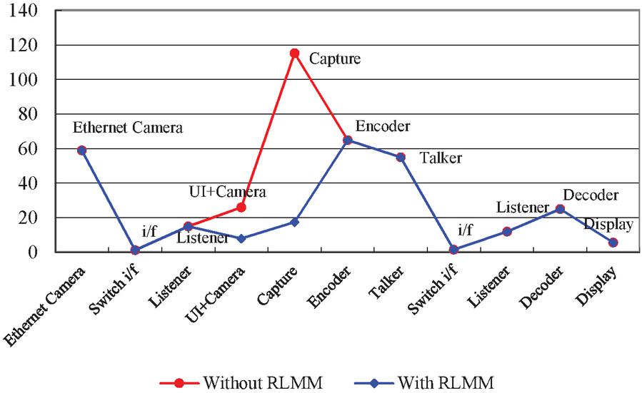
Figure 20 The result of optimized latency of eAVB.
Table 5 The objective result of decoded video streams
| Average PSNR (dB) | ||||
| Decoded Frames | Original Method | Proposed RLMM | (dB) | (%) |
| 1–30 | 35.25 | 35.21 | 0.04 | 0.11 |
| 31–60 | 35.24 | 35.19 | 0.05 | 0.14 |
| 61–90 | 35.38 | 35.22 | 0.16 | 0.45 |
| 91–120 | 35.23 | 35.17 | 0.06 | 0.17 |
| 121–150 | 35.19 | 35.09 | 0.1 | 0.28 |
| 151–180 | 35.12 | 35.05 | 0.07 | 0.20 |
| 181–210 | 35.09 | 35.01 | 0.08 | 0.23 |
| 211–240 | 35.23 | 35.18 | 0.05 | 0.14 |
| 241–270 | 35.33 | 35.25 | 0.08 | 0.23 |
| 271–300 | 35.11 | 35.02 | 0.09 | 0.26 |
| Total Average | 35.22 | 35.14 | 0.08 | 0.22 |
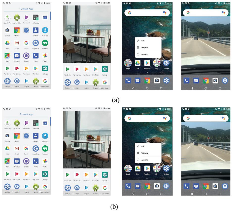
Figure 21 The subjective result of decoded video streams, (a) original results, (b) proposed RLMM’s results.
The experiment findings of using external camera, non-display device and display device are presented in Table 4. Looking at the difference between without RLMM and with RLMM shown in Figure 20, the merge process of UI and camera images took 22 ms, UI capture 115.3 ms, Video encoder 65 ms, and AVB talker 55 ms respectively. It showed the same level except for the latency of the multimedia device. According to our reliable experimental results, we obtained 8 ms for UI and camera video merge video, 17.5 ms for the UI capture.
Significant improvement of 18 ms (69.23%) in the UI and the camera video merge, 97.8 ms (84.82%) in the UI capture. The end-to-end processing time with the same payload is significantly less than the initial version as described in Table 5. Overall, the proposed RLMM method achieved about 30.41% performance improvement in total system.
Table 5 shows the objective evaluation results that the values of the original method and the proposed RLMM were compared. The average PSNR values from 1 to 30 frames were obtained based on 30 fps, respectively. The obtained values were compared with the original method and the proposed RLMM method. When comparing the overall average value, the existing method showed a value of 35.22 dB and the proposed method showed a value of 35.14 dB. The proposed method showed a PSNR reduction of about 0.22% compared to the existing method. Figure 21 shows the subjective evaluation results for cases where only UI is transmitted, when UI and real-time camera images are merged and transmitted, when the UI screen is switched, and when UI and recorded images are merged and transmitted. As a result of subjective evaluation, it was confirmed that the PSNR reduction of 0.22% confirmed in the objective evaluation result is not a number that can give a big difference to users. According to the experimental results, frame drop may occur when optimizing the GPU algorithm described in the Section 4, but there was no significant image loss in the experimental environment proposed and measured in this paper. It is expected that some image loss may occur if the image moves very fast in the actual vehicle.
6 Conclusion & Future Work
In this paper, we have presented and investigated the latency of AVB network and suggested the optimized design of embedded system. The focus of this investigation lay on the influence of reducing delay between components. The proposed RLMM on realistic cases illustrated that there was a delay reduction about 30.41%. It is expected that the suggested method for the actual automotive environment can greatly shorten the time period in the design and development process. We not only presented a proof of latency analysis for AVB, but the alternative solution on practical test cases has also been tested. It is expected that the proposed method for a real automotive environment can significantly reduce the time in the design and development process. In-vehicle multimedia cameras generally use 2M (19201080), and this paper was also experimented with 2M standards. The suggested algorithm is expected to make a greater contribution when images of 8M (38402160) or more are introduced into the vehicle in the future. could make in Vehicle Network Environment. Through the proposed real-time camera and video streaming via optimized settings of AVB system, it is expected that AI algorithms in autonomous driving will be of great help in understanding and analyzing images in real time. Consequently, it should be paid attention to it in design of future transmission with low latency for automotive.
In future work, it is expected that it would be good to do something to improve the areas that were insufficient, which was the goal. As a result, it is possible to transmit the video transmission speed in real time rather than the conventional method in the overall AVB system of the proposed vehicle as described in Section 7. However, it is true that there is a video delay than the aimed LVDS or single Ethernet camera system. In the future, we plan to do our best to enable real-time video transmission at a single level of LVDS or Ethernet Camera.
Acknowledgment
This work was supported by the National Research Foundation of Korea (NRF) grant funded by the Korea government (No. NRF-2020R1A2C200917).
References
[1] IEEE Standard for Local and metropolitan area networks, “Audio Video Bridging (AVB) Systems,” in IEEE Std 802.1BA-2011, vol., no., pp. 1–45, 30 Sept. 2011.
[2] IEEE Standard for Local and Metropolitan Area Networks, “Timing and Synchronization for Time-Sensitive Applications in Bridged Local Area Networks,” in IEEE Std 802.1AS-2011, vol., no., pp. 1–292, 30 March 2011.
[3] J. Eveleens, “Ethernet AVB Overview and Status,” SMPTE 2014 Annual Technical Conference & Exhibition, Hollywood, CA, USA, 2014, pp. 1–11.
[4] C. Herber, A. Saeed and A. Herkersdorf, “Design and Evaluation of a Low-Latency AVB Ethernet Endpoint Based on ARM SoC,” 2015 IEEE 17th International Conference on High Performance Computing and Communications, 2015 IEEE 7th International Symposium on Cyberspace Safety and Security, and 2015 IEEE 12th International Conference on Embedded Software and Systems, New York, NY, 2015, pp. 1128–1134.
[5] T. Nolte, H. Hansson and L. L. Bello, “Automotive communications-past, current and future,” 2005 IEEE Conference on Emerging Technologies and Factory Automation, Catania, 2005, pp. 8–992.
[6] R. Queck, “Analysis of Ethernet AVB for automotive networks using Network Calculus,” 2012 IEEE International Conference on Vehicular Electronics and Safety (ICVES 2012), Istanbul, 2012, pp. 61–67.
[7] J. Park, B. Cheoun and J. Jeon, “Worst-case analysis of ethernet AVB in automotive system,” 2015 IEEE International Conference on Information and Automation, Lijiang, 2015, pp. 1696–1699.
[8] X. Liu, Z. Nie, D. Li and H. Yu, “Design of An Improved Ethernet AVB Model for Real-time Communication in In-Vehicle Network,” 2019 IEEE 3rd Information Technology, Networking, Electronic and Automation Control Conference (ITNEC), Chengdu, China, 2019, pp. 6–10.
[9] D. An, “Design and implementation of the car multimedia data transmission system using Ethernet AVB,” 2016 Eighth International Conference on Ubiquitous and Future Networks (ICUFN), Vienna, 2016, pp. 481–483.
[10] O. Kleineberg, P. Fröhlich and D. Heffernan, “Fault-tolerant Audio and Video Bridging (AVB) Ethernet: A novel method for redundant stream registration configuration,” Proceedings of 2012 IEEE 17th International Conference on Emerging Technologies & Factory Automation (ETFA 2012), Krakow, 2012, pp. 1–8.
[11] L. Zhao, P. Pop, Z. Zheng and Q. Li, “Timing Analysis of AVB Traffic in TSN Networks Using Network Calculus,” 2018 IEEE Real-Time and Embedded Technology and Applications Symposium (RTAS), Porto, 2018, pp. 25–36.
[12] J. Imtiaz, J. Jasperneite and L. Han, “A performance study of Ethernet Audio Video Bridging (AVB) for Industrial real-time communication,” 2009 IEEE Conference on Emerging Technologies & Factory Automation, Mallorca, 2009, pp. 1–8.
[13] F. Reimann, S. Graf, F. Streit, M. Glaß and J. Teich, “Timing analysis of Ethernet AVB-based automotive E/E architectures,” 2013 IEEE 18th Conference on Emerging Technologies & Factory Automation (ETFA), Cagliari, 2013, pp. 1–8.
[14] S. Jeon, J. Lee and S. Park, “Dual-path method for enhancing the performance of IEEE 802.1 avb with time-triggered scheme,” 2015 21st Asia-Pacific Conference on Communications (APCC), Kyoto, 2015, pp. 519–523.
[15] Virtual Bridged Local Area Networks – Amendment 9: Stream Reservation Protocol (SRP), IEEE P802.1Qat/D6.1 edition, June 2010.
[16] Virtual Bridged Local Area Networks – Amendment 12: Forwarding and Queuing Enhancements for Time-Sensitive Streams, IEEE P802.1Qav/D7.0 edition, October 2009.
[17] A. Kern, H. Zinner, T. Streichert, J. Nöbauer and J. Teich, “Accuracy of Ethernet AVB time synchronization under varying temperature conditions for automotive networks,” 2011 48th ACM/EDAC/IEEE Design Automation Conference (DAC), New York, NY, 2011, pp. 597–602.
[18] J. M. Ready and C. N. Taylor, “GPU Acceleration of Real-time Feature Based Algorithms,” 2007 IEEE Workshop on Motion and Video Computing (WMVC’07), Austin, TX, USA, 2007, pp. 8–8.
[19] B. An, Y. Kim and O. Kwon, “Low-Complexity Motion Estimation for H.264/AVC Through Perceptual Video Coding,” KSII Transactions on Internet and Information Systems, vol. 5, no. 8, pp. 1444–1456, 2011.
[20] D. Chai and K. N. Ngan, “Foreground/background video coding scheme,” ISCAS’97., Proceedings of 1997 IEEE International Symposium on, vol. 2, pp. 1448–1451, 1997.
[21] R. R. Knipling et al., “Assessment of IVHS countermeasures for collision avoidance systems,” National Highway Traffic Safety Administration, Washington, DC, USA, Tech. Rep. DOT HS 807 995, May 1993.
[22] T. Kim and H. Jeong, “A Novel Algorithm for Crash Detection Under General Road Scenes Using Crash Probabilities and an Interactive Multiple Model Particle Filter,” in IEEE Transactions on Intelligent Transportation Systems, vol. 15, no. 6, Dec. 2014.
[23] B. An, Y. Kim, “Improved Crash Detection Algorithm for Vehicle Crash Detection,” KSDT vol. 19, no. 3. pp. 93–99, 2020.
[24] T. Cohrs and L. Treybig, “Array microphones and signal processing within an ethernet-based AVB network,” 2016 IEEE 6th International Conference on Consumer Electronics - Berlin (ICCE-Berlin), 2016.
[25] M. Kim, Y. Jang, M. Jung and S. Kim, “Frame Forwarding Rules for Link Utilization in IEEE 802.1 AVB Networks,” 2008 International Conference on Advanced Language Processing and Web Information Technology, 2008.
[26] H. Lee, J. Lee, C. Park and S. Park, “Time-aware preemption to enhance the performance of Audio/Video Bridging (AVB) in IEEE 802.1 TSN,” 2016 First IEEE International Conference on Computer Communication and the Internet (ICCCI), 2016.
[27] H. J. Rivera Verduzco, P. J. L. Cuijpers and J. Cao, “Work-in-Progress: Best-Case Response Time Analysis for Ethernet AVB,” 2017 IEEE Real-Time Systems Symposium (RTSS), 2017.
[28] Y. S. Lee, J. H. Kim and J. W. Jeon, “FlexRay and Ethernet AVB Synchronization for High QoS Automotive Gateway,” in IEEE Transactions on Vehicular Technology, vol. 66, no. 7, pp. 5737–5751, July 2017.
[29] Ms. M. Manju, P. Abarna, U. Akila, S. Yamini, “Peak Signal to Noise Ratio & Mean Square Error calculation for various Images using the lossless Image,” International Journal of Pure and Applied Mathematics, Volume 119, No. 12, 2018, 14471–14477, 2018.
Biographies

Byoungman An received the B.S. and M.S. in Electronics & Electrical Engineering from Dankook University, Korea in 2010 and 2012, respectively. He is also currently pursuing an Ph.D. degree in the school of Electrical & Electronics Engineering. His research interests include image/video compression, automotive network, in-vehicle network and image processing.
Youngseop Kim received the M.S in Computer Engineering from the University of Southern California in 1991, and the Ph.D. in Electronic Systems from Rensselaer Polytechnic Institute in 2001. He was a manager at Samsung SDI until 2003. He developed the image-processing algorithm for PDP TV while at Samsung. Currently he is a Professor at Dankook University in Korea. He is the resolution member and the Editor of JPsearch part 2 in JPEG, the co-Chair of JPXML in JPEG, and Head of Director (HOD) of Korea. He is also Editor-in-chief of the Korea Semiconductor and Technology Society. His research interests are in the areas of image/video compression, pattern recognition, communications, stereoscopic codecs, and augment reality. They include topics such as object-oriented methods for image/video coding, joint source-channel coding for robust video transmission, rate control, video transmission over packet wired or wireless networks, pattern recognition, and image processing.
Journal of Web Engineering, Vol. 21_2, 459–496.
doi: 10.13052/jwe1540-9589.21215
© 2022 River Publishers