Adaptive Dragonfly Optimization Based Placement of Capacitor Banks for Voltage Stability Enhancement in Distribution Networks
B. Suresh Babu
Department of Electrical and Electronics Engineering, Shri Vishnu Engineering College for Women, Vishnupur, Bhimavaram, Andhra Pradesh, India
E-mail: sbeee77@yahoo.com
Received 16 March 2021; Accepted 18 July 2021; Publication 14 September 2021
Abstract
The present day ever escalating power demand moves the operating point of the distribution networks in the vicinity of the voltage stability boundaries. Any small reactive power unbalance between the generation and demand may trigger voltage instability, which makes the voltage magnitude to fall slowly until a rapid change occurs. This paper presents an adaptive dragonfly optimization based method for placement of shunt capacitor banks with a view of improving the voltage stability besides enhancing the voltage profile and lowering the network losses. Simulation results on 33 and 69-node distribution networks exhibit the greater performances of the suggested algorithm.
Keywords: Voltage stability, distribution networks, dragonfly optimization, capacitor placement.
1 Introduction
Present day stressed distribution networks (DNs) with ever-increasing load demands experience voltage stability (VS) problems and may undergo voltage collapse (VC), when the network is unable to maintain balance between the reactive power generation and demand [1]. VC is a process that slowly varies the operating point in such a way that the voltage magnitude gradually falls until a rapid change occurs. It therefore becomes a great issue for utilities in view of ensuring stable operation. Several voltage stability studies have been performed and many VS indices have been outlined in recent decades [2, 3].
Providing reactive power support at appropriate nodes of the DNs by placing capacitor banks (CBs) has been one of the simple means of enhancing the VS, but it may not be economical to place CBs at all nodes. It thus necessitates placing CBs with appropriate capacities at the best possible node locations that attempt to reduce the network loss, improve voltage profile and enhance voltage stability. Several methods that include both classical mathematical approaches and nature-inspired algorithms such as particle swarm optimization (PSO), honey bee algorithm, etc. have been suggested for optimal placement capacitor banks (OPCBs).
A strategy for OPCBs for enhancing the profit and voltage profile of DNs with photo-voltaic systems was developed by Hernandez et al. [4]. A method employing loss sensitivity factors and PSO for OPCBs was suggested by Prakash et al. [5]. A plant growth algorithm involving loss sensitivity factors was applied for solving OPCBs by Rao et al. [6]. A VSI based ranking for selection of nodes and a fuzzy based GA for sizing of CBs for maximizing the money savings on the cost of CBs and lowering the energy loss were suggested by Ahmed et al. [7]. A clustering-based optimization was applied by Vuletic and Todorovski in solving OPCB problem, wherein the algorithm performs a simple iterative search for allocating CBs with a goal of lowering the net cost of energy [8]. A teaching and learning based optimization was applied for OPCBs for minimizing the cost associated with energy loss by Sneha et al. [9]. A bacterial foraging optimization based strategy involving VSI and loss sensitivity factors was outlined for OPCBs at changing load conditions by Devabalaji et al. [10]. A hybrid strategy combining both bat algorithm and cuckoo search was presented for OPCBs with a goal of lowering the network loss and maximizing the net cost savings by Injeti et al. [11]. A OPCBs was performed through ranking the nodes by employing loss sensitivity factors and sizing the CBs by gravitational search algorithm by Mohamed et al. [12]. A crow search algorithm was applied in solving the OPCBs problem by Askarzadeh [13]. A salp swarm algorithm was applied for OPCBs and optimally placing distribution generation units in distribution systems by Kola Sampangi Sambaiah and Jayabarathi [14].
Recently Seyedali Mirjalili suggested Dragonfly Optimization (DFO), a population based algorithm, from the inspiration of the swarming activities of dragonflies in [15]. This algorithm has been studied in variety of engineering problems and portrayed to give good results [16, 17].
This article endeavors to develop a DFO based algorithm for solving OPCBs in DNs. It also employs an adaptive technique for tuning the parameters of DFO during the iterative solution process. This article is arranged as follows: Section 2 describes the CP problem, Section 3 explains the suggested method, Section 4 presents the results and Section 5 outlines the outcomes.
2 Problem Formulation
The problem is to place CBs with optimal ratings at appropriate locations through an objective of enhancing the VS, while maintaining the bus voltages within permissible range. While placing the CBs, it is necessary to consider the variations in the load throughout the day. In this regard, the load variations associated with four levels of load, that is, low, medium, full and excessive load levels are considered in forming the objective function. The reactive power requirements at appropriate nodes for these four load levels are to be obtained in such a way that the
The OPCBs problem can be tailored as an optimization problem as:
Maximize
| (1) |
Subject to
| (2) | |
| (3) | |
| (4) | |
| (5) |
where
indicates the voltage stability index of feeder-or node-, wherein the feeder- originates from node- to node-.
is the reactive power support by CBs at node-.
and is the minimum and maximum permissible reactive power compensation respectively at node-.
is voltage magnitude at node-.
and is the lower and upper permissible limit respectively for .
indicates the load level which equals 1, 2, 3 or 4 for low, medium, full or excessive load levels respectively
3 Problem Formulation
The proposed method aims to solve the OPCBs problem using DFO, which requires representation of solution variables and formation of augmented cost function. The node location for k-th CB and the required number of CBs with available reactive power rating at load level- , , for placement at node- are the problem variables, which form the dragonfly as denoted below:
| (6) |
where indicates the number of nodes for CBs placement.
B The values of dragonfly are constrained by
| (7) |
where indicates the number of variables in the dragonfly.
Initially, a swarm of dragonflies are randomly formed. The quality of each dragonfly in the swarm is assessed by a cost function, formulated from the problem objective and constraints as:
Minimize
| Cost | ||
| (8) |
Where
| (9) | |
| (10) | |
| (11) |
is the minimum available rating of CBs
represents a set of nodes for CBs placement
denotes a set of nodes, whose voltage magnitude violates the limits of Equation (4)
The survival of -th dragonfly in the population of dragonflies is characterized by separation from neighbors , alignment with neighbors , cohesion with neighbors , attraction towards food source and distraction from an enemy , as modeled by the following equations:
| (12) | |
| (13) | |
| (14) | |
| (15) | |
| (16) |
Where
is a set of neighboring dragonflies
represent respective weight factors
and indicates the food source and enemy respectively. The best and worst dragonflies in the swarm are considered as and respectively.
The velocity of movement of -th dragonfly from current position to next position can be defined by
| (17) |
The position of -th dragonfly can be modified as
| (18) |
If there are no neighbors around -th dragonfly, then the fly of -th dragonfly is modeled by Levy’s flight as
| (19) |
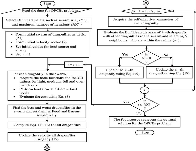
Figure 1 Flow chart of the PADFOM.
where
| (20) | ||
| (21) | ||
| (22) |
and are the random numbers is a constant
The DFO parameters such as and are usually tuned by a trial and error process to obtain the best solution. These parameters can be automatically tuned by an adaptive mechanism by treating them as additional variables and including them in the representation of dragonfly as
| (23) |
A swarm of dragonflies is initially formed and the cost function of each dragonfly is evaluated. The processes representing exploitation and exploration by Equations (11)–(15) are performed and the positions are adjusted by Equations (16)–(17) for each member in the swarm with a goal of lowering the cost. This process represents one iteration and this process is repeated till convergence. The proposed adaptive DFO based method (PADFOM) is well explained in Figure 1.
The optimal solution attained by the above solution process indicates the optimal node locations and number of CBs required for different load levels. The CBs can be spitted into fixed and switched type by the following mechanism.
• (1), obtained by Equation (9) is considered as fixed capacitor.
• for other load levels are considered as switched capacitors.
4 Simulation
The PADFOM has been applied on 33 and 69-node DNs, whose data are available in [18] and [19]. The procedure outlined in [20] has been engaged for performing the power flow, which is required for evaluating the cost function. The available minimum rating of CBs has been chosen as 150 kVAR. The load factors of 0.5, 0.8, 1.0 and 1.1 are multiplied with base-load powers to get different load levels of low, medium, full and excessive load scenarios respectively. The PADFOM has been obtained by setting the number of node locations for CB placement as 2 and then increased up to 6 for both systems, and found that the performances are satisfactory with compensation at 2 and 3 node locations for 33 and 69 nodes systems respectively.
Table 1 Number of CBs required for 33 node system
| Load Level | Node-6 | Node-8 |
| Low | — | — |
| Medium | 3 | — |
| Full | 8 | 1 |
| Excessive | 9 | 2 |
Table 2 Type of CBs required for 33 node system
| Node Nos. | Fixed CBs | Switched CBs |
| 6 | — | 150 kVAr * 9 nos. |
| 8 | — | 150 kVAr * 2 nos. |
33 Node Test System
The optimal locations and the number of CBs required for four distinct loading levels are given in Table 1. At low load level, there is no requirement for any compensation, while in medium load, three CBs are required at node-6. In case of full load and excessive load, compensation at nodes-6 and -8 are required as indicated in Table 1. As there is no need for reactive power compensation at low load level, the system does not require any fixed type of CBs, but it requires 9 and 2 numbers of switched type of CBs at node-6 and -8 respectively as furnished in Table 2. The performances in terms of the lowest VSI index observed in the network, the lowest VM observed in the network and the network real power loss before and after compensation by CBs are given in Table 3. It can be noticed that there is significant improvement in VS and VP and notable reduction in network loss.
Table 3 Performance for 33 node system
| Low | Medium | Full | Excessive | ||
| Before | 0.964 | 0.941 | 0.926 | 0.917 | |
| placing | 0.954 | 0.924 | 0.904 | 0.893 | |
| CBs | Loss (kW) | 48.78 | 130.71 | 210.97 | 259.64 |
| After | 0.979 | 0.963 | 0.952 | 0.947 | |
| placing | 0.967 | 0.937 | 0.921 | 0.916 | |
| CB | Loss (kW) | 38.01 | 101.89 | 163.32 | 197.21 |
Table 4 Number of CBs required for 69 node system
| Load Level | Node-54 | Node-57 | Node-58 |
| Low | 1 | 2 | — |
| Medium | 2 | 4 | — |
| Full | 4 | 4 | 7 |
| Excessive | 4 | 5 | 9 |
Table 5 Type of CBs required for 69 node system
| Node Nos. | Fixed CBs | Switched CBs |
| 54 | 150 kVAr * 1 no. | 150 kVAr * 3 nos. |
| 57 | 150 kVAr * 2 nos. | 150 kVAr * 3 nos. |
| 58 | — | 150 kVAr * 9 nos. |
69 Node System
The optimal locations and the number of CBs required for four distinct loading levels are given in Table 4. At all load levels, there is a need for reactive power compensation at nodes 54, 57 and 58. As this system requires compensation even at low load level, a fixed CB at node-54 and two fixed CBs at node-57 are required as indicated in Table 5. It also requires 3, 3 and 9 switched CBs at nodes-54, -57 and -58 to meet medium, full and excessive load levels respectively. The performances in terms of the lowest VSI index seen in the network , the lowest VM seen in the network and the network real power loss before and after compensation by CBs are given in Table 6. It can be seen that there is significant enhancement in VS and VP and notable reduction in network loss.
Table 6 Performance for 69 node system
| Low | Medium | Full | Excessive | ||
| Before | 0.942 | 0.903 | 0.874 | 0.859 | |
| placing | 0.942 | 0.903 | 0.875 | 0.861 | |
| CBs | Loss (kW) | 70.20 | 192.88 | 317.73 | 395.50 |
| After | 0.968 | 0.932 | 0.927 | 0.914 | |
| placing | 0.960 | 0.926 | 0.910 | 0.905 | |
| CBs | Loss (kW) | 64.17 | 143.591 | 247.936 | 319.10 |
5 Conclusion
Dragonfly Optimization (DFO) is a swarm based method, built from the inspiration of the static and dynamic swarming activities of dragonflies. The PADFOM employs the DFO in solving the OPCBs problem. The node locations and number of CBs to be placed at the chosen nodes are considered as problem variables and the enhancement of VS is considered as problem objective. The method has been featured by an adaptive mechanism that attempts to enhance the convergence and land at global best solution quickly. The simulation results on two standard DNs clearly exhibits the superiority in terms of improvement in VP, enhancement in VS and reduction in network loss.
References
[1] R. B. Prada, L. J. Souza, ‘Voltage stability and thermal limit: constraints on the maximum loading of electrical energy distribution feeders’, IEE Proc. Gen. Trans and Dist., Vol. 145, No. 5, pp. 573–77, 1998.
[2] M. Chakravorty, D. Das, ‘Voltage stability analysis of radial distribution networks’, International Journal of Electrical Power and Energy Systems, Vol. 23, No. 2, pp. 129–135, 2001.
[3] M. H. Haque, ‘A linear voltage stability margin for radial distribution systems’, Proceedings of IEEE PES General Meeting, Canada, pp. 1–6, 2006.
[4] J. C. Hernandez, ‘A Medina and F Jurado. Optimal allocation and sizing for profitability and voltage enhancement of PV systems on feeders’, Renewable Energy Journal, Vol. 32, No. 10, pp. 1768–1789, 2007.
[5] K. Prakash, M. Sydulu, ‘Particle swarm optimization based capacitor placement on radial distribution systems’, Proceedings of Power Engineering Society General Meeting, pp. 1–5, 2007.
[6] R. S. Rao, SVL. Narasimham, M. Ramalingaraju, ‘Optimal capacitor placement in a radial distribution system using plant growth simulation algorithm’, International Journal of Electrical Power and Energy Systems, Vol. 33, No. 5, pp. 1133–1139, 2011.
[7] A. R. Abul’Wafa, ‘Optimal capacitor placement for enhancing voltage stability in distribution systems using analytical algorithm and Fuzzy-Real Coded GA’, International Journal of Electrical Power and Energy Systems, Vol. 55, pp. 246–252, 2014.
[8] J. Vuletic, M. Todorovski, ‘Optimal capacitor placement in radial distribution systems using clustering based optimization’, International Journal of Electrical Power and Energy Systems, Vol. 62, pp. 229–236, 2014.
[9] S. Sultana, P.K. Roy, ‘Optimal capacitor placement in radial distribution systems using teaching learning-based optimization’, International Journal of Electrical Power and Energy Systems, Vol. 54, pp. 387–398, 2014.
[10] K.R. Devabalaji, K. Ravi, D. Kothari, ‘Optimal location and sizing of capacitor placement in radial distribution system using bacterial foraging optimization algorithm’, International Journal of Electrical Power and Energy Systems, Vol. 71, pp. 383–390, 2015.
[11] SK. Injeti, VK. Thunuguntla, M. Shareef, ‘Optimal allocation of capacitor banks in radial distribution systems for minimization of real power loss and maximization of network savings using bio-inspired optimization algorithms’, International Journal of Electrical Power and Energy Systems. Vol. 69, pp. 441–455, 2015.
[12] Y. M. Shuaib, M. S. Kalavathi, C C A. Rajan, ‘Optimal capacitor placement in radial distribution system using gravitational search algorithm’, International Journal of Electrical Power and Energy Systems, Vol. 64, pp. 384–397, 2015.
[13] A. Askarzadeh, ‘Capacitor placement in distribution systems for power loss reduction and voltage improvement: a new methodology’, IET Generation, Transmission and Distribution, Vol. 10, No. 14, pp. 3631–3638, 2016.
[14] K. S. Sambaiah, T. Jayabarathi, ‘Optimal Allocation of Renewable Distributed Generation and Capacitor Banks in Distribution Systems using Salp Swarm Algorithm’, International Journal of Renewable Energy Research, Vol. 9, No. 1, pp. 96–107, 2019.
[15] Seyedali Mirjalili, ‘Dragonfly algorithm: A new meta-heuristic optimization technique for solving single-objective, discrete and multi-objective problems’, Neural Comput and Applic. 2015.
[16] M. Hamdy, A.T. Nguyen, JLM. Hensen, ‘A performance comparison of multi-objective optimization algorithms for solving nearly-zero-energy-building design problems. Energy and Buildings, 2016.
[17] T. Dharmendra, P. Nikhil, R. Asha, S. Vijander, ‘Fractional Order PID (FOPID) Controller based Temperature Control of Bioreactor’, Proceedings of International Conference on Electrical, Electronics, and Optimization Techniques (ICEEOT), 2016.
[18] B. Venkatesh, R. Ranjan, ‘Optimal radial distribution system reconfiguration using fuzzy adaptation of evolutionary programming’, Journal of Electrical Power and Energy Systems, Vol. 25, No. 10, pp. 775–780, 2003.
[19] S. Sivanagaraju, N. Visali, V. Sankar, T. Ramana, ‘Enhancing voltage stability of radial distribution systems by network reconfiguration’, Electric power components and systems, Vol. 33, No. 5, pp. 539–50, 2004.
[20] P. Aravindhababu, S. Ganapathy, K. R. Nayar, ‘A novel technique for the analysis of radial distribution systems’, International Journal of Electrical Power and Energy Systems, Vol. 23, No. 3, pp. 167–171, 2001.
Biography

B. Suresh Babu received the B.E degree in Electrical and Electronics Engineering from Bharathiar University, Coimbatore, India in 1998, the M.E degree in Power Systems from Annamalai University, Chidambaram, India in 2001 and Ph.D degree from Anna University, Chennai, India in 2016. He is presently working as a Professor of Electrical and Electronics Engineering at Shri Vishnu of Engineering College for Women, Bhimavaram, Andhra Pradesh, India. He has 21 years of teaching experience since 1998. He is a life member of MISTE, MISEEE, MIE, MIAENG, MIEAE and MInSC. His research area includes power systems, FACTS devices, intelligent optimization algorithms.
Strategic Planning for Energy and the Environment, Vol. 40_1, 25–38.
doi: 10.13052/spee1048-5236.4012
© 2021 River Publishers