Research on the Intelligent Energy Governance of Parallel Hybrid Vehicle Based on Deep Learning
Feilong Wang
Department of Automotive Technology, XinXiang Vocational and Technical College, XinXiang 453000, China
E-mail: feilongwang666@xxvtc.edu.cn
Received 04 January 2022; Accepted 24 January 2022; Publication 02 April 2022
Abstract
To realize the intelligent energy governance of hybrid vehicles, a Deep-Q-Network energy controller based on the construction of parallel hybrid vehicle model is proposed, which aiming at energy loss problem of parallel hybrid vehicles and combining deep learning with reinforcement learning, and it is simulated through the ADVISOR software platform and compared with the traditional fuzzy logic strategy. The experimental results indicate that the DQN-based control strategy proposed in this paper reduces both the energy consumption and exhaust emissions of parallel hybrid vehicles. Compared with the traditional fuzzy control strategy, fuel consumption is reduced by 0.43L while the fuel economy increases by 10.9%. and exhaust gas such as CO, CO, NO the emission were reduced by 28.9%, 0.2%, and 7.4%, respectively. It shows the feasibility and effectiveness of the proposed methods.
Keywords: Parallel hybrid vehicle, energy controller, DQN.
1 Introduction
Electric vehicles were born with increasing fuel vehicle pollution, and more effective hybrid vehicles were proposed. In hybrid vehicle technology, energy governance is of great importance, and has strong impacts on the energy loss of hybrid vehicles. It is considered by the study that the energy governance is mainly to reasonably allocate the output torque of the engine and the motor according to the working condition information and working mode of the automobile, so as to effectively reduce the automobile fuel consumption and exhaust emissions, then to achieve the purpose of improving the energy utilization rate. Therefore, how to scientifically conduct scientific control of hybrid vehicle energy is significance to promote the popularization of electric vehicles. To solve the problem, Zhang Xudong, Wang Yachao, et al. proposes a bi-level energy governance strategy of plug-in hybrid electric vehicles with intelligent state-of-charge (SOC) reference for satisfactory fuel economy and battery lifetime based on fuzzy control theory [1–5]. In view of fuzzy control theory, a two-layer energy governance strategy for plug-in hybrid vehicles with smart state of charge (SOC) reference is proposed to obtain satisfactory fuel economy and battery life. The Q-learning algorithm is used to generate the SOC reference before departure by considering the nonlinearities and physical constraints of the model, while reducing the computational effort. At the bottom layer, a model predictive control (MPC) controller is designed to allocate system power flow online and track SOC reference values to improve fuel economy and extend battery life, using short-term drive speeds accurately predicted by radial basis function neural networks. In addition, the terminal SOC constraint is transformed into a soft constraint by a relaxation operation to ensure the feasibility of the solution and smooth tracking effect. Finally, the effectiveness of the strategy is verified by simulation, and the results suggest that the strategy provides significant improvements in fuel economy and battery life extension compared to the power consumption and power maintenance methods. More importantly, the robustness of the method is verified in the case of inaccurate unknown drive information, indicating that the method is well adapted for practical applications. Hyung-Joon Lee, Nguyo Huy et al. presented a proposed torque distribution strategy for parallel hybrid vehicles based on real-time optimization. Due to its high performance for hybrid electric vehicles, it is of interest to develop energy governance strategies. However, these methods are often complex and may require a large computational effort, which may hinder their application in real-world applications. The strategy is designed to minimize engine fuel consumption while ensuring battery charge retention through linear quadratic regulation in a closed-loop control scheme. Moreover, by reformulating the problem, the obtained strategy does not require the information of the engine efficiency diagram as in previous works in the literature. The obtained strategy is simple and straightforward, so it is easy to implement on a real-time platform. The method was evaluated by simulation using dynamic planning as a benchmark. Meanwhile, the real-time performance of the strategy is verified through power hardware-in-the-loop simulation experiments [6–10]. Alice Guille des Buttes et al. proposed that in order to optimize ignition, the thermodynamics of the three-way catalyst should be considered [11–15]. Based on this, this paper combines the research results of the above scholars, and puts forward the energy intelligent management research on parallel hybrid vehicles based on deep learning, to reduce the energy loss of hybrid electric vehicles and improve the energy utilization rate through energy controller design and system modeling.
2 Basic Principle of DQN Algorithm
Intensive learning belongs to machine learning, and its main character is that there is no labels in the training process of deep learning, mostly use the rewards and punishments given by the environment to learn [4]. It is widely used in Weiqi competitions, robot control and driverless driving, etc.
In reinforcement learning, Q learning is a commonly used algorithm, its calculation mode is to establish the Q table to save the Q value of various actions, then select the largest Q value from multiple actions for output, while using the reward value r to update the parameters [5]. The specific update formula is:
| (1) |
In this equation, is a decay coefficient, , when value is closer to 1, it indicates that learning should focus on immediate reward [6]. is the learning rate, the calculation process of the learning is shown in Figure 1:
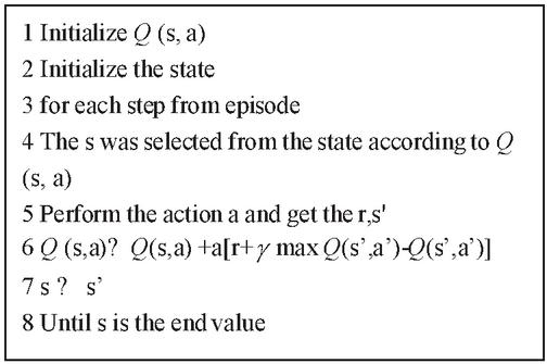
Figure 1 The computational procedure for learning.
In practical applications, the table can not store too many movements because of too large action ranges. Therefore, based on the basic principles of deep learning in this paper, adds the neural network to replace the Q table and obtains the output function through the neural network output, [7]. Thus, the (Deep-Q-Network, ), the characteristic of this algorithm is to set labels according to the updated method of . Removing redundant data in training through empirical replay, and ultimately to set the prediction and target, so as to improve the algorithm stability [8].
combined with the update mode, resulted the error function is as follow:
| (2) |
The target expression is as follow:
| (3) |
by setting the experience pool, transferring the stored data to the experience pool during learning, and then keeps updating it, so that the relevance of the data can be broken through, thus improving learning efficiency and training speed [9].
3 The DQN-based Energy Controller Design
3.1 Overall Strategy of Energy Consumption Optimization
The working condition data of hybrid vehicles is very complex with too large action rage. It is known that the Q table cannot store too much data information. Therefore, this paper combines deep and reinforcement learning for energy controller design for hybrid vehicles via Deep-Q-Network, .
Hybrid electric vehicle energy governance strategy based on is shown in Figure 2. It can be seen that, in the absence of any rules, its energy governance strategy is input from the initial state to the network, screened through the greedy algorithm, optimized control after independent learning, and the actions are finally output [10, 11].
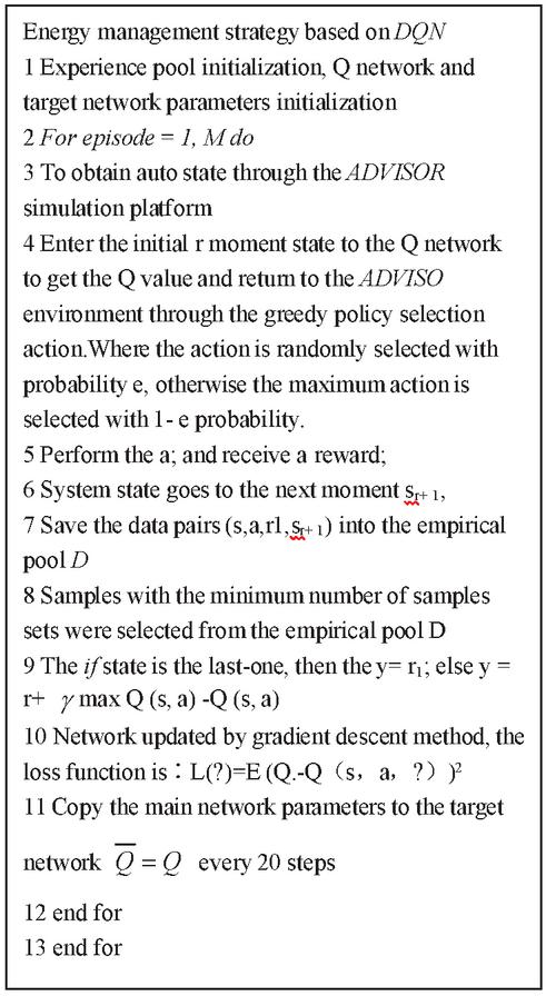
Figure 2 DQN-based energy governance strategy of power-mitigation vehicles.
3.2 Q-network Design
In DQN, Q-network has a greater impact on DQN control. the structure of DQN network is as follows.
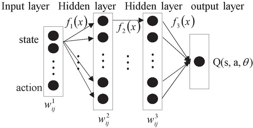
Figure 3 DQN network structure.
The network structure mainly consists of input layer, hidden layer and output layer, with the input objects being states and actions. The states are divided into torque difference and battery charge states. The hidden layer is mainly divided into two layers, which include 20 and 50 nodes, respectively. The node weights in this network structure are denoted as , where denotes the number of weight nodes; The depth of the layer is to . The excitation functions for the hidden and output layers are , and . The DQN network output can be expressed as , and the weight expression is:
| (4) | ||
| (5) | ||
| (6) |
By using the above equations, it can be calculated that:
| (7) | ||
| (8) |
3.3 Greedy Policy
In reinforcement learning, optimal control requires achieving the maximum of the cumulative reward, i.e., . While achieving the maximum cumulative reward, it is also necessary to fully meet the requirements of economy and avoid the local optimum of the obtained values. To solve this problem, is proposed to be adjusted by selecting a certain action arbitrarily by the probability of and selecting the best action to be operated by the probability of . This method can be used to solve the local optimum problem in reinforcement learning well, so as to maximize the use of various information. The greedy policy expression is:
| (9) |
3.4 Selection of Reward Function
To enhance the effectiveness of the DQN control strategy, suitable reward functions are selected for the control of engine and motor torque. Taking the torque difference and the state of charge as the state, it can be expressed as , . Taking the engine output torque as an action, it can be expressed as . The output torque is discretized and divided into 40 subsections, which can be expressed as:
| (10) |
The motor torque is obtained by subtracting the total motor demand torque from the engine torque, and it is intentionally normalized to improve the training speed and accuracy of the network. The normalization equation is:
| (11) |
The ultimate goal of the energy management system is to achieve energy savings and reduce fuel consumption. Therefore, the SOC value and the instantaneous fuel consumption of the engine are used as the excitation function, which results in the expression of the reward function as:
| (12) |
In the above equation, represents the instantaneous reward; is the instantaneous fuel consumption of the engine; and are the maximum instantaneous fuel consumption and the minimum non-zero instantaneous fuel consumption, respectively.
Generally speaking, the battery range can be controlled in the range of 0.40.7 by the reward function, thus effectively preventing the phenomenon of over charging and discharging to further save the amount of fuel consumption.
The loss function is then the variance of the error between the Q estimate and the Q reality, and the expression is:
| (13) |
Where, denotes the output of the parameter; , , is the target Q-value network. By constructing a loss function for a Q-network slower than the current network, the stability of the algorithm can be improved.
3.5 Experience Replay
To achieve global optimum, experience replay is set so that the control policy can be updated. Specifically, 50 sets of historical data are first selected to be placed in the experience pool and used as historical data;Then x is preserved in the experience pool, and the smallest data from it is arbitrarily selected to update the action, thus improving the randomness of action selection and achieving global optimum.
The experience pool data are selected from the ADVISOR platform, where the minimum number of samples in DQN is set to 40, the total number of experience pool samples is set to 1000, the discount factor is set to 0.99, and the learning rate is set to 0.9, and the minimum is taken to be 0.2.
4 Simulation Test
4.1 Modeling of Parallel Hybrid Vehicle Systems
To better test, in view of the characteristics of the hybrid vehicle system, this paper try to structure models of the engine, the motor, the battery, the wheels, the main reducer, the vehicle dynamics, the transmission and the whole vehicle.
4.1.1 Engine model
In the vehicle drive, the engine is the most critical driving force. The basic principle is to burn gasoline or diesel fuel to release energy to turn the crankshaft, from chemical to mechanical energy, so to boost the car driving force. Because the complexity of hybrid system, the engine has nonlinear characteristics. Therefore, this paper combines experimental knowledge and theoretical knowledge, scientifically and reasonably selects input and output data, simplifies the calculation while modeling and divides the model into four modules: torque calculation, speed estimation, fuel consumption and emission calculation. The specific model is shown in Figure 4.
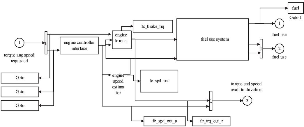
Figure 4 Engine model.
4.1.2 Motor model
Motor model, belongs to the second power source in hybrid vehicles, motor operation mainly switches between the engine and generator, the system choose the energy according to how the car runs. When the car torque is large, the motor can convert electric energy into mechanical energy, when the car brake, the motor can convert the remaining mechanical energy back to electric energy, so as to charge the battery [12]. The model can obtain the torque of inertia using the speed signal, thereby obtaining input torque and output power by meter checking. The generator model is mainly divided into three modules, namely the actual output torque of, the speed calculation module and temperature calculation module [13].
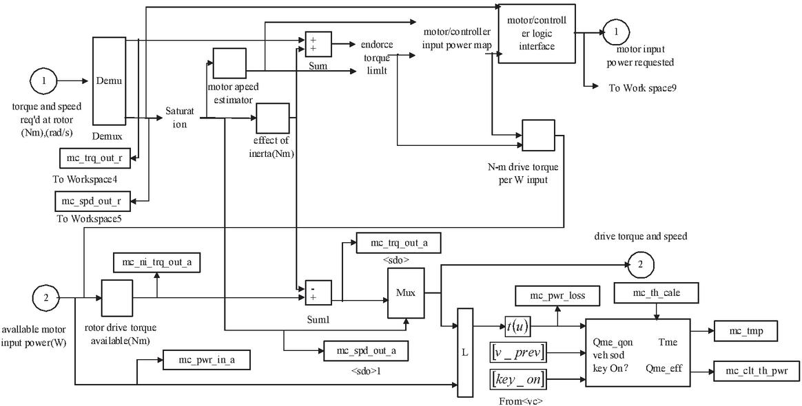
Figure 5 Motor simulation model.
4.1.3 Battery model
In the hybrid vehicle system, the battery is the most basic electric energy storage device. The model is easily susceptible to temperature in the process of charging or power generation, and it is an electrochemical process. At the same time, the model is affected by multiple factors during working, which is a non-linear process [14].
This paper based on the characteristics of the parallel hybrid vehicle system, adopting to Rmt model improved and optimized by the lead-acid battery model, which can analog out many steps when running the system. Mainly includes five modules: open circuit voltage and internal resistance calculation module, power limit module, current calculation module, SOC estimation module and thermal model module.
4.1.4 Wheel model
This module mainly outputs the actual torque and rotational speed according to the main reducer to perform its movement state, thus obtaining the traction force and speed of the tire. During system modeling, focus should be placed on the effects of resistance, inertia and friction produced during motion. Finding out the torque and angular speed of the wheel demand through the impact of the tire in contact with the ground [15]. The formula is as (4):
| (14) |
The wheel angular speed formula according to the sliding rate is.
| (15) | ||
| (16) |
In this formula, represents the traction force of the front wheel; represents the braking force of the front wheel; the radius of the wheel; the sliding rate of the wheel; the limiting speed of the front wheel.
4.1.5 Main reducer model
In the parallel hybrid vehicle system, the main reducer model can intuitively see the speed reduction and torque increase only when the car is moving. Therefore, to model the main reducer mainly can start from these two aspects: friction torque loss and accelerated torque of inertia. Generally, the friction torque loss is set to a fixed value. In this study, the main reducing gear model is shown in Figure 6 below.
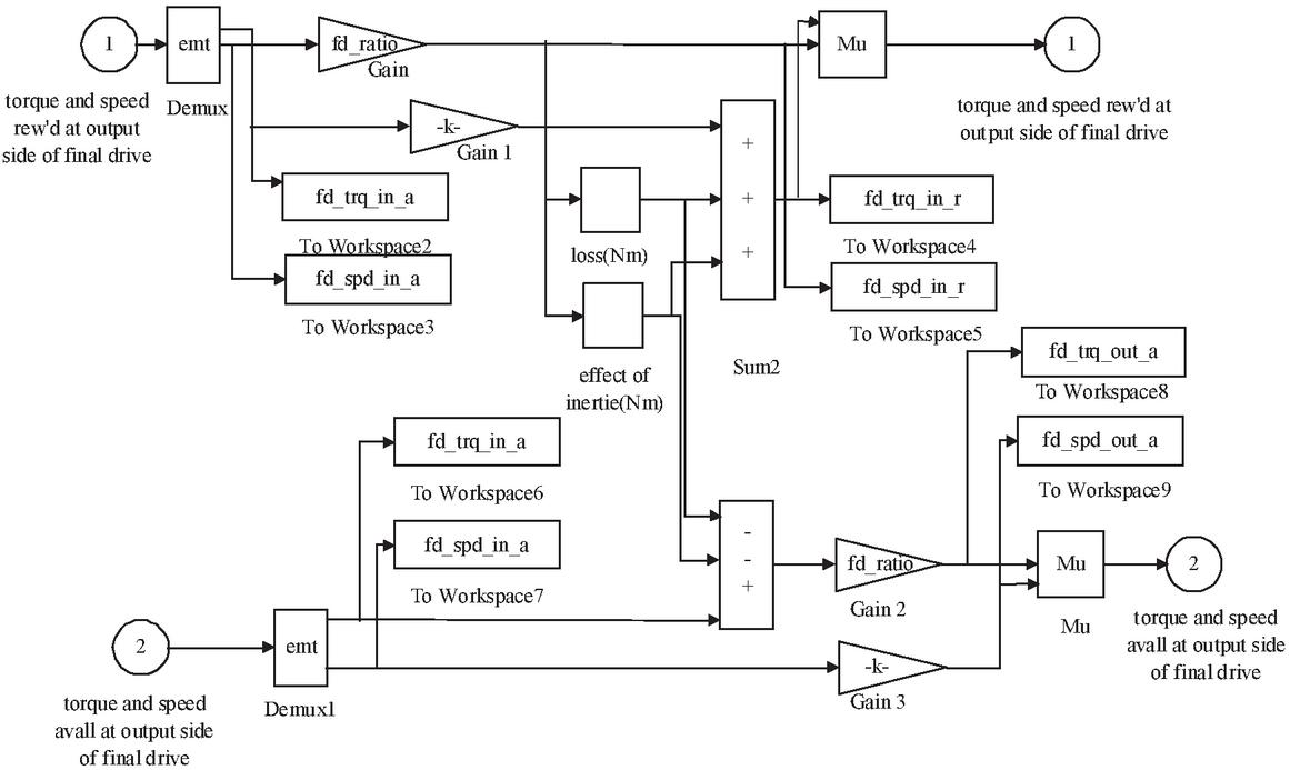
Figure 6 Simulation model of main reducing gear.
4.1.6 Vehicle kinetic model
This model is mainly solved by the force between wheel and ground friction. The iterative method is used to find out the acceleration of the vehicle. Meanwhile, considering the rolling, ramp and air resistance of the working state of the car, the vehicle speed should be calculated according to the integral step by step. Therefore, based on the above considerations, the whole vehicle model is designed as shown in Figure 7 below.
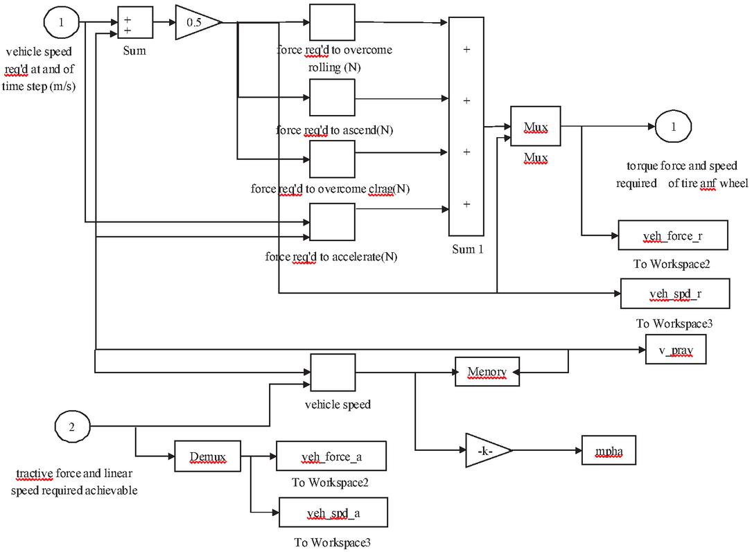
Figure 7 Simulation model of the whole vehicle dynamics.
4.1.7 Transmission model
Transmission is to transfer the rotational velocity and drive torque of the engine or motor according to each transmission ratio, so to achieve the purpose of deceleration and torque increasing. In ADVISOR software, the transmission model is generally located in the main reducer, generator and engine positions for power transmission. The main factors are the transmission ratio, inertia and friction loss, etc., which are modeled by the empirical formula.
First, the path is analyzed by the input torque and rotation speed signal, so that the torque and rotation speed are calculated as follows:
| (17) | ||
| (18) |
In this formula, represents the input torque of the main reducer; the transfer speed; the torque of mechanical friction loss; the torque of accelerated inertia.
4.1.8 Car model
After various sub-models of hybrid EVs are detailed, simulation experiments will be performed in the Matlab program and Simulink software. ADVISOR software is used to build the model structure is as follows. In the model, the arrow from left to right is the backward simulation path, which is the energy demand for each module in a specific cycle condition, and the arrow from right to left is the forward simulation path, that is, the actual energy output of each module.
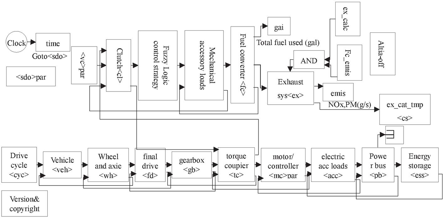
Figure 8 Vehicle simulation model.
4.2 Simulation Environment and Parameters
To verify whether the control strategy designed in this paper meets the driving requirements of most working conditions, the UDDS working condition map in urban roads developed by EPA is selected as the experimental parameters. The UDDS operating condition parameters are shown in Table 1.
Table 1 UDDS operating condition parameters
| Items | Parameters |
| duration(s) | 1369 |
| Driving distance(km) | 12.01 |
| Maximum speed(km/h) | 90.00 |
| Average speed(km/h) | 32.34 |
| Maximum acceleration(m/s) | 0.50 |
| Average acceleration(m/s) | 1.48 |
| Maximum speed reduction(m/s) | 1.48 |
| Average speed reduction(m/s) | 0.58 |
| Idle time(s) | 259.00 |
| Parking times | 17.00 |
Simulation parameters of parallel hybrid vehicles are shown in Table 2:
Table 2 Whole-vehicle simulation parameters
| Items | Parameters | Value |
| Vehicle | Quality of vehicle | 1.35t |
| Wind resistance coefficient | 0.335 | |
| Windward area | 2.0 | |
| Wheel radius | 0.282 | |
| Engine | Disposition | 1.0 |
| Maximum power | 41 | |
| Motor (permanent magnet synchronization) | Rated speed | 2000 |
| Maximum speed | 10000 | |
| Battery (lead-acid) | Discharge capacity | 25 |
| Block number | 25 | |
| Transmission (manual 5th gear) | Transmission ratio | 2.8413.45 |
In this paper, the control strategy is introduced to the automobile model of ADVISOR software for simulation experiments. Selecting the working diagram and specific parameters using UDDS, and the simulation results of fuzzy logic tactics are compared as follows:
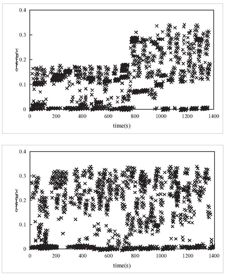
Figure 9 Engine efficiency comparison.
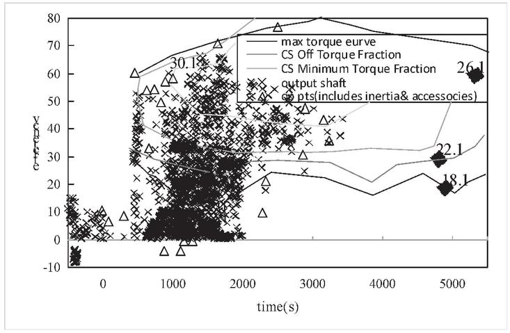
Figure 10 Engine map.
As can be seen from Figure 9, compared with the control strategy based on fuzzy logic, the control strategy engine proposed in this paper is mostly concentrated in the medium and high efficiency range, indicating that the engine proposing the control strategy has better efficiency. As can be seen from Figure 10, the engines are centrally distributed in the high efficiency range, thus reducing the energy consumption of parallel hybrid vehicles.
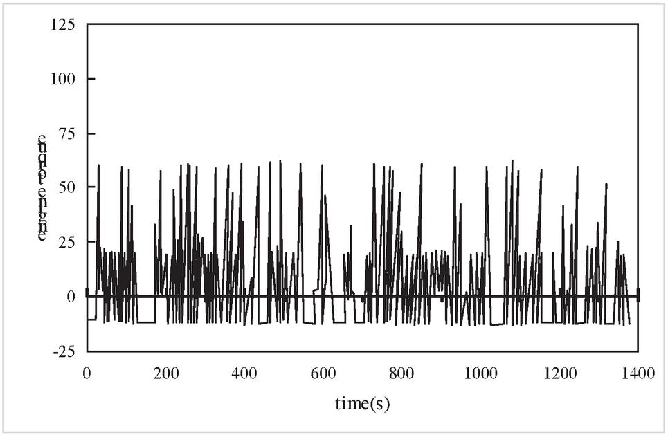
Figure 11 Engine and generator torque diagram.
Figure 11 is a torque diagram of the engine and generator, as driven by the combination of the engine and generator of a hybrid motor. From the comparison, the engine is off when the car just starts, and the generator provides all the demanded torque for the car; when the engine output torque is low, the generator delivers the remaining torque to the engine, from which the engine and the generator provide the demand torque together. Reducing the energy consumption can thus be achieved. The simulation comparison results of fuel consumption emissions based on hybrid vehicle energy goverance tactics and fuzzy logic control strategy are shown in Table 3.
Table 3 Comparison of the simulation results of fuel consumption and emission parameters
| Fuel Consumption and | Fuzzy Logic | A DNQ-based |
| Emission Parameters | Control Policy | Control Policy |
| Fuel consumption (L/100 km) | 3.91 | 3.48 |
| CH4 (g/km) | 0.197 | 0.140 |
| CO (g/km) | 1.283 | 1.280 |
| NO (g/km) | 0.256 | 0.237 |
According to the table above, the fuzzy logic control strategy fuel consumption is 3.91 L per 100 km. The DQN-based control strategy fuel consumption is 3.48 L per 100 km, 0.43 L less compared with the fuzzy control strategy. Fuel economy was improved by 10.9%. As for exhaust gas emission, HC is 0.197 km, CO is 1.283 km, NOx is 0.256 km, in the fuzzy logic control strategy. But in the control strategy of this paper, CH, CO and NOx are 0.140 km, 1.280 km, 0.237 km, reducing 0.057, 0.003 and 0.019, respectively compared with fuzzy logic control strategy. To sum up, based on DNQ control strategy to contrast the fuzzy logic control strategy, the automobile fuel economy is improved and the automobile exhaust emissions are reduced. The balance of battery charging and power generation is realized to meet the expected effect of this paper.
5 Conclusion
It is found by the study that the proposed control strategy based on DQN can reduce the energy loss of parallel hybrid vehicles effectively, and improve the vehicle fuel economy greatly. Meanwhile, the simulation experiment results indicate that compared with the fuzzy logic control strategy, the proposed engine based on the DQN control strategy is mainly concentrated in the high efficiency control field., indicating that it is more efficient. Combining the engine and the generator can reduce energy consumption of the hybrid car. However, due to condition limitations, this study is mainly manifested in the simulation experimental method, which is too idealized and impossible to simulate automobile conditions in real situations. Therefore, in a subsequent study, control strategy will be applied to real life to do experiments through real environment and real vehicles to achieve better experimental results.
References
[1] Zhang Xudong, Guo Lingxiong, Guo Ningyuan, Zou Yuan, Du Guodong, ‘Bi-level energy management of Plug-in Hybrid Electric Vehicles for Fuel Economy and Battery Lifetime with Intelligent State-of-charge Reference’, Journal of Power Sources, 2021, 481.
[2] Wang Yachao, Wang Junfang, Hao Chunxiao et al., ‘Characteristics of instantaneous particle number (PN) emissions from hybrid electric vehicles under the real-world driving conditions’, Fuel, 2021, 286(P2).
[3] Liu Teng, Tan Wenhao, Tang Xiaolin et al., ‘Driving conditions-driven energy management energy management strategies for hybrid electric vehicles: A review’, Renewable and Sustainable Energy Reviews, 2021, 151.
[4] He Hongwen, Wang Yunlong, Han Ruoyan et al., ‘An improved MPC-based energy mamnagement strategy for hybrid vehicles using V2V and V2I communications’, Energy, 2021, 225.
[5] Wang Yachao, Wang Junfang, Hao Chunxiao et al., ‘Characteristics of instantaneous particle number (PN) emissions from hybrid electric vehicles under the real-world driving conditions’, Fuel, 2021, 286(P2).
[6] De Nunzio Giovanni, Ben Gharbia Ibtihel, ‘Sciarretta Antonio A general constrained optimization framework for the eco-routing problem: Comparison and analysis of solution strategies for hybrid electric vehicles’, Transportation Research Part C, 2021, 123.
[7] Lee Hyung Joon, Shim Jae Kyung, ‘Multi-objective optimization of a dual mass flywheel with centrifugal pendulum vibration absorbers in a single-shaft parallel hybrid electric vehicle powertrain for torsional vibration reduction’, Mechanical Systems and Signal Processing, 2022, 163.
[8] Nguyn BåoHuy, Trovão João Pedro F., German Ronan, et al., ‘Real-Time energy management of Parallel Hybrid Electric Vehicles Using Linear Quadratic Regulation’, Energies, 2020, 13(21).
[9] Zhou Quan, Du Changqing, ‘A two-term energy management strategy of hybrid electric vehicles for power distribution and gear selection with intelligent state-of-charge reference’, Journal of Energy Storage, 2021, 42.
[10] Nazari-Heris Morteza, Mirzaei Mohammad Amin, Asadi Somayeh, Mohammadi-Ivatloo Behnam, et al., ‘A hybrid robust-stochastic optimization framework for optimal energy management of electric vehicles parking lots’, Sustainable Energy Technologies and Assessments, 2021, 47.
[11] Hao Lei, Wang Ying, Bai Yuanqi, Zhou Qiongyang, ‘Energy management strategy on a parallel mild hybrid electric vehicle based on breadth first search algorithm’, Energy Conversion and Management, 2021, 243.
[12] Li Weihan, Cui Han, Nemeth Thomas, et al., ‘Cloud-based health-conscious energy management of hybrid battery systems in electric vehicles with deep reinforcement learning’, Applied Energy, 2021, 293.
[13] Liu Yonggang, Li Jie, Gao Jun, et al., ‘Prediction of vehicle driving conditions with incorporation of stochastic forecasting and machine learning and a case study in energy management of plug-in hybrid electric vehicles’, Mechanical Systems and Signal Processing, 2021, 158.
[14] Nguyn BåoHuy, Trovão João Pedro F., German Ronan, et al., ‘Real-Time energy management of Parallel Hybrid Electric Vehicles Using Linear Quadratic Regulation’, Energies, 2020, 13(21).
[15] Benmouna A. et al., ‘Efficient experimental energy management operating for FC/battery/SC vehicles via hybrid Artificial Neural Networks-Passivity Based Control’, Renewable Energy, 2021, 178: 1291–1302.
[16] Elmouatamid Abdellatif et al., ‘Review of Control and Energy Management Approaches in Micro-Grid Systems’, Energies, 2020, 14(1): 168–168.
[17] Yi Huo and Fengjun Yan and Daiwei Feng, ‘A hybrid electric vehicle energy optimization strategy by using fueling control in diesel engines’, Proceedings of the Institution of Mechanical Engineers, Part D: Journal of Automobile Engineering, 2019, 233(3): 517–530.
[18] Felipe Jiménez and Wilmar Cabrera-Montiel, ‘System for Road Vehicle Energy Optimization Using Real Time Road and Traffic Information’, Energies, 2014, 7(6): 3576–3598.
[19] Hemmati S. et al., ‘Integrated cabin heating and powertrain thermal energy management for a connected hybrid electric vehicle’, Applied Energy, 2020: 116353.
[20] Xiong Rui et al. Joint Connection Modes, Uplink Paths and Computational Tasks Assignment for Unmanned Mining Vehicles’ Energy Saving in Mobile Edge Computing Networks’, IEEE Access, 2020, 8: 142076–142085.
[21] Aljohani Tawfiq M. and Ebrahim Ahmed and Mohammed Osama, ‘Real-Time metadata-driven routing optimization for electric vehicle energy consumption minimization using deep reinforcement learning and Markov chain model’, Electric Power Systems Research, 2020: 106962.
[22] Fotouhi Abbas et al., ‘Electric vehicle energy consumption estimation for a fleet management system’, International Journal of Sustainable Transportation, 2020, 15(1): 40–54.
[23] Ming Li et al., ‘Effect of pipes in heat pump system on electric vehicle energy saving [J]. International Journal of Green Energy, 2020, 17(11): 666–675.
[24] Luis F. Quirama et al., ‘Driving cycles that reproduce driving patterns, energy consumptions and tailpipe emissions’, Transportation Research Part D, 2020, 82(C): 102294–102294.
[25] Holden Jacob and Reinicke Nicholas and Cappellucci Jeff, ‘RouteE: A Vehicle Energy Consumption Prediction Engine’, SAE International Journal of Advances and Current Practices in Mobility, 2020, 2(5): 2760–2767.
[26] Naser Sina and Mohammad Reza Hairi Yazdi and Vahid Esfahanian, ‘A novel method to improve vehicle energy efficiency: Minimization of tire power loss’, Proceedings of the Institution of Mechanical Engineers, Part D: Journal of Automobile Engineering, 2020, 234(4): 1153–1166.
[27] I. K. Andronchev et al., ‘The Energy Performance Efficiency of Locomotives’, Russian Electrical Engineering, 2020, 91(3): 175–178.
[28] Sandeep V. et al., ‘Modeling of battery pack sizing for electric vehicles’, International Journal of Power Electronics and Drive Systems, 2020, 11(4): 1987–1994.
[29] A.L. Coiret et al., ‘Management of road speed sectioning to lower vehicle energy consumption’, Transportation Research Procedia, 2020, 45(C): 724–731.
Biography

Feilong Wang was born in HeNan, China, in 1988. From 2008 to 2012, he studied in HuangHuai University and received his bachelor’s degree in 2012. From 2012 to 2013, he worked in HeNan XinFei Special Purpose Vehicle Co.Ltd. From 2016 to 2019, he studied in BeiJing Institute of Technology and received his Master’s degree in 2019. Currently, he works in XinXiang Vocational and Technical College. He has published five papers. His research interests are included Vehicle engineering and Energy recovery.
Strategic Planning for Energy and the Environment, Vol. 41_2, 195–214.
doi: 10.13052/spee1048-5236.4124
© 2022 River Publishers