Research on Energy Consumption Model of Heat Pump Air Conditioning System for New Energy Vehicles Based on Digital Technology
Jingling Qin
College of Electromechanical and Automotive Engineering, Liuzhou City Vocational College, Liuzhou 545036, China
E-mail: qin_jingling@outlook.com
Received 09 June 2023; Accepted 01 August 2023; Publication 09 January 2024
Abstract
Energy shortages and environmental degradation are issues that are getting more and more significant globally. New energy vehicles are being promoted by the state due to the advantages of low pollution and low fuel consumption. However, due to battery technology, the range of new energy vehicles cannot meet the needs of users. As the most energy-efficient auxiliary device, the energy consumption of air conditioning will significantly reduce the range of new energy vehicles. In low temperature environments, heating energy consumption will reduce the range of vehicles by more than 50%. Therefore, the research aims to reduce the energy consumption of air conditioning systems in new energy vehicles by reducing load demand and improving operating efficiency. The study designs a low-temperature heat pump air conditioning system based on digital technology and then uses a computational algorithm to construct an energy consumption model for the heat pump air conditioning system of a new energy vehicle. According to the test results, the system’s average increase in heat production after activating the enthalpy charge is 35% and its average COP is 0.14% lower than when switched off. At 5C, the air outlet temperature of the system reaches up to 50.0C. Summer cooling energy consumption increases exponentially with temperature, while winter heating energy consumption decreases linearly with temperature. In addition, the range decreases significantly as the ambient temperature deviates from the human comfort zone. The decline in the winter range is more severe than that in summer, moreover, the range of modern energy vehicles is reduced by 30% at an average winter temperature of 10C. In summary, the low-temperature heat pump system offers greater performance. It is more useful in real-world applications and can offer a rational alternative to air conditioning’s energy-saving tactics.
Keywords: Heat pump, air conditioning, new energy vehicles, enthalpy compensation, digital technology.
1 Introduction
With the country’s economic and technological progress, new energy vehicles are becoming more and more popular, and car ownership in various countries has grown very rapidly [1]. However, the world’s energy demand is increasing, and China’s oil production capacity is severely limited, so reducing the fuel consumption and energy consumption of automobiles, as well as energy conservation, is now a top priority [2]. New energy vehicles can power cars by using electricity stored in batteries, offering the advantages of low fuel consumption, low emissions and low price [3]. However, the disadvantages of new energy vehicles are also obvious, as their range is extremely short and their charging time is very long [4]. The air conditioning equipment, which consumes a significant amount of energy, has a significant impact on the range; thus, maximizing new energy vehicle air conditioning performance and minimizing energy consumption during air conditioning heating are critical [5]. Relevant research in this field mainly constructs the air-conditioning load system of new energy vehicles by determining the heat load under various working conditions. On this basis, the low temperature heat pump air conditioning system is designed and the heat pump air conditioning system model is constructed based on digital technology. The research is unusual in that it is the first to propose a new calibration technique for the thermal load of new energy vehicles, and its accuracy meets current criteria. The research also introduces the different forms of make-up air heating system in the low-temperature heat pump air conditioning system, and finally proposes an energy consumption model for the heat pump air conditioning system of new energy vehicles.
2 Related Work
The energy required by the heating of modern energy vehicles in winter will greatly reduce their driving range. Reducing the energy consumption of air-conditioning heating is an effective way to improve the heating efficiency of vehicles. Therefore, the use of heat pump technology to improve the heating efficiency of automotive air conditioning has become a research focus of many scholars [6]. Yu et al. used a mixture of CO, R42. The results showed that in both heating and cooling modes, there was a considerable decrease in the system’s total operating pressure, gas cooler output temperature, high side pressure, and low side pressure [7]. Wang et al. studied a heating auxiliary equipment to help the ASHP in the external heat exchanger of the heat pump air conditioner (ASHP) frost to reduce the air conditioning capacity, which is a problem promoting the solution. According to the findings, this strategy increased the heating time by 17.9% and by 99.7% in frost-free and anti-frost modes, respectively, compared to the baseline mode [8]. Hussain used the refrigerant R1234yf instead of R134a to reduce ozone depletion leakage from refrigeration systems in air conditioners. The research results showed that the refrigerant was more effective in cooling the automobile air conditioning system (AACS) [9]. Bamisaye et al. used a 16-valve Nissan engine to explore how the air conditioning system input influences the engine’s temperature and speed while the vehicle is stationary. The findings revealed that the temperature jointly with engine speed do not change when the air conditioning system is activated [10]. Wang et al. improved the performance of the car air conditioning system, a cross-critical CO system model was created. The data showed how different refrigerant charge levels, as well as factors such as ambient temperature and compressor speed, affected the air conditioning system. The results can be used as a scientific and theoretical guide for system design and safety [11].
The function of car air conditioning is to guarantee the thermal comfort of passengers while ensuring a safe driving environment for the driver, so in addition to improving the cooling and heating efficiency, it can also reduce the energy consumption by reducing the load jointly with work of new energy vehicle air conditioning [12]. Tan Y et al. conducted an artificial study on the energy-saving performance of window accessories and analyzed the effect of window accessory parameters on the energy consumption of air conditioning in residential buildings in cities dominated by cooling and heating. The research results showed that solar transmittance and reflectance are the most influential factors on the energy-saving performance of window accessories [13]. Zhang J and others aim to effectively meet personal thermal comfort needs, achieve higher thermal comfort satisfaction, and reduce air conditioning energy consumption. By integrating thermal comfort experiments, residential simulation, user behaviour modelling and building energy consumption simulation technologies, the results show that the use of personal comfort systems in cold and hot conditions can significantly improve users’ thermal comfort and satisfaction [14]. Zhao et al. developed a simple algorithm. The results show that the algorithm can avoid high cost and reduce the energy consumption of 16.64% air conditioning to the minimum, and improve the overall energy efficiency of the air conditioning system in the whole process [15]. Zhang C et al. designed a simplified serrated guide vane leading edge considering the structural characteristics of bat wings and humpback whale pectoral fins. Numerical calculations showed that the new design can effectively reduce bending resistance in ventilation and air conditioning systems. Compared with conventional guide vanes, the maximum resistance of the new design can be reduced by 5%. Finally, full-scale experiments confirmed the drag reduction performance of serrated guide vanes [16]. Itoh T et al. found that liquid desiccant air conditioners can achieve sustainable living by reducing power consumption. Therefore, the study aimed to develop efficient dehumidification for liquid desiccant air conditioners. The dehumidification ability of 21 ammonium salts was analyzed, and the results showed that the hygroscopicity of double cation quaternary ammonium bis (dimethyl or diethyl phosphate) varied with the two terminal cation parts connected to the double cation, The carbon chain length of the spacer group (chain) of (CH 2) 2(CH 2) 3(CH 2) 6 increases. This trend remains unchanged when the methyl substituent on the cation and phosphate anion is replaced by ethyl [17].
According to the aforementioned study, it is quite common to calculate and evaluate the energy consumption of a heat pump air conditioner, but neither an intelligent model nor a calculation of the heat load of an air conditioner has been studied. Meeting the energy consumption needs of new energy vehicles in modern society is therefore an important task. The aim of the experiment is to reduce the energy consumption of the air conditioning system of the new energy vehicle. The intelligent energy consumption model of the heat pump air conditioning system of the new energy vehicle is constructed in order to carefully study the elements that affect the energy consumption of the air conditioning system.
3 Building a Heat Pump Air Conditioning System Energy Consumption Model for New Energy Cars
3.1 Construction of New Energy Vehicle Air Conditioning Load System
Researchers are paying increasingly greater attention to the digitalization of information in modern society as a result of the advancement of information technology [18]. Digital technology is the technical basis of intelligent technology and information society, and also the technology needed to develop new energy vehicle digitalization [19]. The most crucial phase in developing the air conditioning system for new energy vehicles is determining the load, whose precision influences how well the air conditioning system works. Therefore, the research has created the air conditioning load system of new energy vehicles and laid a solid foundation for follow-up actions. New energy vehicle air conditioning load system (ACLS) can be built by different classification methods, as shown in Figure 1.
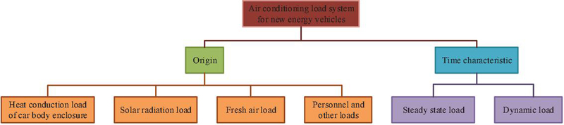
Figure 1 Construction of new energy vehicle ACLS.
Equation (1) illustrates the computation of the new energy vehicle’s steady-state load.
| (1) |
In Equation (1), is the total air conditioning load, is the fresh air load, is the heat transfer load of the vehicle envelope, is the solar radiation load, and is the personnel and other loads. The symbols in front of the loads are the direction of heat flow, with “” being heat flow into the cabin and “” being heat loss from the cabin. To achieve more accurate determination of Heat Transfer Load of Car Body Enclosure (HTLCBE) values under different operating conditions, the study uses CFD calculations and test operations to obtain a semi-empirical formula for HTLCBE as Equation (2).
| (2) |
In Equation (2), is the vehicle’s integrated heat transfer coefficient, is the difference between the vehicle’s interior temperature on average and the outside temperature, and are the external surface areas of the windows and the roof, respectively. Solar Radiation Heat Load (SRHL) is the main component of the air-conditioning load of new energy vehicles in summer. Under different solar radiation intensities, the outer surface temperature of the car body and the direct solar radiation heat load have been calibrated by the experiment, and the SRHL can be calculated as in Equation (3).
| (3) |
In Equation (3), is the ambient temperature heat load, is the difference between and ambient temperature, and is the typical interior cabin temperature. Equation (4) is used to determine the people load.
| (4) |
In Equation (4), is the number of people in the vehicle, is the metabolic heat production rate, is the surface area of the human body, and are the average weight and height of men, respectively. At present, the measurement of dynamic load requires a huge amount of experimental work and cost, so there is an urgent need for a dynamic load calibration method that can conveniently and cheaply calibrate the dynamic load of air conditioning under different working conditions. However, at present, there is no good method for calibrating the dynamic load required for preheating the body. A new method for handling dynamic load is proposed. Its basic premise is to use the vehicle air as the control body and to consider temperature changes caused by heat exchange between the air and other vehicle components as changes in the vehicle environment. The heat capacity of the air is taken into account while the dynamic load of the air conditioning system is handled, thus simplifying the control equation. The heat transfer in the vehicle is shown in Figure 2.
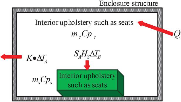
Figure 2 Diagram of heat transfer in vehicle.
Figure 2 demonstrates that the major sources of heat flow within a car are convective heat exchange with interior trim like seats and additional heat input from the outside, which happens via the car’s envelope between the air inside and outside. The meanings of each parameter are as follows: is the variation in temperature between the air within and the ambient temperature outside, is difference between the seat interior and the outside air temperature. and are the air’s mass and the interior of the car respectively; and are, respectively, a car’s interior and the air’s ability to hold heat; is the area of the interior of the car seat; is the rate of convective heat transfer between the air within the automobile and the surface of the car seat. According to the energy conservation equation, can be converted into the expression of , see Equation (5).
| (5) |
In Equation (5), is a constant. When the heater is on in the winter, the temperature of the interior of the car seat at the starting moment is the same as the ambient temperature , so the initial value of is 0, and can be obtained. Substituting into the energy conservation equation, can be got; If the air is taken inside the car as the control object, the air inside the car’s specific heat capacity can be considered as a function of time change, and get its expression. Calculate as Equation (6).
| (6) |
In Equation (6), is heat transfer term. In the above formula, tends to zero with time, which is smaller than , so it can be ignored where tends to 0 with time. Equation (7) can be obtained.
| (7) |
and are known values. Considering that the car is heated by a constant heat source and there is no other source of heat, is also known relative to time. The variation of and the total heat entering the car with respect to time is found. The relationship between and can then be established by taking a discrete pair of time for Equation (7) and , as shown in Equation (8).
| (8) |
From Equation (8), is a monotonically increasing term with time, and its value is always positive. At this point, there must be an inverse function of on time, and then it can be substituted into the expression of to find the function of on . Finally, use to calculate the variation of under other initial conditions.

Figure 3 Schematic diagram of three kinds of air replenishment and enthalpy increasing system schemes.
3.2 Building a Heat Pump Air Conditioning System Energy Consumption Model for New Energy Cars
The digital transformation has led to the endless emergence of new digital technologies and the rapid development of new energy vehicles. The air conditioning and heat dissipation systems in new energy vehicles need to use digital technologies to further improve the safety and comfort of the vehicles. In the winter heating conditions, the car’s range will be severely lowered by the heating load. As a result, selecting a heat pump heating and cooling system may significantly increase the heater’s energy efficiency. The configuration of the conventional heat pump system, which employs a four-way valve, is relatively basic. However, there is still a need for defogging in automobile air conditioners, so the traditional heat pump system cannot meet the needs of new energy vehicles. The research needs to further develop the low-temperature heat pump system to meet the functional requirements of the air conditioning system. The make-up enthalpy technology has been commonly used in domestic systems, and previous research results have verified its stability and reliability, which is one of the effective means to enhance the performance of heat pumps [20]. There are two forms of air replenishment and enthalpy enhancement in the research. Based on this, two types of air conditioning heat pump systems were designed, namely the condenser branch and the economizer branch. In addition, to investigate the effect of economizer capacity on the air conditioning heat pump system, improvements were made to the economizer branch, resulting in an air conditioning heat pump system that changes the economizer capacity. The specific air conditioning heat pump system diagram is shown in Figure 3.
Figure 3(a) is the most common form of the system, which is a down-flow unit. The make-up air is led out from the rear of the condenser, becomes two-phase after throttling, overheats in the economizer, and finally injects into the make-up air chamber of the compressor. Figure 3(b) is highly consistent with Figure 3(a), but the economizer capacity is increased and it is a counter-flow device. Figure 3(c) shows the charge gas enthalpy system of the air conditioning heat pump proposed in the study, which differs in that the branch point of the charge gas path is behind the economizer. In this case, the refrigerant subcooling in front of the charge gas control valve is greater, which is more conducive to the stable operation of the system compared with the original form. The capacity of the economizer is the same as that in Figure 3(b). The change of its layout makes the inlet enthalpy of the make-up air circuit lower, which can further increase the heat exchange of the economizer. In order to better evaluate the energy consumption of the designed low-temperature heat pump air conditioning system, a new energy vehicle air conditioning energy consumption model is studied and constructed. The influencing factors of air conditioning energy consumption in new energy vehicles are calculated from the input power and the operating time of the system, as shown in Equation (9).
| (9) |
in Equation (9) is the energy consumption value of the air conditioning system within one day; and respectively represent the input power of the cooling and heating time regulation systems of the air conditioning system; and respectively refer to the operating time of the air conditioning system in cooling and heating modes; is the different time of the day, from 0 to 23 o’clock. represents the time when the air conditioner is turned on at a certain time of the day, is the total length of driving all day, is the proportion of trips at different times, and is the proportion of people who are dissatisfied with the thermal comfort of the environment at different times. According to the analysis of Equation (11), it can be seen that the time of turning on the air conditioner is determined by the climate conditions, driving time and the proportion of trips, so these three factors are used as input conditions. The construction process of this air conditioning energy consumption model is shown in Figure 4.
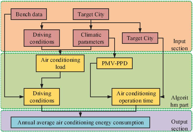
Figure 4 Heat pump air-conditioning system energy consumption model flow for new energy cars.
Figure 4 shows that the input part includes the test bench data, driving conditions in the target city, climate parameters and average daily driving hours. The algorithm part needs to test the input power and thermal comfort of the air conditioning system, and then determine the air conditioning opening time at different times in combination with the average daily driving time and travel time ratio. Finally, the energy consumption of the air conditioning system at different times can be determined and the typical annual energy consumption for air conditioning can be calculated. The air conditioning load of a car changes continuously with the speed of the car and the driving conditions can reflect the driving characteristics of a car in a region, so the New European Driving Cycle (NEDC) conditions were chosen for the study. The air conditioning energy consumption per unit time is calculated by the average energy consumption in one NEDC cycle condition, but there are differences in the average speed of different urban roads, and the speed of NEDC condition needs to be corrected, see Equation (10).
| (10) |
In Equation (10), and are the vehicle speeds in the -th second under the NEDC cycle conditions before and after the correction. is the city’s average speed for vehicles, and is the NEDC cycle’s average vehicle speed. The TMY2 climate database is used as the input of meteorological parameters in the model, and the monthly mean hourly dry-bulb temperature, relative humidity and solar radiation intensity are used to calculate the PMV-PPD value. Since air conditioning is used only when the car is driven, the driving time of the vehicle directly affects the air conditioning energy consumption. In addition, the driving time of different types of vehicles also varies, so the model selects two types of light vehicles, Private Car (PC) and Commercial Vehicles (CV). In general, the intensity of use of CV is higher than that of PC. The model considers that the hourly average driving time of CV is 1.3 times that of PC, and there is no significant difference between their average speed. From this, the average daily driving time of light vehicles in the model and the hourly travel ratio between 6–24 hours, which is the most in a day’s travel period, can be obtained, as shown in Formula (11).
| (11) |
In Equation (11), is the average daily driving time of PC, , are the number of registered PC and CV, respectively. and are the hour-by-hour travel ratios of weekdays and weekends, respectively. The model considers to be applicable to all cities. In the air conditioning system performance prediction, the change of evaporator inlet air volume and vehicle speed under fresh air mode needs to be corrected, and the relationship between the corrected fresh air volume into the vehicle body and vehicle speed is shown in Equation (12).
| (12) |
If the PMV of the new energy vehicle is greater than 0, it must also have a cooling requirement for defogging. The cooling system for defogging is usually at an ambient temperature of 0–10C, at which time the air conditioning operation time can be calculated by the relative humidity of the external environment as in Equation (3.2).
In Equation (3.2), is the proportion of the time of defogging and cooling to the total vehicle operation time, and RH is the relative humidity of the external environment. The real input power of the system in the cooling mode needs to be rectified in the air conditioning system input power algorithm. The PTC heater’s heating efficiency is 0.95 in the heating mode, and its input power can be calculated at . When the ambient temperature is very low, the heat pump system will start the PTC heater for auxiliary heating, and the heating input power of the entire air conditioning system can be calculated. In the defogging mode, the PTC heater also needs to include the heat of the defogging reheat, such that may be used to compute the system’s total input power. The relevant calculation is shown in Equation (14).
| (14) |
In Equation (14), is the input power of the system obtained by fitting the curve to the experimental data. and are the enthalpy of air in the use area and the experimental condition, respectively. is the heating load of the car, is the heat pump system’s input power. is the system’s efficiency ratio when it is cooling. The input power of the defogging mode for a heat pump system is regarded as being equivalent to that of the heat pump mode. Finally, the expression between PTC heater energy consumption and geographical location can be obtained. The expression between air conditioning energy consumption and relative range can also be obtained. As shown in formula (15):
| (15) |
In Equation (15), is the corrected latitude, is the correction factor of latitude with respect to altitude, and is the energy consumption of the car driving. The energy efficiency ratio calculation of the automotive heat pump system is shown in Equation (16).
| (16) |
In Equation (16), represents the heat absorbed by the evaporator from the environment, and represents the input power of the compressor.
4 Performance and Use of Heat Pump Air Conditioning System Energy Consumption Model for New Energy Cars
4.1 Performance Evaluation of a New Energy Vehicle’s Low-temperature Heat Pump Air Conditioning System
In order to verify the performance of the low-temperature heat pump air conditioning system of the new energy vehicle proposed in the study, the working conditions are determined according to the actual working requirements. The parameters of the system components are as follows: EVI compressor speed range is 1000–8500 rpm, micro-channel parallel flow heat exchanger is 660*500*16 (mm), two types of economizers are 12 and 26 pieces, the main expansion valve is EAS-14M07 electronic expansion valve, and the charge air enthalpy expansion valve is Shian 1.5RT. The results of the EVI test are displayed in Table 1.
| Working Condition No1 | 1 | 2 | 3 | 4 | 5 | 6 | 7 | 8 | 9 | 10 |
| Outdoor side temperature (C) | 18 | 18 | 12 | 12 | 0 | 7 | ||||
| Wind speed at outdoor side (m/s) | 4.5 | |||||||||
| Indoor temperature (C) | 18 | 7 | 12 | 2 | 0 | 7/6 | ||||
| Indoor air volume (m/h) | 400 | |||||||||
| Compressor speed (rpm) | 8500 | 4500 | 6500 | 8500 | 4500 | 6500 | 6500 | 8500 | 4500 | 4500 |
| Air make-up pressure level | EVI off/multiple make-up pressure levels | EVI on | ||||||||
Table 1 shows that owing to the broad working range of the new energy vehicle air conditioning system, the exterior side’s lowest temperature was adjusted at 18C in accordance with the low-temperature heat pump system’s design criteria. Other temperature points are chosen to examine the operational condition of the low-temperature heat pump system in different states and the evolution of the make-up gas enthalpy system over time. For the indoor ambient temperature, it has been avoided to set the inlet air temperature as the optimum temperature inside the car. In winter, the outdoor side temperature is very low, the air in the cabin is small, and the moisture emitted by the human body is easy to condense on the windshield surface, forming condensation fog, thus affecting driving safety. Therefore, two limit values (100% and 70%) of fresh air volume are used to ensure that the relative humidity in the vehicle is not too high when heating the air conditioner of new energy vehicles, so as to avoid the occurrence of windshield condensation. In the heating mode, the head-on wind speed on the outside of the system room has little effect on the west energy, so 4.5 m/s was selected. 4500, 6500 and 8500 rpm compressors were selected for testing to investigate the performance of different EVI speeds. To quickly raise the temperature in the vehicle, the maximum speed of the compressor is 8500 rpm. Among them, the heating capacity is the most concerned in the system performance. The research first selects the maximum heating capacity of the system after opening the air supply and enthalpy increase, and compares the performance of the system when closing the air supply and enthalpy increase, to evaluate the system characteristics as a whole, and to obtain the system efficiency ratio. The results are shown in Figure 5.

Figure 5 Comparison of the energy efficiency ratio and heating capacity when the heat pump air conditioning system is on and off.
Figure 5 shows that the heating capacity of the system has increased significantly by 11.2% – 95%, with an average increase of 35%. After closing the air supply and the enthalpy increase, the heating capacity of conditions 4 and 8 is lower than that of conditions 1 and 5. However, after opening the air supply and enthalpy boost, the heating capacity of the four working conditions is approximately the same, indicating that a high condensation pressure is more conducive to the performance of the air supply and enthalpy boost system. In addition, the inlet air temperature of cases 4 and 8 is higher than that of cases 1 and 5, and there is no big change in the heating capacity, which indicates that the system outlet air temperature of cases 4 and 8 is higher, and they are both low-temperature heat pump systems that are beneficial to new energy vehicles. In comparison to turning off EVI, the total change in COP after activating the charge air enthalpy is not appreciably different, ranging from 11.6% to 11.25, with an average drop of 0.14%. To sum up, the performance of the system after opening the air supplement and enthalpy increase has no obvious difference from that when closing, but it is far higher than the efficiency of the original PTC electric heater. Another advantage of the make-up enthalpy system is that it can significantly reduce the exhaust temperature of the EVI, so Figure 6 shows a comparison of the compressor exhaust temperature between the low-temperature heat pump system’s on and off states under normal operating circumstances.
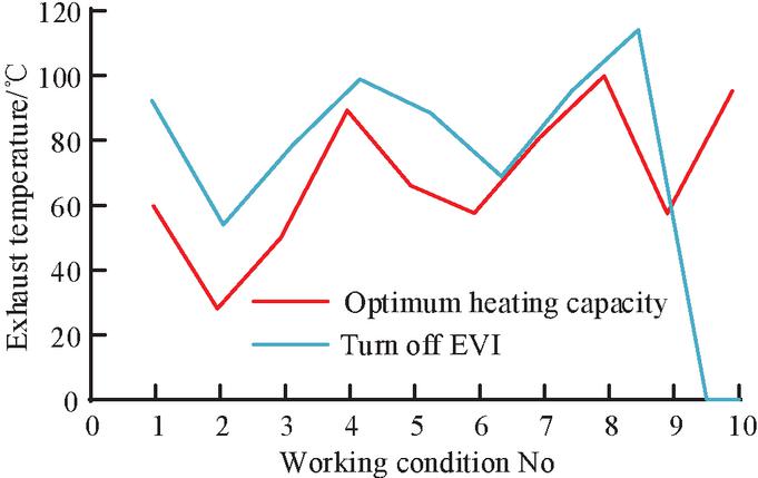
Figure 6 The compressor exhausts the heat pump air conditioning system’s temperature under typical working conditions when it is opened and closed to increase enthalpy.
Figure 6 shows that the exhaust temperature of the compressor is much lower when it is operating than when it is not. The highest exhaust temperature is 100.1C and the average decrease over the 8 operating conditions is 10.75%, demonstrating how much the air supplement and enthalpy increase can help the compressor work more efficiently. The investigation compared the temperature of the passenger compartment and the original vehicle PTC with the air outlet of the low-temperature heat pump system at various temperatures. The results are shown in Figure 7.
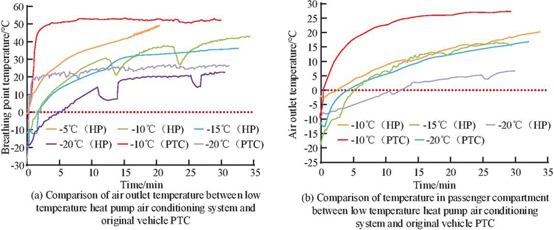
Figure 7 Comparison of the temperature of the passenger compartment and the low temperature heat pump air conditioning system from the original car PTC.
From Figure 7(a), the outlet temperature of the low-temperature heat pump system is similar to that of the original vehicle PTC at 20C. At 15C and 10C, the final outlet temperature of the system is 36.6C and 43.0C respectively. At 5C, the maximum outlet temperature of the system can reach 50.0C, which can fully meet the needs of human comfort. In addition, the heating time of the system is long. This problem can be solved by adding auxiliary PTC, and can also make up for the heat gap of the system under extreme conditions. Figure 7(b) shows that the average temperature of the passenger compartment and the original vehicle differ greatly, and the compressor stops working twice due to the instability of the compressor mass. At 10C, the average temperature in the car is 20C, which can maintain the comfort of the car environment. To scientifically validate the performance of the energy consumption model proposed for the new energy heat pump air conditioning system, comparative experiments were carried out using the air conditioning energy consumption models from references [11, 12] and [14].
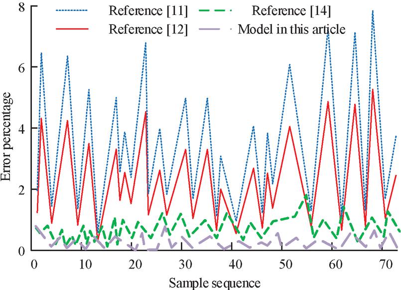
Figure 8 Comparison results of error percentages between different models.
The results of comparing the error percentages of the different air conditioning energy consumption models are shown in Figure 8. From Figure 8, the proposed air conditioning energy consumption model has the smallest error percentage, with an average error percentage of 1.25%. The model corresponding to reference [11] has the largest error percentage of 5.67%, followed by the error percentage value of reference [12] with 3.24%. The above results show that in the error comparison experiments of different models, the proposed energy consumption model for the heat pump air conditioning system of new energy vehicles has the highest accuracy and good precision.
4.2 Analysis of the Use of the Heat Pump Air conditioning System’s Energy Consumption Model in New Energy Vehicles
To explore the application of the energy consumption model of the heat pump air conditioning of the new energy vehicles in real life, the influencing factors of the annual energy consumption of the new energy vehicles are analyzed, and the influence of various influencing factors on the system energy consumption is quantified. The impact of climate conditions and geographical location on the energy consumption of the air-conditioning system of new energy vehicles can be obtained, and the results are shown in Figure 9.

Figure 9 The link between low-temperature heat pump air-conditioning system energy usage, temperature, and latitude for new energy vehicles.
Figure 9(a) shows how the energy used for cooling in the summer grows exponentially with temperature. This is because, after the temperature hits 25C, the heat pump system must raise the EVI speed to fulfill the evaporator’s output temperature requirements. Figure 9(b) demonstrates that the air conditioning energy consumption of heating in winter presents a linear decline trend with the increase of temperature, which is determined by the air conditioning load of new energy vehicles in winter. From 9(c), the temperature decreases linearly with the increase of altitude. After the latitude correction, the energy consumption of the heat pump system of the 100 km new energy vehicle increases linearly with the increase in latitude. According to the algorithm calculation and the impact of climate on the range, the impact of the heat pump air conditioning system of new energy vehicles on the range can be obtained as shown in Figure 10.
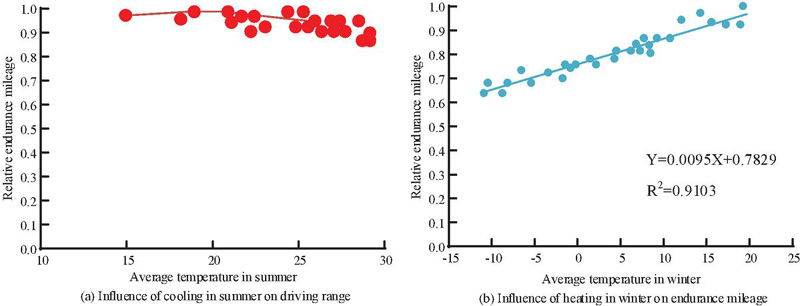
Figure 10 Influence of energy consumption of low temperature heat pump air-conditioning system on endurance mileage.
As can be seen from Figure 10, the range tends to decrease significantly as the ambient temperature deviates from the human comfort zone. The decline in winter range is more severe compared to summer. The range of new energy cars is reduced by 30% at 10C on average throughout the winter.
5 Conclusion
The development of new energy vehicles has been aided by suitable legislation in numerous nations, and they are now extensively employed in the actual world. However, the energy consumption of air conditioning of new energy vehicles will seriously affect the range, especially in winter. More digital methods may be employed to overcome the issue of energy consumption of air conditioners for new energy vehicles as science and technology advance. The low temperature heat pump air conditioning system is built by introducing the technology of adding air and boosting enthalpy after first studying and building a new energy vehicle air conditioning load system. The new energy vehicle heat pump air conditioning system’s energy consumption model is then constructed. The research results show that in the performance verification stage of the low-temperature heat pump air conditioning system, the average increase value of the system heating capacity after opening the air supply and enthalpy increase is 35%. The average COP is 0.14% lower than that of the closed one after opening the air supplement and increasing the enthalpy; The compressor exhaust temperature decreased by 10.75% on average. The energy consumption of cooling in the summer rises exponentially with temperature, while that of heating in the winter falls linearly with temperature in the application phase of the energy consumption model of the heat pump air conditioning system of new energy vehicles. As the ambient temperature deviates from the comfort zone of the human body, the range shows a significant downward trend. The drop in endurance mileage in winter is more serious than that in summer. At the average temperature of 10C in winter, the range of new energy vehicles will drop by 30%. In summary, the energy consumption model of the heat pump system proposed in the study has excellent effectiveness and applicability, and has optimized the low-temperature heating performance of the heat pump, providing a reference for the calculation and evaluation of annual energy consumption in the field of new energy vehicles. However, there are still shortcomings in the research, mainly including the following two points. Firstly, in existing models, the temperature inside the vehicle is characterized by the average temperature, which lacks temperature differences between different air masses; secondly, the influence of various body components on the air conditioning load is still relatively wide. With further research in the future, a database of the effects of body components on the air conditioning load can be established, which will make it easier to optimize the air conditioning load from the perspective of body materials in the future. In addition, research can refine the calculation of air mass temperature inside the car, and colleagues can further evaluate the impact of local air supply and other factors on air conditioning energy consumption.
References
[1] Han Q, Niu S, He L. Bifurcation and stability of resonance of electric vehicle powertrain: Focus on the influence of electromagnetic parameters. Proceedings of the Institution of Mechanical Engineers, Part D: Journal of Automobile Engineering, 2022, 236(8):1840–1848.
[2] Son D H, Bae M J, Cheong I W, Park Y I, Jin C K, Bae H E, Jeong J E, Lee S H. Fast, Localized, and Low-Energy Consumption Self-Healing of Automotive Clearcoats Using a Photothermal Effect Triggered by NIR Radiation. ACS Applied Polymer Materials, 2022, 4(5):3802–3810.
[3] Zhang Z, Liu Y, Wang J. Optimal Design of Multi-channel Water Cooled Radiator for Motor Controller of New Energy Vehicle. CES Transactions on Electrical Machines and Systems, 2022, 6(1):87–94.
[4] Xiong Y, Qin S. Differences in the effects of China’s new energy vehicle industry policies on market growth from the perspective of policy mix: Energy & Environment, 2021, 32(3):542–561.
[5] Wang S, Chen G, Huang D. Can the New Energy Vehicle Pilot Policy Achieve Green Innovation and Emission Reduction? Sustainability, 2021, 13(15):1–21.
[6] Yang C, Yang T, Chen P, Huang K. An Innovative Design of Regional Air Conditioning to Increase Automobile Cabin Energy Efficiency. Energies, 2019, 12(12):1–16.
[7] Yu B, Yang J, Wang D, Shi J, Guo Z, Chen J. Experimental energetic analysis of CO2/R41 blends in automobile air 17 conditioning and heat pump systems. Applied Energy, 2019, 239(APR.1):1142–1153.
[8] Wang F, Zhao R, Xu W, Huang D, Qu Z. A Heater-Assisted Air Source Heat Pump Air Conditioner to Improve Thermal Comfort with Frost-Retarded Heating and Heat-Uninterrupted Defrosting. Energies, 2021, 14(9):1–13.
[9] Hussain R, Ali I. The Experimental Assessment of R134a and Its Lower GWP Alternative R1234yf in an Automobile Air Conditioning System. university of Baghdad Engineering Journal, 2019, 25(12):1–14.
[10] Bamisaye O, Oyerinde A, Essien U. Investigation of the Effects of Air-Conditioning System on the Temperature and Speed of Automobile Engine Using Paired T-Test and Regression Analysis. Open Access Library Journal, 2019, 06(1):1–14.
[11] Wang A, Yin X, Fang J, Cao F. Refrigerant Distributions and Dynamic Migration Characteristics of the Transcritical CO Air Conditioning System. International Journal of Refrigeration, 2021,130(8):233–241.
[12] Srivastava R, Kumar A, Thakur H, Vaish R. Solar assisted thermoelectric cooling/heating system for vehicle cabin during parking: a numerical study. Renewable Energy, 2022, 181(C):384–403.
[13] Tan Y, Peng J, Curcija D C, Hart R, Selkowitz. Parametric study of the impact of window attachments on air conditioning energy consumption. Solar Energy, 2020, 202(11):136–143.
[14] Zhang J, Zhou X, Lei S, Luo M. Energy and comfort performance of occupant-centric air conditioning strategy in office buildings with personal comfort devices. Building Simulation, 2022, 15(5):899–911.
[15] Zhao L, Qu S, Zeng J, Zhao Q. Energy-Saving and Management of Telecom Operators’ Remote Computer Rooms Using IoT Technology. IEEE Access, 2020, 8:166197–166211.
[16] Zhang C, Li A, Che J, Li Y, Liu Q, Zhao Y. A low-resistance elbow with a bionic sawtooth guide vane in ventilation and air conditioning systems. Building Simulation, 2022, 15(1):117–128.
[17] Itoh T, Hiramatsu M, Kamada K, Nokami T, Nakayama H, Yag Ki, Yan F, Kim H J. Dicationic-Type Quaternary Ammonium Salts as Candidates of Desiccants for an Air-Conditioning System. ACS Sustainable Chemistry & Engineering, 2021, 9(43):14502–14514.
[18] Michal D, Hrueck R, Grg A, Milde J, Imo T. Analysis of Shape and Dimensional Deformation of the Gear Made by Digital Light Processing (DLP) Additive Technology and Measured by Industrial Tomography. Materials Science Forum, 2020, 994:205–212.
[19] Hao X, Yang Z, Li Q. Study on flow field and aerodynamic noise of electric vehicle rearview mirror. Proceedings of the Institution of Mechanical Engineers, Part D: Journal of Automobile Engineering, 2022, 236(4):724–737.
[20] Lu S, Zhang J, Liang R, Wang J. Heating and power generation characteristics of the vapor injected photovoltaic-thermal heat pump system. renewable Energy, 2022, 192:678–691.
Biography

Jingling Qin obtained his BEng in refrigeration and air-conditioning (1997) from SCUT, Guang Zhou. Presently, he is working as a Professor and the Dean of College of Electromechanical and Automotive Engineering, LiuZhou City Vocational College. He has published articles in more than 10 reputed peer reviewed journals and conferences proceedings. His areas of interest include Automotive air conditioning, Automotive power, Energy utilization.
Strategic Planning for Energy and the Environment, Vol. 43_2, 311–334.
doi: 10.13052/spee1048-5236.4326
© 2024 River Publishers