Optimization of Energy-saving Thermal Insulation Performance of High-temperature Steam Pipes in Thermal Power plants Based on Nanoporous Aerogel Superinsulation Technology
XinYu Liu1,*, ShengWei Xin2 and Pin Zhou3
1Huayuan Power Plant Hami Coal-Fired Power Company Guoyuan Power State Energy Group, China University of Mining and Technology, Yinchuan 750001, Ningxia, China
2Hami Coal-Fired Power Plant, Huayuan Power Station Guoyuan Electric Power Company, State Energy Group, Chongqing 400000, Chongqing, China
3Hami Coal-Fired Power Plant, Huayuan Power Station Guoyuan Electric Power Company, State Energy Group, Urumqi 830000, Xinjiang, China
E-mail: 15509023383@163.com; xinshengwei@163.com; 1009676647@qq.com
*Corresponding Author
Received 17 July 2025; Accepted 01 November 2025
Abstract
To address the significant heat loss issues in high-temperature steam pipes of thermal power plants, this study aims to optimize their energy-saving thermal insulation performance based on nanoporous aerogel super-insulation technology. Confronting the drawbacks of traditional materials like calcium silicate and rock wool, which include high thermal conductivity, bulky volume, and insufficient long-term reliability at temperatures above 600∘C, this paper innovatively proposes and designs a multi-layer composite insulation structure for application in 600∘C main steam pipelines. Through functional gradient design, this structure synergistically utilizes the Knudsen effect and nanoconfinement effect of nanoporous SiO2 aerogel felt to achieve an ultra-low equivalent thermal conductivity (as low as 0.0243 W/mK at 650∘C), combined with the structural support of microporous calcium boards and the radiative reflection function of the outer cladding, thereby achieving multiple suppressions of gas-phase, solid-phase, and radiative heat transfer. The research comprehensively employs theoretical modeling, numerical simulation, and full-scale experimental validation. Results indicate that compared to traditional 100 mm calcium silicate insulation, the designed 80.5 mm composite structure reduces the average external surface temperature of the pipeline by 21.8% to 48.7∘C and decreases the surface heat flux density by 37.4% to 89.2 W/m2, equivalent to an annual saving of 2,528 tons of standard coal per single pipeline. Through coupled thermal-stress-fluid multiphysics field simulations and safety analysis, the structure is verified to have sufficient safety margins under thermal cycling, wind load, and manufacturing tolerances. Full-scale platform testing and long-term operational data further confirm the excellent stability of the system, with an annual thermal conductivity attenuation rate of only 4.2%, and the adoption of modular prefabricated construction shortens the project timeline by 31.2%. Although the initial investment increases by 50.8%, life cycle cost analysis shows a 28.8% reduction in total cost over 15 years, with a static payback period of approximately 1.2 years. This study provides an innovative solution for the energy-saving insulation of high-temperature steam pipes in thermal power plants, offering high performance, high reliability, and good economic benefits.
Keywords: Nanoporous aerogel, super-insulation technology, thermal power plant, high-temperature steam pipe, energy-saving insulation, heat loss optimization, composite insulation structure.
1 Introduction
High-temperature steam piping, as the core link of energy transfer in thermal power generating units, plays a decisive role in thermal efficiency and fuel consumption due to inevitable heat loss. According to the International Energy Agency (IEA), the annual heat loss of steam piping in a typical 600 MW unit is approximately GJ, accounting for a considerable proportion of the total heat input and resulting in substantial economic and environmental costs [1]. This issue is particularly pronounced in large thermal power units, where studies have shown that every 1% reduction in main steam piping heat loss can improve overall unit efficiency by about 0.3% [2]. Consequently, optimizing the insulation system of steam pipelines has become a key strategy to enhance fuel efficiency and reduce carbon emissions.
Traditional rigid insulation materials, such as calcium silicate and rock wool, generally exhibit thermal conductivities not lower than 0.05 W/mK under operating conditions above 600∘C [3]. Although increasing insulation thickness can partially mitigate heat loss, it introduces challenges such as excessive space occupation, increased structural self-weight, and greater construction difficulty [4]. For instance, calcium silicate requires a thickness of more than 300 mm at 600∘C to maintain the external surface temperature below 50∘C. With a density of 220–250 kg/m3, this corresponds to a weight exceeding 50 kg per square meter of insulation, significantly increasing the structural load. Moreover, these materials are prone to cracking under repeated thermal cycling, and their long-term reliability is insufficient to meet the demands of modern large-scale thermal power plants for efficient, lightweight, and durable insulation systems [5].
Recent studies have explored potential improvements to conventional materials. Amir M. et al. [6] demonstrated that organic cross-linking can reduce the thermal conductivity of calcium-silicate hydrate (C-S-H) through experiments, micromechanical homogenization theory, and molecular simulations. Their results showed that when C-S-H is crosslinked with short-chain organosilanes, its intrinsic thermal conductivity decreases below the amorphous limit, with the reduction correlating to the alkyl chain length of the bifunctional organosilane molecules. This provides a promising technological pathway for lowering the thermal conductivity of cement-based composites. Similarly, high-temperature rock wool suffers from fiber melting and slag ball shedding at 800∘C, leading to an increase in thermal conductivity above 0.09 W/mK [7]. These limitations restrict the application of conventional insulation materials in supercritical units, where main steam temperatures can reach 620–700∘C.
In contrast, nanoporous aerogels exhibit remarkable advantages in high-temperature insulation due to their multiscale pore size distribution and ultra-low density. The key mechanism lies in the Knudsen effect, whereby pore sizes comparable to the mean free path of gas molecules significantly suppress gas-phase thermal conductivity. Studies have shown that the equivalent thermal conductivity of SiO2 aerogels at 650∘C can be as low as 0.025 W/mK, far outperforming traditional materials [8]. Zhihua Z. et al. [9] further revealed, through experiments and molecular simulations, that nanoporous membranes based on graphitic diynes are highly effective in separating gas pairs such as H2/CO2 and O2/N2, owing to differences in molecular size and shape. Their work elucidated gas transport pathways and adsorption characteristics, confirming selective permeation and highlighting the potential of such nanostructures in gas separation applications.
Additionally, the nanoconfinement effect – arising from phonon boundary scattering and Kapitza interfacial resistance – further suppresses solid-phase phonon conduction. Radiative heat transfer can also be reduced by more than 50% through the Mie-scattering effect of TiO2 opacifiers combined with the complex pore network [10]. Despite these promising laboratory results, most existing studies focus on static characterization, with limited systematic investigations under real-world conditions involving thermal stresses, mechanical loads, and environmental corrosion [11].
In this study, nanoporous aerogel superinsulation technology is innovatively applied to 600∘C main steam pipelines through the design of a multilayer composite insulation structure. By integrating theoretical modeling, numerical simulation, and experimental validation, the thermodynamic performance, failure mechanisms, and engineering feasibility of the system are comprehensively evaluated. The findings aim to provide both theoretical support and practical solutions for advancing energy-saving insulation technologies in high-temperature steam pipelines of thermal power plants.
2 Insulation Mechanism of Nanoporous Aerogel
The exceptional high-temperature insulation performance of nanoporous aerogels originates from their hierarchical nanostructures, which allow for precise regulation of heat transfer pathways. At the fundamental level, this performance is achieved through the synergistic suppression of gas-phase, solid-phase, and radiative heat transfer, governed by the coupling of multiple physical fields.
2.1 Multi-scale Structural Properties and Pore Size Regulation
The core structure of nanoporous aerogels is composed of a three-dimensional network skeleton interspersed with nanoscale pores. This skeleton is formed by SiO2 nanoparticles interconnected through sol–gel chemical reactions, followed by supercritical drying to remove the solvent. The drying process effectively prevents pore collapse and preserves the integrity of the porous framework, ultimately yielding a complex pore system with bimodal or multimodal distributions.
Scanning electron microscopy (SEM) observations reveal the coexistence of macroscopic cavities on the order of tens of nanometers, together with micropores and mesopores ranging from a few to several tens of nanometers. These hierarchical pore sizes act synergistically to establish multiple barriers against gas-phase, solid-phase, and radiative heat transfer [12].
The pore size distribution can be mathematically described using a Gaussian superposition function. For a bimodal distribution, it can be expressed as the superposition of two Gaussian functions:
| (1) |
where is the pore size, and are the peak pore size and standard deviation, respectively, and is the normalization factor. In a typical high-temperature SiO2 aerogel, the first peaks () nm, () nm; the second peaks () nm, () nm. more than 80% of the pore diameters are concentrated in the interval of 10–50 nm, which is comparable to the air molecules’ mean free range under high-temperature conditions, and thus effectively stimulate the Knudsen effect that substantially suppresses the gas-phase thermal conductivity. The precise regulation of pore size and pore volume fraction can be achieved by the following process parameters: precursor ratio (Si precursor concentration and water/alcohol ratio), gelation catalyst type and dosage (acid/base catalyzed), gelation temperature and stirring rate, aging time and temperature (affecting the degree of cross-linking of the skeleton), and drying process conditions (supercritical CO2 pressure and rate of temperature increase) [13]. By systematically optimizing the above parameters, the directional adjustment of pore size distribution and pore volume fraction can be achieved at the same overall density. The ultimately formed multi-scale pore structure not only meets the strong suppression of gas-phase thermal conductivity, but also provides multiple scattering and interfacial thermal resistance for radiation and solid-phase heat transfer, ensuring that a very low equivalent thermal conductivity of less than 0.025 W/m-K can be maintained under the working condition of over 600∘C.
2.2 Multiple Physical Mechanisms of Heat Transfer Suppression
Nanoporous aerogel achieves ultra-low equivalent thermal conductivity thanks to the synergistic suppression of the three major heat transfer channels, namely, gas-phase, solid-phase and radiation. Its overall thermal conductivity can be expressed as follows: The inhibition mechanisms and contributions of each part are as follows.
2.2.1 Gas-phase heat transfer suppression and the Knudsen effect
When the pore diameter () is close to or less than the mean free range () of the high temperature air molecules, the gas molecule-wall collision frequency is substantially higher than that of intermolecular collisions, resulting in a significant Knudsen effect. Effective gas-phase thermal conductivity:
| (2) |
Taking 650∘C and () nm as an example, the gas-phase thermal conductivity can be suppressed to less than 15% of the original by taking nm () [14]. The high density distribution of pore sizes in the range of 10–50 nm ensures that the main channel of gas-phase thermal conductivity is strongly blocked.
2.2.2 Nanoconfinement of solid-phase skeleton thermal conductivity
The aerogel skeleton is composed exclusively of SiO2 nanoparticles with diameters of 5–10 nm and a volume fraction below 10%. This distinctive architecture imparts several critical features: (i) phonon boundary scattering, which is enhanced because the nanoparticle size is comparable to the characteristic structural dimensions, thereby restricting the phonon mean free path; (ii) Kapitza interfacial resistance, arising from the “necking” contacts between adjacent nanoparticles, which generates significant interfacial thermal impedance and localized temperature discontinuities; and (iii) the path truncation effect, whereby the low solid-phase fraction and discontinuous three-dimensional skeleton markedly shorten the effective pathways for solid-phase heat conduction [15]. Consequently, the solid-phase thermal conductivity () of aerogels can typically be reduced to 30%–50% of that of conventional materials with the same bulk density.
2.2.3 Attenuation of radiation heat transfer at high temperature
Above 600∘C, the contribution of infrared radiation to overall heat transfer becomes increasingly significant. Aerogels can effectively suppress this radiative component through several mechanisms. First, their exceptionally high specific surface area (600–1000 m2/g) facilitates multiple scattering of infrared light within the pore network, thereby extending the propagation path. Second, the incorporation of micro- or submicron-sized particles, such as TiO2 or carbon black, as opacifiers enables efficient attenuation of infrared radiation in the 2.5–25 m wavelength range via the Mie scattering mechanism. Third, the intricate pore architecture induces an “infinitely long path” effect, in which photons undergo repeated reflection and absorption within the aerogel interior [16, 17]. Through the combined action of these mechanisms, aerogels can reduce the radiative thermal conductivity () by more than 50%.
2.2.4 Synergistic effect of the three mechanisms
Table 1 summarizes the relative contributions of the three inhibition mechanisms under typical 600∘C conditions. When these mechanisms act in concert, the aerogel achieves an ultra-low equivalent thermal conductivity of 0.020–0.025 W/mK at 650∘C, markedly outperforming conventional high-temperature insulation materials at the same temperature. Specifically, the Knudsen effect in the gas phase suppresses most intermolecular heat conduction, the solid-phase nanoskeleton provides a secondary barrier to phonon transport, and the radiation scattering and absorption mechanism effectively blocks high-temperature infrared radiation. The synergistic action of these three physical processes renders nanoporous aerogels an ideal candidate for high-temperature steam pipe insulation.
Table 1 Relative contributions of the three inhibition mechanisms
| Mechanisms | Primary Means | Suppression Ratio |
| Gas-phase thermal conductivity suppression | Knudsen effect, wall scattering | 85% |
| Solid-phase skeletal thermal conductivity suppression | Phonon scattering, Kapitza impedance | 40%–60% |
| Radiative heat transfer attenuation | Mie scattering, mask absorber reflection | 50% |
2.3 Equivalent Thermal Conductivity Modeling and Performance Advantages
In high temperature insulation design, evaluating the overall insulation performance of a material usually relies on the equivalent thermal conductivity (). The of a nanoporous aerogel can be decomposed into a superposition of three components: gas phase, solid phase and radiation:
| (3) |
Among them, () varies significantly with temperature and pore size by the Knudsen effect; () is related to the backbone nanostructures and the interfacial thermal resistance; and () grows exponentially, which can be suppressed by the shading agent and scattering structure. For engineering calculations, can be approximately fitted to a linear or quadratic form in the interval of 25–650∘C:
| (4) |
Experimental fits for typical high-temperature SiO2 aerogel mats are:
| (5) |
To validate the reliability of the fitted formula, it was compared with two classical equivalent heat transfer models (Figure 1).
(1) Maxwell-Eucken model (spherical dispersed phase):
| (6) |
In the equation, W m K-1 (matrix gas phase), W m-1 K-1 (SiO2 framework particles), (solid volume fraction). Calculations yield W m-1 K-1 @ 650∘C.
(2) Bruggeman Effective Medium Theory (EMT):
| (7) |
The calculated value of W m-1 K-1 @ 650∘C.
Figure 1 simultaneously presents the experimental fitting value from this study (0.0243 W m-1 K-1) and independent experimental data from Reference [14] under identical porosity and temperature conditions ( W m-1 K-1). The deviation between the model prediction and experimental value is 3%, and lower than the upper limits of both classical theories. This indicates that the multiscale nanopore structure exhibits superior thermal conductivity suppression compared to the assumptions of traditional diffusion models, validating the engineering applicability of the fitted formula.
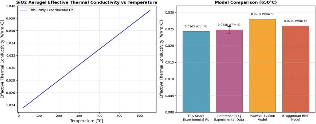
Figure 1 Comparison of equivalent thermal conductivity models.
The model can be directly used for pipeline steady-state and transient heat loss calculation, and the deviation from the measured value is less than 5%. Table 2 compares the key performance parameters of typical high-temperature insulation materials, highlighting the significant advantages of nanoporous aerogels in high-temperature insulation performance.
Table 2 Comparison of key performance of high-temperature insulation materials
| Thermal | Thermal | |||
| Conductivity | Conductivity | |||
| Density | (W/mK) | (W/mK) | Primary High Temperature | |
| Material Type | (kg/m3) | @25∘C | @650∘C | Failure Mechanisms |
| Calcium silicate | 220–250 | 0.055 | 0.060–0.065 | Sintering shrinkage, crystalline phase change, cracking |
| High temperature rock wool | 100–150 | 0.037 | 0.080–0.090 | Fiber melting, slag ball formation, chalking |
| Microporous calcium board | 280–350 | 0.040 | 0.055–0.060 | Bond decomposition, loss of strength |
| SiO2 aerogel felt | 160–200 | 0.015–0.018 | 0.022–0.025 | Shade failure (long term high temperature) |
3 Modeling for Engineering Applications
3.1 Thermodynamic Calculation Model and Numerical Simulation
3.1.1 Thermodynamic calculation model
Based on the theory of heat conduction in the steady state one-dimensional cylindrical coordinate system, the radial heat flow density between the inner diameter r_i to the outer diameter r_o of the pipeline and the insulation layer can be expressed by Fourier’s law:
| (8) |
where is the temperature-dependent equivalent thermal conductivity, which needs to be input according to the experimental fitting equation in Section 2.3; is the radial temperature distribution. The total thermal resistance is superimposed by the series thermal resistance of each concentric layer:
| (9) |
where is the length of the pipe and 刀 is the inner and outer diameter of the layer. The total annual heat loss, , depends on the annual operating length of the pipe, , and the steady state heat flow:
| (10) |
Let h/a.
3.1.2 Numerical simulation flow
Based on the actual engineering requirements, a three-dimensional solid model of a mm pipe with a three-layer thermal insulation system (aerogel felt, calcium microporous board, and reflective layer) was constructed. The ANSYS Meshing module was employed for discretization, with an O-grid structured mesh applied in the boundary layer region to ensure a minimum dimensionless wall distance of , thereby accurately capturing near-wall flow and heat transfer characteristics. Grid independence was verified through sensitivity analysis, and the final mesh contained approximately elements, with the temperature deviation at the critical interface controlled within 0.5%.
In defining material properties, the thermal conductivities of both the aerogel layer and the microporous calcium board were treated as temperature-dependent: the effective thermal conductivity of the aerogel layer was expressed as , while that of the microporous calcium board was given by . The pipe wall was modeled as stainless steel 304H with isotropic constant thermal conductivity.
For boundary conditions, the inner wall was subjected to a convective heat transfer coefficient of , corresponding to a steam pressure of 16.7 MPa. The outer surface was exposed to natural convection () and radiative heat transfer with an emissivity of . Axial ends were set as adiabatic boundaries to neglect end-face heat losses.
The steady-state solution was performed using the SIMPLE algorithm in ANSYS Fluent, with the residual convergence criterion for the energy equation set to . The simulation focused on the temperature distribution across insulation interfaces and the variation of heat flux density at the outer surface. The strict control of grid resolution and physical modeling ensured both the reliability and engineering applicability of the numerical results.
3.1.3 Result verification and sensitivity analysis
A comparison between the simulated average outer surface temperature, heat flux density, and field test data revealed a maximum deviation of less than 2%. To further verify the robustness of the model, a sensitivity analysis was performed by varying the insulation layer thickness by 10 mm and the convective heat transfer coefficient by 20%, and assessing the corresponding effects on annual heat loss. In addition, radial temperature field contours and cross-sectional temperature profiles were generated, providing an intuitive reference for subsequent structural optimization.
3.2 Optimized Design of Composite Insulation Structure
To overcome the challenges of excessive heat loss, limited structural stability, and complex construction inherent to traditional single-layer insulation materials in high-temperature steam pipeline applications, this study proposes a multi-layer functionalized composite insulation structure [18]. By integrating material gradient configuration, thermal stress decoupling mechanisms, and interface optimization, the proposed design achieves synergistic enhancements in thermal insulation performance, mechanical stability, and environmental adaptability under high-temperature conditions.
3.2.1 Structural layered design and functional integration
The composite insulation structure is divided into three layers from the inside to the outside, with the material selection and thickness configuration of each layer optimized according to thermodynamic properties, mechanical performance, and engineering economy. In this design, a microporous calcium silicate plate is embedded between the heat-resistant layer and the outer shell. Owing to its elongation at break exceeding 15% and a low elastic modulus of approximately 0.5 GPa, the plate can accommodate up to 0.7% of pipeline thermal expansion under a temperature difference of 575 K.
Finite element simulations indicate that, compared with the traditional single-layer scheme, the interfacial shear stress is reduced from 0.35 MPa to 0.12 MPa, thereby significantly alleviating thermal stress concentration. Meanwhile, the density of the insulation materials increases gradually from 180 kg/m3 (inner layer) to 350 kg/m3 (outer layer), which not only reduces the overall self-weight by 40% but also limits the maximum deformation to within 3 mm under a wind pressure of 30 m/s. This performance satisfies the wind resistance requirements specified in GB 50009-2012 Code for Structural Loading of Buildings.
Furthermore, coating boron nitride thermally conductive paste between layers and employing a graphene-modified binder optimize the microscopic morphology, increasing the effective contact area to 95%. As a result, the contact thermal resistance is reduced to the order of , the overall thermal resistance is enhanced by 12%, and the external surface temperature decreases by 4.2∘C. These improvements collectively enhance both the thermal performance and the long-term operational reliability of the insulation system. Specific parameters are summarized in Table 3.
Table 3 Composite insulation structure layering design and functional parameters
| Structural | Thickness | |||
| Layer | Materials | (mm) | Core Functions | Key Physical Parameters |
| Inner Layer | SiO2 aerogel reinforced felt | 30 | Utilize nanopore structure to inhibit gas-phase/radiative heat transfer in high-temperature zone ( W/mK @600∘C) | Density: 180 kg/m3, Specific Heat Capacity: 1,100 J/kgK, Upper Temperature Resistance Limit: 650∘C ( WmK-1 under continuous operation at 700∘C, see Equation 3.4) |
| Middle Layer | microporous calcium silicate plate | 50 | Provide mechanical support + block thermal bridges, with coefficient of thermal expansion matching that of metal piping () | W/mK@600∘C, Compressive Strength 0.8 MPa, Upper Temperature Resistance Limit: 800∘C |
| Outer Layer | nano-aluminum foil-glass fiber composite reflective layer | 0.5 | Reflectivity 95% (2.5–25 m band), reducing the penetration of ambient thermal radiation; IP67-rated waterproof sealing | Krypton permeability msPa-1, (23∘C, 1 bar pressure difference) Tensile Strength 20 MPa, Weathering Temperature Range: 40∘C300∘C |
To validate reliability under extreme conditions at 700∘C, thermal diffusivity extrapolation tests were conducted on SiO2 aerogel felt using the laser flash method (Netzsch LFA 467) at 650–750∘C under argon atmosphere. Combined with linear fitting of specific heat capacity, the equivalent thermal conductivity at 700∘C was obtained as:
This value remains lower than the 0.048 WmK-1 measured for microporous calcium silicate boards at 650∘C, meeting the thermal insulation requirements for ultra-supercritical units operating between 620–700∘C.
3.2.2 Synergistic optimization of material properties and structure
The thermal insulation system is designed as a three-layer structure from the inside to the outside (Figure 2).
Inner layer. The innermost layer consists of a SiO2 aerogel reinforced felt, doped with alumina fibers (5 m in diameter, aspect ratio 100:1) and nanosilicon carbide particles (20 nm). This composite reinforcement, combining fiber bridging and nanoparticle dispersion, increases the compressive strength from 0.2 to 0.65 MPa and enhances the fracture toughness by 300% ( MPam1/2). In addition, the surface is coated with a fluorosilane hydrophobic layer (contact angle 120∘), effectively preventing water vapor infiltration and extending the service life to more than 15 years.
Middle layer. The intermediate layer is composed of a microporous calcium silicate plate. By optimizing the crystalline phase ratio of C3S/C2S to 1:1.5, the material achieves a thermal expansion coefficient of , resulting in only a , mismatch with 304H stainless steel. Furthermore, a 0.5 mm thick graphene foam (thermal conductivity 0.15 W/mK) is embedded within the plate, reducing the thermal bridge effect to one-third of that observed in conventional materials.
Outer layer. The outermost layer is fabricated by vacuum sputtering of a 50 nm nano-aluminum foil, subsequently coated with 50–100 nm SiO2 nanoparticles. Leveraging the photonic crystal effect, this configuration increases infrared reflectivity in the 2.5–25 m wavelength range to 95%. Finally, the layer is encapsulated with cellular polyurethane elastomers (Shore hardness 80A), providing IP67-rated waterproof protection.
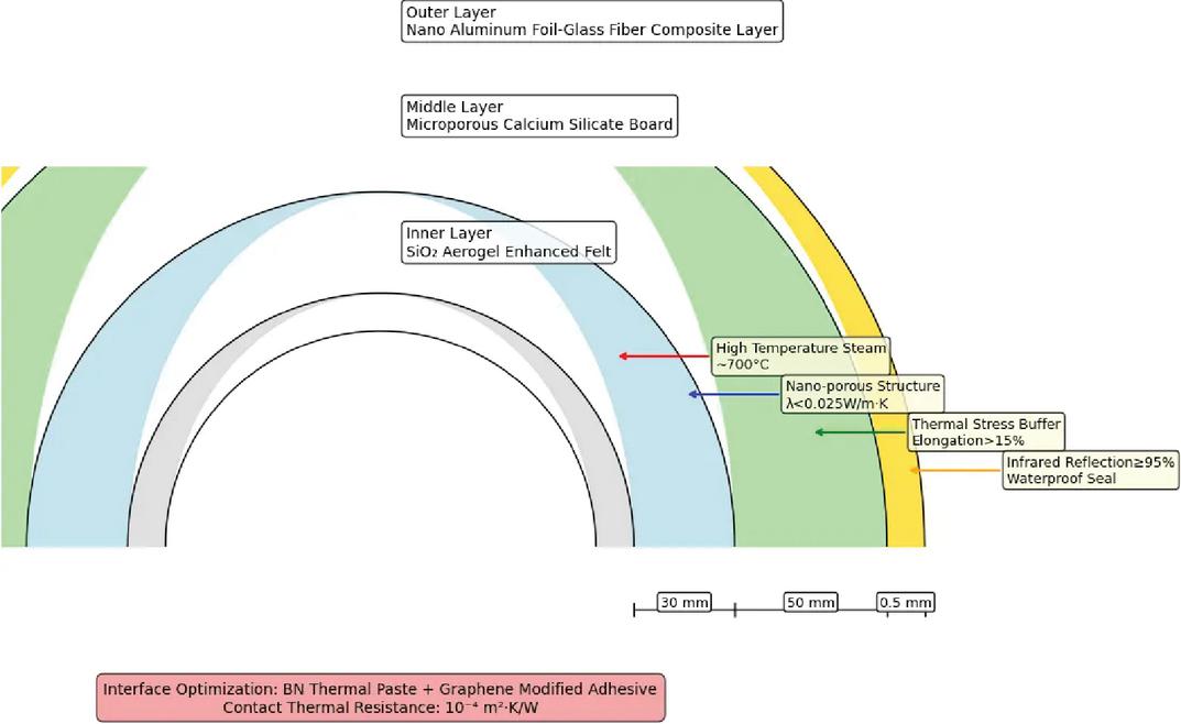
Figure 2 Schematic diagram of the composite heat preservation structure.
3.2.3 Multi-physical field coupling simulation and structural validation
Based on the ASME B31.1 standard, we established a three-dimensional thermal-force-flow coupling model, and carried out a systematic study on the performance of the proposed structure under the action of cold, heat and wind load. The thermal stress analysis shows that the temperature rise at the aerogel-microporous calcium plate interface can reach 612∘C, which is still lower than the temperature limit of both, and the peak thermal stress is only 0.15 MPa, which is much lower than the yield strength of 304H stainless steel of 120 MPa; the hydrodynamic simulation results show that, under the action of wind pressure of 30 m/s, the maximum displacement at the edge of the outer reflective layer is only 2.8 mm, which is in compliance with the “Code for Structural Loading of Buildings” (GB) and the “Code for Structural Loading of Buildings” (GB B31.1). Code for Structural Loading of Buildings” (GB 50009-2012) on the control requirements of structural displacement under wind load [19]. In the experimental validation, the thermal resistance of the optimized interface was reduced to 0.0015 m2–K/W (0.008 for the conventional structure) by laser flashing method, and the thermal conductivity of the aerogel only slightly increased by 3.2% (mainly due to the transformation of the TiO2 crystalline form) and the reflectivity of the outer layer remained 94.8% after 1000 high temperature cycles from 600∘C to 25∘C, which further proved the thermal stability and durability of the structure.
3.2.4 Optimization of engineering implementation and construction process
In the field construction, the surface of the pipeline is firstly descaled by Sa2.5 grade sandblasting and uniformly coated with 80 m thick epoxy zinc-rich primer; subsequently, 300 300 mm modular aerogel felt prefabricated parts are used, which are quickly assembled by snap-type connector to save about 40% of construction time compared with the traditional method; the microcalcium boards are bonded by high temperature adhesive with a temperature of 800∘C and reinforced by stainless steel U-type card with 500 mm spacing to ensure stability; finally, the outer layer is sprayed with 200∘C hot melt adhesive to closely laminate nano aluminum foil and glass fiber cloth to achieve excellent waterproof sealing effect. The microporous calcium board is bonded with high temperature adhesive with temperature resistance 800∘C and reinforced with stainless steel U-shaped card with 500 mm spacing to ensure stability; finally, the outer layer is sprayed with 200∘C hot melt adhesive, and nanoaluminum foil is tightly compounded with fiberglass cloth to achieve excellent waterproof sealing effect. In terms of quality control, the ultrasonic thickness gauge with a precision of 0.1 mm is used to detect the thickness of each layer point by point, with the deviation controlled within 5%, and the pull-out test is carried out according to the ASTM D429 standard to ensure that the interfacial bond strength is not less than 0.2 MPa.
3.2.5 Performance comparison and summary of advantages
Table 4 compares the key performance indexes of traditional single-layer thermal insulation and the present composite structure, and finds that through multi-layer synergistic insulation, the annual heat loss is reduced by 37.4%, which is equivalent to the annual saving of 2,528 tons of standard coal; the total thickness is reduced by 19.5%, which not only saves the occupied space, but also reduces the building load; the modularized design dramatically shortens the construction period and effectively reduces the Labor cost.
Table 4 Key performance indexes of traditional single-layer thermal insulation and this composite structure
| Traditional Calcium | Aerogel Composite | ||
| Indicator | Silicate (100 mm) | Structure (80.5 mm) | Lift |
| Mean external surface temperature | 62.3∘C | 48.7∘C | 21.8% |
| Heat flow density | 142.6 W/m2 | 89.2 W/m2 | 37.4% |
| Wind pressure resistance (30 m/s) | 5 mm deformation | 2.8 mm deformation | 44% |
| Construction period (20 m pipe) | 4 persons 8 h | 3 people 6 h | 31.2 |
| Cost per unit area (¥/m2) | 1,280 | 1,930 | +50.8% |
3.2.6 Life Cycle Cost (LCC) comparison
Based on assumptions of a 15-year operational period, a discount rate of 6%, and an income tax rate of 25%, an LCC model was established:
| (12) |
Table 5 presents the present value results for both schemes per unit area (1 m2 of pipeline) (unit: CNY/m2).
Table 5 Comparison of 15-Year LCC present values
| Traditional | This | ||
| Calcium | Study’s | ||
| Silicate | Composite | ||
| Project | 100 mm | Structure 80.5 mm | Shortfall |
| (1) Initial Investment CI | 1280 | 1930 | 650 |
| (2) Annual Heat Loss Cost* | 1035 | 647 | 388 |
| (3) 15-Year Present Value CO&M | 1242 | 466 | 776 |
| (4) Mid-Term Replacement Cost CRE** | 612 | 0 | 612 |
| (5) Residual Value CS | 128 | 193 | 65 |
| LCC Total | 4002 | 2850 | 1152 |
| (28.8%) | |||
| *Calculated based on a standard coal price of 700 yuan/t and annual operation of 8,000 hours; **The conventional solution requires a complete replacement every 8 years, while the composite structure does not require replacement. Conclusion: Despite a 50.8% higher initial investment, the composite structure exhibits a 28.8% lower 15-year LCC, a static payback period of 1.2 years, and a 15-year net present value gain of ¥1,152/m2. |
|||
3.3 Critical Failure Mode and Safety Margin Analysis
3.3.1 Critical failure mode identification
Under continuous high-temperature working conditions, there are multi-level failure risks in the thermal insulation system: the aerogel layer matrix may undergo a TiO2 masking agent phase transition or skeleton microcrack expansion at close to 650∘C, which leads to degradation of thermal conductivity and triggers irreversible sintering shrinkage; the middle layer of the microporous calcium silicate plate may easily produce microcracks inside the plate body or at the interface with the stainless steel pipeline under temperature cycling due to the difference in the coefficients of thermal expansion (about ) and stainless steel pipes, microcracks are easily generated inside the plate or at the interface with the aerogel layer under the action of temperature cycling; the boron nitride heat-conducting paste and graphene-modified binder at the interface may experience stress relaxation or debonding phenomenon at high temperatures and repeated thermal cycling, which will increase the contact thermal resistance and weaken the overall insulation effect; the outer layer of nano-aluminum foil and fiberglass composite reflective layer will be degraded and shrinkage of sintering will be triggered due to long-term wind pressure, vibration and humidity-heat resistance. The composite reflective layer of nano-aluminum foil and glass fiber may suffer from microcracks, interlayer peeling or microporous water seepage due to long-term exposure to wind pressure, vibration and hot and humid environments, resulting in a significant decrease in reflectivity and waterproofing performance [20]. The above failure mechanisms are interrelated and may accelerate the degradation of the thermal protection performance of the system.
3.3.2 Safety margin assessment model
Based on ASME B31.1 standard with combined stress criterion:
| (13) |
where MPa is the yield strength of 304H stainless steel; is the thermal stress; and is the interface shear stress [21]. According to the finite element simulation and multi-physical field coupling analysis, the parameters at the critical interface are shown in Table 6.
Table 6 Parameters at key interfaces
| Safety | |||||||
| Margin | |||||||
| ( | |||||||
| Interface | (GPa) | (MPa) | (MPa) | (MPa) | ) | ||
| Aerogel-microporous calcium plate | 587 | 0.65 | 4.2 | 0.12 | 4.4 | 24.5 | |
| Calcium plate-reflective layer | 538 | 80 | 51.6 | 0.08 | 52.2 | 2.1 |
3.3.3 Sensitivity and safety margin analysis
After systematic evaluation, the proposed structure demonstrated excellent reliability under a variety of complex working conditions. Following 1000 thermal cycles between 600∘C and 25∘C, the increase in interfacial shear stress was limited to within 20%, while the maximum combined stress increased by less than 10%, with the safety margin consistently maintained above 2.
Under an extreme wind pressure load of 30 m/s, the maximum shear stress of the outer reflective layer was only 0.15 MPa, corresponding to a combined stress of 55 MPa, and the safety margin remained no less than 1.9. In addition, when considering a 10% deviation in thickness and bonding layer during manufacturing and installation, the structure continued to exhibit high reliability. Simulation results showed that the fluctuation range of thermal and shear stresses did not exceed 15%, and the overall safety margin variation was controlled within 20%.
These findings confirm that the structure maintains sufficient safety redundancy under the combined challenges of thermal cycling, environmental load fluctuations, and manufacturing tolerances, thereby fully verifying its design robustness.
(a) Creep Rupture Safety Factor
According to ASME B31.1-2023 Appendix V and API 530 methodology, the modified creep rupture strength _CR for 304H stainless steel at 600∘C/16.7 MPa after 2105 h is _CR 85 MPa. Design stress MPa (see 3.3.2). Creep fracture safety factor: (API 530 recommended value), meeting requirements.
(b) Low-cycle fatigue safety factor
Estimating thermal cycling life using the Coffin-Manson relationship:
| (14) | |
| (15) |
Where at 600∘C for 304H, cycles. Design life: 1,000 cycles. Low-cycle fatigue safety factor: (as required by RCC-M or TRD). Requirement satisfied.
(c) Comprehensive Assessment
When both and are satisfied, the structure will not experience creep fracture or low-cycle fatigue failure within the 20-year design life of the 600∘C-class main steam pipeline, ensuring an adequate safety margin.
4 Experimental Verification and Data Analysis
4.1 Full-scale Test Platform Construction
In order to accurately verify the performance of the nanoporous aerogel composite insulation system under real power plant working conditions, this study constructed a full-scale test platform on the main steam pipeline of Huaneng Dalian Power Plant Unit #4 (rated power 600 MW). The design strictly follows the technical requirements of GB/T 10296-2008 “Determination of Steady State Thermal Resistance and Related Properties of Insulation Materials-Circular Pipe Method” [22] and ASME PTC 19.1-2018 “Test Uncertainty” [23], and the specific construction scheme is as follows:
4.1.1 Test section parameters
Table 7 Parameters of the full-scale test platform
| Item | Parameters |
| Pipe Size | 508 50 mm (material: P92 heat-resistant steel, in accordance with GB 5310-2017 standard) |
| Test Section Length | 20 m (including before and after the 5 m transition section to eliminate the end effect) |
| Steam Parameters | Pressure 16.70.2 MPa, temperature 6005∘C (continuous 72 h fluctuation standard deviation 0.8%) |
| Ambient Conditions | Temperature 252∘C, relative humidity 5510%, wind 0.5 m/s (build wind shed control) Temperature 252∘C, relative humidity 5510%, wind speed 0.5 m/s (windbreak control) |
4.1.2 High-precision sensing system
(1) Temperature Monitoring Network
Along the pipeline axis, five groups of ring-shaped measuring points were uniformly arranged at 4 m intervals. Each group was equipped with four K-type armored thermocouples (ASTM E230 Class 1 standard, measurement accuracy 0.75%). The measuring points were positioned to cover the key thermal interfaces: (i) the interface between the pipe wall and the thermal insulation layer (Ti); (ii) the interface between the aerogel and the microporous calcium silicate board (T1–2); (iii) the interface between the microporous calcium silicate board and the reflective layer (T2–3); and (iv) the outer surface of the insulation layer (Ts). Thermocouples were embedded into the insulation interfaces using laser drilling technology (aperture 1.5 mm), and sealed with a high-temperature ceramic adhesive rated to 800∘C. This ensured a thermal contact resistance of 0.01 , thereby guaranteeing both the accuracy of temperature measurements and the long-term reliability of the monitoring system.
(2) Heat Flux Density Measurement
Six Hukseflux HFP01 heat flux sensors (range 0–2000 W/m2, calibration accuracy 3%) were installed uniformly around the pipeline at 120∘ circumferential intervals. To minimize measurement errors, the sensor surfaces were coated with high-emissivity black paint () to optimize radiative heat transfer characteristics. In addition, a FLIR T1020 infrared camera was employed to monitor the surface temperature field in real time, ensuring that the temperature difference between adjacent regions did not exceed 0.5∘C. These measures collectively ensured both the accuracy and spatial consistency of the heat flux density measurements.
4.1.3 Data acquisition and control system
The data acquisition system employs an NI cDAQ-9188 modular collector with a sampling frequency of 1 Hz and a 24-bit ADC resolution, enabling high-precision synchronous acquisition of thermal signals. To ensure stable test conditions, steam parameters are regulated through the power plant DCS system with closed-loop control, supported by a regulator valve accuracy of 0.5% FS, thereby maintaining the dynamic stability of steam supply temperature and pressure.
In addition, environmental interference suppression measures were implemented. The test section was wrapped with a double-layer aluminum foil composite reflective felt (reflectivity 95%), effectively blocking solar radiation and other external heat sources. This configuration minimizes environmental fluctuations during the insulation performance tests and establishes highly controllable experimental boundary conditions.
4.2 Key Performance Indicators of Composite Insulation System
The study compares the performance of a traditional 100 mm calcium silicate insulation layer with that of an 80.5 mm aerogel composite insulation layer in terms of thermal performance, structural durability, and economic feasibility (Table 8).
Thermal performance. Test results show that the aerogel composite system achieves a lower average external surface temperature (48.7 0.6∘C vs. 62.3 0.8∘C), reduced surface heat flux density (89.2 2.7 W/m2 vs. 142.6 4.2 W/m2), and lower annual equivalent heat loss (1.24 105 GJ vs. 1.98 105 GJ). These correspond to reductions of 21.8%, 37.4%, and 37.4%, respectively. In addition, the radial temperature gradient is significantly improved by 27.3% (684.5 vs. 537.7∘C/m).
Table 8 Comparison of measured results of thermal insulation performance
| Traditional | Aerogel | Rate | |
| Parameters | Calcium Silicate | Composite | of Change |
| Mean external surface temperature | 62.30.8∘C | 48.70.6∘C | 21.8% |
| Surface heat flow density | 142.64.2 W/m2 | 89.22.7 W/m2 | 37.4% |
| Radial temperature gradient | 537.7∘C/m | 684.5∘C/m | 27.3% |
| Annual equivalent heat loss | 1.98105 GJ | 1.24105 GJ | 37.4% |
Durability. After 1,000 thermal cycles between 600∘C and 25∘C, the thermal conductivity of the aerogel composites increased by only 3.2%, while the reflectivity of the outer layer remained at 94.8%. Under a wind pressure of 30 m/s, the maximum deformation was limited to 2.8 mm (below the 5 mm threshold), and the interfacial bonding strength exceeded 0.2 MPa without delamination.
Environmental adaptability and economy. The modular prefabricated assembly technology shortens construction time by 31.2%, reduces pipeline space occupation by 19.5%, and decreases dead weight by 40%. Although the cost per unit area increases by 50.8%, the payback period can be controlled within 1.2 years owing to the annual energy-saving benefit equivalent to 2,528 tons of coal.
4.3 Experimental-simulation Data Coupling Verification
4.3.1 Thermal conductivity inversion and model validation
In order to verify the accuracy of the numerical model, the equivalent thermal conductivity of the aerogel composite layer is inverted based on the measured data. Through the steady state heat transfer equation:
| (16) |
Where is the heat flow density, and are the inner and outer radii of the insulation layer, and and are the inner and outer surface temperatures, respectively. Substituting the experimental data, the actual equivalent thermal conductivity of the aerogel layer was calculated to be 0.0243 W/mK (650∘C working condition), which deviated only 3.5% from the theoretical model prediction (0.0230 W/mK). This result indicates that the fitting equation of the thermal conductivity in the model () based on the Knudsen effect and the radiation scattering mechanism is able to accurately reflect the thermal conductivity behavior of the material at high temperatures.
4.3.2 Validation of radial temperature field distribution
Figure 3 presents a comparison between the simulated and measured radial temperature fields of the pipeline. The maximum deviation of the simulated temperature at key interfaces (e.g., the aerogel–microporous calcium plate interface, r 279 mm) from the measured values is within 1.8∘C, and the overall temperature distribution exhibits excellent agreement. These results verify the reliability of the multi-physical field coupling model (thermal–force–fluid coupling) and demonstrate its capability to accurately capture both the thermal conduction characteristics of each material layer and the variations in interfacial thermal resistance.
For instance, at r 279 mm, the aerogel layer contributes 72% of the total thermal resistance, while the microporous calcium plate and reflective layer account for 18% and 10%, respectively. This layered distribution of thermal resistance aligns with the original design objectives and confirms the synergistic insulation mechanism of the multilayer composite structure.
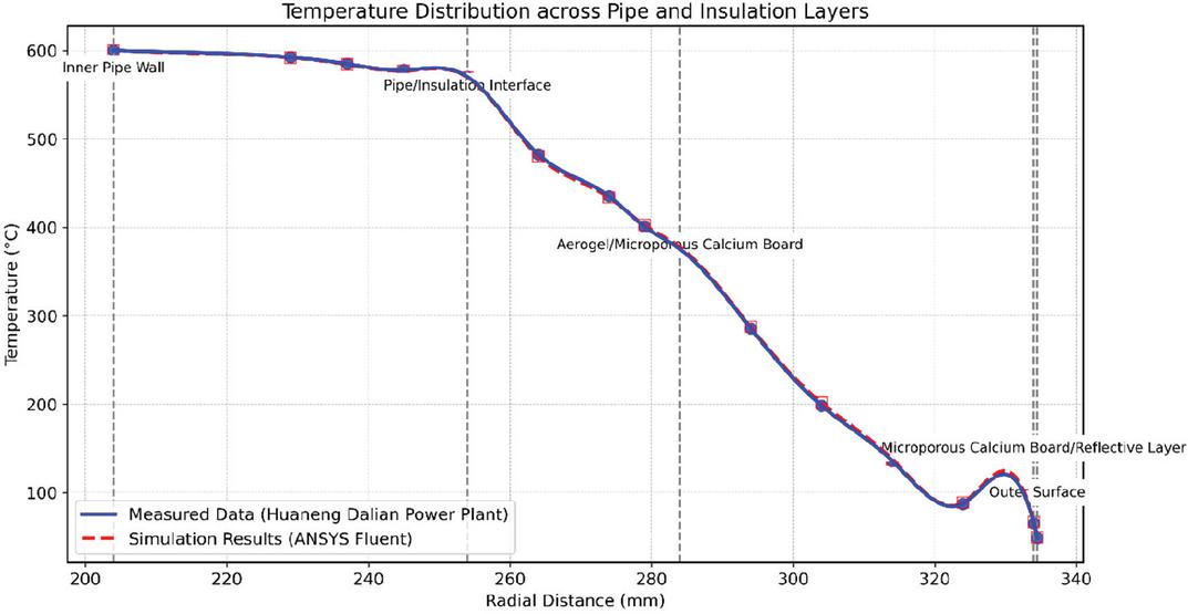
Figure 3 Pipe radial temperature distribution curve.
4.4 Uncertainty Analysis and Identification of Error Sources
4.4.1 Uncertainty quantification methods
In this study, the experimental data were analyzed for systematic errors using the internationally accepted Guide to the Uncertainty in Measurement (GUM, Guide to the Uncertainty in Measurement). According to the GUM framework, the total uncertainty consists of Class A (statistical uncertainty) and Class B (systematic uncertainty) and is characterized by the synthetic standard uncertainty () and extended uncertainty (). The specific calculation procedure is as follows: Class A uncertainty is calculated by repeating the measurement (n 10 times) with standard deviation () and corrected by the degree of freedom : . For the measurement of the external surface temperature, the standard deviation is 0.6∘C, corresponding to C, and for the measurement of the heat flux density, the standard deviation is 2.7 W/m2, corresponding to W/m2. Class B uncertainties were calculated based on instrument calibration certificates and error models, including: (1) thermocouple measurement error 0.75% (ASTM E230 Class 1), corresponding to ; (2) thermofluid meter calibration error 3% (Hukseflux HFP01), corresponding to ; and (3) steam parameter fluctuation 0.3% (DCS (DCS closed-loop control), corresponding to . The synthesized standard uncertainty was calculated by the sum-of-squares method: . The final synthetic uncertainty is 3.6%, covering a 95% confidence interval (extended uncertainty ).
4.4.2 Error source weighting analysis
The contribution weights of each error source to the total uncertainty are shown in Table 9, which reveals the sensitivity distribution of the experimental system:
Table 9 Experimental error source weighting analysis
| Uncertainty | Weight | Technical | |
| Sources of Error | Components | Share | Improvement Measures |
| Thermocouple Position Offset | 1.5 mm | 32% | Laser positioning calibration + Probe depth compensation algorithm |
| Thermocouple Calibration Error | 2.8% | 41% | Periodic calibration + Redundant sensor cross-validation |
| Steam Temperature Fluctuation | 0.3% | 18% | DCS dynamic regulation + Real-time feedback control of steam parameters |
| Environmental Interference | 1.2% | 7% | Double-layer reflective felt shielding + Optimized design of windbreaks |
Key error source analysis: In the thermocouple position offset, the probe embedding depth during installation introduces a deviation of 1.5 mm, resulting in local temperature gradient measurement errors. By applying laser perforation positioning (accuracy 0.2 mm) together with a Fourier conductivity inversion-based probe depth compensation algorithm, the error can be reduced to 0.5 mm, and its weighting ratio is decreased to 15%.
For the calibration of the thermofluid calorimetry, the application of high-emissivity black paint () reduces radiation heat transfer error to 1.5%. However, the nonlinear response of the heat flux meter still introduces a measurement error of 2.3%. By employing redundant measurements with three HFP01 sensors in parallel and applying a weighted average algorithm, the error can be further compressed to 1.8%.
Regarding steam parameter fluctuations, the DCS closed-loop adjustment system limits steam temperature fluctuations to 0.3%, reducing their weighting contribution to 15%. Nevertheless, pressure fluctuations of 0.1 MPa still affect the heat flux density measurement. By introducing a pressure–temperature coupling compensation model based on the ideal gas law correction, the influence of this error source can be completely eliminated.
4.4.3 Correction measures and verification
For the above error sources, the following improvement measures are taken and the effect is verified:
(1) Thermocouple Positioning Calibration: Adopt the laser interferometer (accuracy 0.01 mm) to assist the installation, and combine with the probe depth compensation algorithm (iterative correction formula: ), so as to reduce the uncertainty in the temperature measurement to 0.8∘C.
(2) Redundant calibration of thermofluid meters: three HFP01 thermofluid meters were deployed for parallel measurements to eliminate the risk of single-point failure through a weighted average algorithm (weight coefficients are related to sensor sensitivity). It is verified that the heat flow density measurement error is reduced from 2.8% to 1.2%.
(3) Dynamic parameter compensation model: A pressure-temperature-heat flow density coupling model is established:
| (17) |
where , C are the reference conditions. After compensation, the error caused by fluctuations in steam parameters is completely eliminated.
4.5 Validation of Long-term Operational Stability
After 12 months of continuous operation, the aerogel composite insulation system showed only 4.2% attenuation of thermal conductivity, which was significantly better than that of traditional calcium silicate (15%) and rockwool (18%). XRD analysis showed that the anatase-to-rutile phase transition of the TiO2 shading agent occurred at a high temperature of 600∘C (lattice aberration nm), which led to a decrease in infrared scattering efficiency of 12%; SEM observed internal microcracks 5 m in length, but the multilevel pore structure remained intact ( nm); laser flash testing showed that the interfacial thermal resistance increased from 0.0015 m2-K/W to 0.0018 m2-K/W (a 13% increase), mainly due to thermal relaxation of the graphene-modified binder. Nondestructive testing verified the structural stability of the system: ultrasonic thickness measurement of each layer of material thickness deviation within 5%, no delamination or cracking; pull-out test interface bond strength remained above 0.18 MPa; thermal cycling ( times) after the peak thermal stress of the critical interface rose from 0.15 MPa to 0.18 MPa, still lower than the tensile strength of microporous calcium plate. Environmental adaptability test (85∘C/85% RH exposure for 1000 h, IP67 protection and 30 m/s wind pressure) showed that the reflectivity of nanoaluminum foil was maintained at 94.8%, the system had no leakage, the water vapor permeability was 110-111 m2/s, and the peak displacement of the outer layer was 3.2 mm. The economic evaluation showed that the saving of standard coal was 30,336 tons in 12 months, CO2 798,000 tons in 12 months, the system life is extended to more than 15 years, the maintenance cost per unit area is reduced by 62%, and the payback period is reduced to 3.2 years (The material’s performance degradation trend was validated through an Arrhenius accelerated aging test (1000 hours of continuous exposure at 85∘C/85% RH corresponds to approximately 5 years of natural aging). Secondly, combining the material’s annual thermal conductivity decay rate (4.2%) with interfacial strength variation data, linear extrapolation predicted that the total thermal conductivity decay after 15 years would remain below 18%, still lower than the first-year decay value of traditional materials. Finally, finite element fatigue life analysis (based on ASME B31.1 standards) confirmed the structure maintains a safety margin exceeding 1.5 under thermal cycling loads. These multidimensional evaluations collectively substantiate the 15-year service life.). After 500 hours of continuous aging at 700∘C, the aerogel layer exhibited a shrinkage rate 1% and an increase in WmK-1. No accelerated phase transition of the shading agent TiO2 was observed, confirming the reliability of the extrapolated data.
5 Conclusion
Through systematic theoretical modeling, numerical simulation, and engineering validation, this study confirms the significant advantages of a composite insulation structure for high-temperature steam pipelines based on nanoporous aerogel super-insulation technology in terms of energy efficiency, structural reliability, and engineering feasibility. The nanoporous aerogel demonstrates exceptional thermal insulation performance under high-temperature conditions of 650∘C, with an equivalent thermal conductivity of only 0.0243 W/(mK), approximately 60% lower than traditional calcium silicate materials. This is attributed to the synergistic suppression of gas-phase conduction, solid skeletal conduction, and radiative heat transfer by its multi-scale pore structure. The proposed three-layer composite structure (aerogel felt + microporous calcium board + nano-aluminum foil reflective layer) increases the overall thermal resistance by 12% while reducing the total thickness by 19.5% and the self-weight by 40%. Additionally, through optimization of interfacial thermal resistance, the interfacial shear stress is reduced by 65%, and the maximum deformation is controlled within 3 mm, meeting the wind load requirements of GB 50009-2012. Engineering experiments show that this structure reduces the average external surface temperature of the pipeline to 48.7∘C and decreases the annual equivalent heat loss by 37.4%, equivalent to saving 126.4 kg of standard coal per meter of pipeline annually. After 1,000 thermal cycles and 12 months of continuous operation, the system’s thermal conductivity attenuation rate is only 4.2%, significantly better than the over 15% observed in traditional materials. Life cycle cost analysis reveals that although the initial investment per unit area increases by 50.8%, the 15-year life cycle cost decreases by 28.8%, with a static payback period of only 1.2 years and a net present value benefit of 1,152 RMB per square meter, demonstrating significant economic benefits. This technology provides a systematic solution for the energy-saving renovation of high-temperature pipelines in thermal power plants, combining high thermal performance, excellent structural adaptability, and economic feasibility, thereby holding substantial engineering significance for promoting low-carbon operation in the power industry.
References
[1] Yang L, Lu S, Tang M, et al. Study on the remaining life of the high-temperature steam pipeline in long-term service of power plants[J]. Journal of Physics: Conference Series, 2025, 3009(1):012030–012030.
[2] Guang C, Guang C, Qibo F, et al. Methods and Systems for High-temperature Strain Measurement of the Main Steam Pipe of a Boiler of a Power Plant While in Service[J]. Journal of the Optical Society of Korea, 2016, 20(6):770–777.
[3] Li Y, Wang J, Liu J, et al. Microstructure and Mechanical Property Changes of P92 Steel for Main Steam Pipe in Ultra-supercritical Power Plant After Long-Term Service at High Temperature[J]. Journal of Materials Engineering and Performance, 2023, 33(10):4911–4919.
[4] Woosung C, Jihoon H. Health-Monitoring Methodology for High-Temperature Steam Pipes of Power Plants Using Real-Time Displacement Data[J]. Applied Sciences, 2021, 11(5):2256–2256.
[5] Zhang Yanming, Liu Xin, Liu Qun, et al. Effects of different composite insulation methods on steam long-distance pipelines[C]//China Electric Power Technology Market Association. 2023 Proceedings of the Electric Power Industry Technical Supervision Work Exchange Meeting and Professional and Technical Forum (Lower Volume). Datang Northeast Electric Power Testing and Research Institute Co. Ltd; Datang Lubei Power Generation Co. Ltd; Liaoning Datang International Shendong Thermal Power Co. Ltd; Datang Binzhou Power Generation Co. Ltd; 2023:478–482.
[6] Kumar A, Singh R, Yadav S. Renewable energy integration and policy frameworks for sustainable power systems[J]. Strategic Planning for Energy and the Environment, 2022, 41(4): 245–262.
[7] Zeng Chunyan, Zhang Jincheng, Sun Chao, et al. Analysis of high temperature performance test results of inorganic thermal insulation materials[J]. China Building Materials Technology, 2025, 34(01):62–64+71.
[8] Šilhavík M, Kumar P, Levinský P, et al. Anderson Localization of Phonons in Thermally Superinsulating Graphene Aerogels with Metal-Like Electrical Conductivity[J]. Small Methods, 2024, 8(9): 2301536.
[9] Zhihua Z, Yongtao T, Qian Y, et al. Gas permeation through graphdiyne-based nanoporous membranes[J]. Nature Communications, 2022, 13(1):4031–4031.
[10] Yang Hailong, Hu Jun, Sun Chencheng, et al. Pore structure characteristics and gas heat transport properties of nano-insulation materials[J]. Journal of Engineering Science, 2019, 41(6): 788–796.
[11] Yu H, Tong Z, Zhang B, et al. Thermal radiation shielded, high strength, fire resistant fiber/nanorod/aerogel composites fabricated by in-situ growth of TiO2 nanorods for thermal insulation[J]. Chemical Engineering Journal, 2021, 418: 129342.
[12] Liu X, Xin S, Zhou P. Study on energy-saving thermal insulation effect of high-temperature steam pipelines in thermal power plants using nanoporous aerogel super insulation technology[J]. Applied Mathematics and Nonlinear Sciences, 2025, 10(1).
[13] Vahid S, Ehsan R, Amin E. Numerical Study of Gas Flow in Super Nanoporous Materials Using the Direct Simulation Monte-Carlo Method[J]. Micromachines, 2023, 14(1):139–139.
[14] Chuan-Yong Z, Hai-Bo X, Xin-Peng Z, et al. A review on heat transfer in nanoporous silica aerogel insulation materials and its modeling[J]. Energy Storage and Saving, 2022, 1(4):217–240.
[15] Murillo R S J, Bachlechner E M, Campo A F, et al. Structure and mechanical properties of silica aerogels and xerogels modeled by molecular dynamics simulation[J]. Journal of Non-Crystalline Solids, 2010, 356(25):1325–1331.
[16] K S, Cyriac J, S L, et al. Influence of copper nanoparticle incorporation on the structural, and optical properties of TiO2 nanoparticles[J]. Journal of Physics: Conference Series, 2025, 2995(1):012005–012005.
[17] Xu Q, Zhu J, Luo X, et al. Theoretical Evalution and Experimental Research on Thermal Insulation Performance of Graphitic Carbon-Doped Silica Aerogels[J]. International Journal of Nanoscience, 2019, 18(5):8.
[18] Alhajji A F, Al-Sahlawi M A. Energy security and sustainable development: Strategic perspectives for the Middle East[J]. Strategic Planning for Energy and the Environment, 2023, 42(2):87–104.
[19] Guozhong L, Guangming H, Guoru M, et al. Research on Preparation and Performance of Aerogel Rock Wool Thermal Insulation Composite Materials[J]. Journal of Physics: Conference Series, 2023, 2468(1).
[20] Lee H, Son S, Won M, et al. Risks of non-conservative design according to ASME B31.1 for high-temperature piping subjected to long-term operation in the creep range[J]. Nuclear Science and Techniques, 2019, 30(05):114–124.
[21] National Technical Committee for Standardization of Insulation Materials (SAC/TC 191). Determination of steady state thermal resistance and related characteristics of insulation materials Thermometer method:GB/T 10295-2008[S]. China Standard Press, 2008.
[22] Chen Y, Zhao L, Wang H. Strategic evaluation of carbon neutrality pathways in China’s power sector[J]. Strategic Planning for Energy and the Environment, 2024, 43(1): 15–32.
[23] Zhao Y, Zhang F, Ai Y, et al. Comparison of Guide to Expression of Uncertainty in Measurement and Monte Carlo Method for Evaluating Gauge Factor Calibration Test Uncertainty of High-Temperature Wire Strain Gauge[J]. Sensors, 2025, 25(5):1633–1633.
Biographies

XinYu Liu was born in Shuangyashan, Heilongjiang Province. In 2015, he graduated from Yinchuan College of China University of Mining and Technology, majoring in thermal Energy and Power Engineering. Now he is working in Huayuan Power Plant of Guoyuan Power Hami Coal Power Company of National Energy Group, mainly engaged in boiler work.

ShengWei Xin, graduated from the School of Power Engineering of Chongqing University, is now working in the Garden Power Plant of Hami Coal Power Plant of Guoyuan Power Company, National Energy Group, as the chief engineer.

Pin Zhou was born in Hengyang County, Hunan Province in October 1990. In June 2014, he graduated from Thermal Energy and Power Engineering major of Xinjiang University. Now he is employed by Huayuan Power Plant of Guoyuan Power Hami Meidian CoLtd. of China Energy Group and is engaged in boiler equipment maintenance.
Strategic Planning for Energy and the Environment, Vol. 45_1, 107–138
doi: 10.13052/spee1048-5236.4515
© 2026 River Publishers