Real Time Demand Driven Performance Assessment of Direct Coupled HESS for Electric Vehicles
Chailsy Sharma1,*, Sulata Bhandari1, Sandeep Kaur1 and Shimi S. L.2
1Punjab Engineering College (Deemed to be University), Sector – 12 Chandigarh, India
2Indian Naval Academy, Ezhimala, Kannur, Kerala, India
E-mail: chailsysharma@gmail.com; sulatabhandari@pec.edu.in; sandeepkaur@pec.edu.in; shimi.1980@navy.gov.in
*Corresponding Author
Received 30 September 2025; Accepted 13 April 2026
Abstract
Multi-converter-based architectures are common in hybrid energy storage systems used in electric vehicles, increase a high cost, high power losses, and high weight. The current work presents a conceptual break to such traditional designs with a direct-coupled HESS that incorporates a proton exchange membrane fuel cell, a lithium-ion battery, and a supercapacitor into one DC bus so that the interconnection power converters are not required. This suggested configuration is based on the new demand-driven model, where the distribution of power is determined depending on the actual load requirements and without referring to predictive algorithms. The proposed system was modeled to evaluate the feasibility of this approach and was heavily simulated in an environment based on MATLAB/Simulink, with three standardized drive cycles FTP75, EPA Highway and WLTC Class. The performance is shown with EMS distribution efficiency of 94.8% and response time of 3.2 milliseconds. It also shows a more stress-free architecture of components, 55.7% decrease in peak current of the battery and better capacity retention. Through successful decoupling of power distribution and predictive models, the results demonstrate that a simplified, converter-free topology is a high-performance alternative providing a possible future, more solid, efficient, and commercially viable route to more robust and efficient powertrains in electric vehicles.
Keywords: Hybrid energy storage systems (HESS), electric vehicles (EV), proton exchange membrane fuel cell (PEMFC), direct coupled, energy management.
1 Introduction
Around the world, the transportation industry represents about 24% of all CO 2 emission as a result of energy use, and internal combustion engines have efficiencies that are lower than 25%. The push of this environmental imperative has increased the production of electric vehicles (EVs) and fuel-cell electric vehicles (FCEVs) as alternatives that are sustainable. The efficiencies are significantly higher in FCEVs, being between 40 and 60 per cent compared to regular vehicles, but it is faced with severe issues in reacting to instantaneous power needs when subjected to real world driving conditions [1].
The disadvantages of single-source systems are overcome by hybrid energy storage systems, which combine several technologies to provide a promising solution to the limitations of the single-source energy storage combination. These systems combine proton exchange membrane fuel cells (PEMFCs), lithium-ion batteries, and supercapacitors and take advantage of complementary properties of both technologies: fuel cells offer large energy density and sustained power production; batteries offer moderate power density with large energy storage; and supercapacitors offer large power density at short-term demand [2, 3].
Traditional HESS architectures require several DC-DC converters and static power sharing strategies, which result in significant efficiency losses and poor real-time adaptability. For better power distribution, recent research has focused on sophisticated energy management strategies such as model predictive control, reinforcement learning, and fuzzy logic control. However, in all these methods, the use of intermediary power electronics results in conversion losses and increases the system’s complexity [4, 5].
The present study adopts a novel demand-driven framework for energy storage evaluation instead of the conventional power-centric approach. With a direct-coupling architecture and real-time demand-driven operation, the proposed system provides better performance metrics compared to those using intermediary converters. This approach allows real-time responding to load demands, hence providing better efficiency, transient handling, and overall system integration.
1.1 HESS for Electric Vehicles
Recent developments in HESS have focused on achieving maximum exploitation of different technologies. A general energy management algorithm for the integration of multi-sources is proposed by Moualek et al., showing the function of PEMFC as a main power source and battery and supercapacitor as secondary power sources [6]. In this system, the coupling of PEMFC to the DC bus is avoided before the battery voltage reaches critical values to optimize fuel cell usage.
Advanced HESS control strategies have received significant attention. Larijani et al. propose a new, effective control strategy for the HESS without a priori knowledge of driving cycles [7]. Improved battery current tracking and regulation of supercapacitor voltage are reported through a supervisory control framework.
The MPC-Differential Evolution-based energy management strategy in HESS therefore holds immense promise to reduce battery degradation and improve overall system durability. The fundamental advantage of HESS lies in its ability to match the high energy density of fuel cells and batteries with the high-power density and rapid response of supercapacitors, thereby optimizing both energy efficiency and system longevity [8].
1.2 Model Predictive Control in Hybrid Systems
Model Predictive Control has established its leading methodology in optimizing Hybrid Energy Storage Systems. Jia et al. developed a real-time model predictive control strategy for battery-supercapacitor HESS utilizing linear parameter-varying models for superior performance in power loss minimization and battery degradation mitigation [9]. The presented approach succeeds in reformulating the optimization problem as quadratic programming for efficient real-time implementation.
Advanced MPC approaches have been extended to different hybrid configurations. Li et al. proposed an online extremum-seeking-based optimized energy management strategy with consideration of fuel cell degradations for a HESS [10]. The proposed method reduces the current ripple phenomena while improving the stability and response characteristics. Chen et al. developed a real-time optimal energy management approach for fuel cell/battery hybrid systems, balancing efficiency and durability objectives [11].
The MPC-based energy management strategy has shown significant improvement in transient performance and efficiency optimization for HESS. A multi-objective, holistic framework that addresses energy minimization, component degradation reduction, and system stability maintenance is considered.
1.3 Direct Coupling and Converter-less Architectures
Direct-coupling architectures have therefore received academic interest because of their potential for reducing conversion losses. Studies in various hybrid configurations have indeed proved that simplification of the system reduces hardware complexities with no significant compromise on the performance level [12]. The direct-connection strategy even reduced the electrical system design complexity and vehicle weight by eliminating some components [12].
Comparative analyses of AC-coupled systems versus DC-coupled systems for electric vehicle charging with battery energy storage demonstrated strong efficiency advantages of DC coupling. Direct DC power paths provided nearly 4–8% increased round trip efficiency over AC-coupled schemes and in particular benefited applications of high utilization.
Supercapacitor-fuel cell hybrid power systems have been evaluated; it was demonstrated that direct-coupling configurations can provide the performance of the vehicle required and remove converter-related losses [13]. Practical feasibility Converter-free hybrid architectures were proved to be practically feasible through experimental validation [13].
1.4 Performance Metrics and Benchmarking
The use of hybrid energy- storage systems (HESS) which include both batteries and supercapacitors have demonstrated great cost-saving compared to the conventional systems [14]. The research also developed requisite evaluation models in order to have a systematic performance comparison across various configuration of the system [14].
Optimization in wind power economic dispatch: In a battery supercapacitor HESS model, optimal operations on a utility scale were achieved with adaptive control methods. The optimization methodologies minimized life-cycle costs whilst sustaining beneficial depth-of-discharge patterns of utilization [15].
This body of literature presents a significant gap in the documentation of the quantitative performance measures. Many studies focus on overall efficiency improvement instead of individual response times, tracking performance, or data of drive cycles, which highlights the need to consider all evaluation frameworks [1, 16].
1.5 Recent Advances and Emerging Trends
Recent literature has increasingly focused on advanced control strategies and system optimization. Xing et al. addressed thermal management of proton exchange membrane fuel cells in hybrid automotive vehicles, highlighting the importance of integrated thermal and electrical management [17].
Advanced energy management systems have begun incorporating road gradient and terrain information to improve performance. Sayah et al. developed an advanced EMS with road gradient consideration for fuel cell hybrid electric vehicles, demonstrating improved efficiency through predictive terrain-aware control [18].
Performance enhancement through intelligent control and optimization has been a consistent theme. Sharf et al. demonstrated performance enhancement of hybrid battery-supercapacitor EV energy storage systems through optimized control strategies [19]. Staņa et al. proposed adaptive energy management control for efficiency improvement of supercapacitor-based energy recovery systems, showing the potential for real-time adaptive approaches [20].
1.6 Research Gaps and Motivation
Despite significant advances in HESS technology and energy management strategies, several critical gaps remain. Most existing systems rely on multi-converter architectures that introduce substantial conversion losses, typically ranging from 5–15% depending on the number of conversion stages and operating conditions [21]. These architectures also increase system weight, cost, and complexity, limiting the commercial viability of HESS for mass-market electric vehicles.
Furthermore, many advanced EMS approaches depend on complex predictive algorithms, machine learning models, or optimization routines that require significant computational resources and extensive training data [22]. While these methods can achieve high performance under specific conditions, they may lack robustness when faced with driving patterns that differ significantly from training scenarios.
Recent studies have begun exploring simplified architectures and demand-driven approaches. Agati et al. investigated the effect of degree of hybridization and energy management strategy on fuel cell/battery vehicle performance in real-world driving cycles, highlighting the importance of practical, implementable solutions [22]. ElGhanam et al. evaluated hybrid battery-supercapacitor systems for urban-driven electric vehicles, demonstrating the potential for simplified control approaches in specific applications [23].
1.7 Objectives of the Research
1. To develop and validate a directly coupled HESS architecture eliminating converter losses,
2. To implement and evaluate a Demand driven control strategy for three different drive cycles, and
3. To benchmark the proposed system performance against existing HESS approaches
1.8 Organization of the Paper
The remainder of this paper is organized to guide the reader from methodology to conclusion. Section 2 presents the system architecture and the underlying methodology, detailing the electrochemical models for the PEM Fuel Cell, lithium-ion battery, and supercapacitor, as well as the demand-driven control strategy. Section 3 then transitions to a component-level analysis, examining the individual performance of each energy storage unit across various drive cycles.
Building on this, Section 4 evaluates the integrated system’s overall performance and benchmarks these results against established literature. Then, Section 5 discusses the inherent limitations of the proposed design. Finally, Section 6 explores future research avenues, leading to the Conclusion in Section 7, which summarizes the principal findings and their implications for advanced electric vehicle systems.
2 System Architecture and Methodology
2.1 Directly Coupled HESS Architecture
This study uses MATLAB/Simulink simulation environment to evaluate the proposed HESS [6]. The model incorporates a PEMFC, a lithium-ion battery, and a supercapacitor, each represented by a dedicated sub-model to accurately reflect its operational characteristics. The overall system schematic is illustrated in Figure 1.
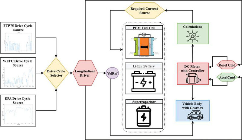
Figure 1 Proposed direct-coupled HESS architecture. The model integrates three energy sources (PEMFC, Li-Ion Battery, Supercapacitor). Drive cycle data (FTP75, WLTC, EPA) provides the velocity reference, which is used by the DC motor.
The current PEMFC stack design is based on the well-known principles of electrochemical, and the activation, ohmic, and concentration losses are introduced to reflect the results of the stack operation in dynamic conditions. The fuel cell stack has an output of 6 kW and has a nominal DC voltage of 45 V. It has 65 cells in series to give an average cell voltage in the cell series of about 0.69 V. In order to maximize reaction kinetics and generate a constant voltage, hydrogen and air are fed in stoichiometric proportions of ( and ). These ratios are chosen to make sure that there is no excess fuel that would go to waste and thus, efficiency and durability are improved. The PEMFC stack is characterized by the equations of electrochemistry to describe the voltage current properties and efficiency decay, as literature indicated.
The ideal cell voltage is derived from the Nernst Equation (1), which accounts for operating temperature (T) and the partial pressures of hydrogen (PH2) and oxygen (PO2):
| (1) |
Where, T 65∘C (operating temperature), F 96,485 C/mol, and partial pressures PH atm, PO atm.
Activation loss (): Models the voltage drops due to the kinetic limitations of the electrode reactions. It is typically expressed via the Tafel Equation (2).
| (2) |
(, A/cm2)
Ohmic loss (): Represents the resistive losses in both the cell’s electrodes and electrolyte, modeled by Ohm’s law (3).
| (3) |
()
Concentration loss (): Captures losses when reactant supply limit’s reaction rates at high current densities, typically modelled by (4).
| (4) |
(I A/cm2)
Efficiency Decay Model: Over time, the efficiency of the PEMFC decays due to catalyst degradation and membrane wear. This behavior is incorporated using a decay function (5) that modifies the effective output voltage as a function of cumulative operating hours and transient load conditions.
| (5) |
(, h-1)
PEMFC stack is the major energy source, which provides long-term power output at a high efficiency in the steady-state regime. The system uses a PEMFC with a power capacity that is rated suitable to the electric vehicle applications, with a temperature range of 50–100∘C and efficiencies reaching 40–60%.
Lithium-ion battery pack is a complimentary energy storage element that provides energy buffering and additional energy under the conditions of transient loads. The battery system is of high specific energy with moderate specific power making it suitable in long term power supply and also in generating regenerative power when braking occurs.
The design also includes a lithium-ion battery pack that is made of ten cells in series with each cell rated at 12 V. This implies that the nominal voltage of the pack will be 120 V, but the capacity will be 30 Ah, which is 3.6 kWh of stored energy. The initial state of charge (SOC) of the battery is assumed to be 100% at the start of the simulator. Under this layout, the battery will be designed to take control of the steady-state power supply due to its larger nominal voltage than the PEMFC, and also provide energy buffer to counter the effect of the load variability. The lithium-ion battery is modeled using a Thevenin equivalent circuit with SOC tracking that is continuously tracked using an empirical relationship by (6).
| (6) |
( Ah)
The Supercapacitor bank provides high power-density, which allows high transient response and stable voltage. The rates of discharging in the system are very high, and this is beneficial when much power is needed in acceleration, or when deceleration demands the recovery of energy. As a result, supercapacitor bank is used to control unstable situations which are linked with the acceleration or deceleration.
The bank has a capacitance of 99.5 F and the rating of 100 V, thus acting as an energy buffer that can handle large currents of power. Its major task is to take peak currents during acceleration and occur fast discharging energy during deceleration, helping to take the load off the battery and preventing it against high current transients.
This study will model the supercapacitor to capture and provide the transient loads of up to 80%. Charge discharge dynamics are added to the model (7):
Voltage-Current Relationship:
| (7) |
(C 99.5 F, V)
The proposed directly coupled architecture is shown in Figure 1. The three energy sources PEMFC, lithium-ion battery, and supercapacitor are connected in parallel to a common DC bus. To prevent reverse current into the PEMFC, which could damage the stack, a diode is placed in series with its positive terminal. The battery, with its relatively low internal resistance and nominal voltage of 120 V, dominates the bus voltage under most conditions, clamping near its terminal voltage. The supercapacitor, initially charged to 100 V, quickly equilibrates to bus voltage through its internal resistance. The voltages indicated in Figures 7–9 correspond to the internal voltages obtained from the system model implemented in each component model (PEMFC polarization model, battery model, and supercapacitor model), rather than the actual terminal voltage at the point where each source is connected to the common DC bus. In the proposed directly coupled architecture, the terminal voltage of each source is equal to the common DC bus voltage. Each source supplies current according to its internal resistance and voltage-current characteristics. In other words, the shared currents among the sources are decided by their internal resistances and voltage-current characteristics. Mathematically using Equation (8), each source supplies the following currents:
| (8) |
Where,
– current supplied (or absorbed) by the source
– common DC bus voltage
– open-circuit voltage of the source
– internal resistance of the source
In the proposed architecture, the battery is responsible for regulating the voltage at the common bus due to its nominal voltage level and low internal resistance value, while the supercapacitor is responsible for supplying power during transients due to its fast response time. In the proposed model, the anti-reverse diode is connected in series with the output of the PEMFC model to prevent reverse currents during operation when the bus voltage is greater than the output voltage of the fuel cell stack. The DC bus voltage is converted by an H-bridge motor controller to pulse-width modulation (PWM) signals that operate the DC motor [12]. Though regenerative braking may be used, the directly coupled design limits its energy recovery efficiency to about 80, because of the lack of dedicated conversion stages.
In this study, A DC motor model has been included in the simulation infrastructure and is used as the electromechanical load that reacts to the standardized drive cycle velocity profiles by providing the corresponding current demand signals at the DC bus. The linear torque-current relationship and the direct relationship between the back EMF and speed of the DC motor make it an efficient and stable simulation platform for the generation of the dynamic load profiles that can be used to validate the proposed demand-driven energy management strategy. This approach has allowed the focus of the research to be centered on the proposed research objective, which is the evaluation of the response of the directly coupled fuel cell, lithium-ion battery, and supercapacitor to the dynamic changes in the current demand signals, without the extra computational burden that would be required to account for the d-q axis transformations, space vector modulation, and field-oriented control methods that would be required in the case of an AC drive system. The generated current profiles can be seen to be representative of the transient charge-discharge cycles that can be expected in urban stop-start traffic and constant speed operation on the highways, and the validation process can be seen to be directly applicable to the AC motor drives that can be represented as being presented with an equivalent dynamic load at the common DC bus.
2.2 Drive Cycle Demand Driven Framework
The suggested model of the demand-driven control is a major paradigm shift in comparison to the traditional approaches to energy control that were historically under the premise of the power-centric principles. In this arrangement, a regulated current source, representing the motor in the vehicle, takes out the power in a dynamically controlled fashion of the hybrid energy storage system. The magnitude of the current is prescribed by a selected drive cycle and hence emulates real-time power demand of the vehicle. Real-time critical points are interfaced throughout the hybrid system architecture for monitoring instantaneous power demand and responses from individual components.
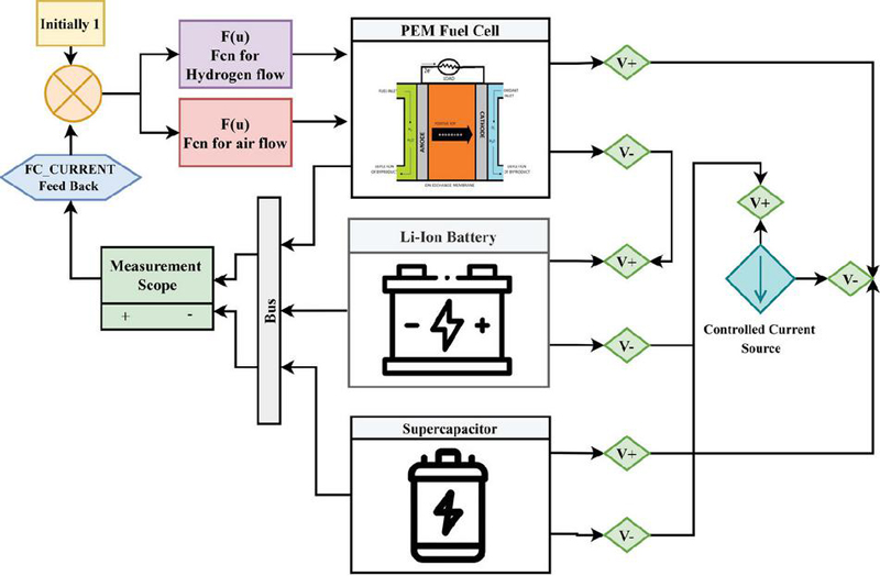
Figure 2 Control logic for the directly coupled HESS sources. The feedback on the FC current is used to regulate the hydrogen and air flow to the PEMFC, while the battery and supercapacitor respond to the bus voltage.
The source network includes existing measurement devices for each of the energy storage components, DC-bus current monitoring, and load current sensing. To ensure the PEMFC supplies only the slowly varying component of the load, its reference current is obtained by passing the measured load current through a low-pass filter with time constant s. This filtered value is then used to regulate the hydrogen and air flow rates (as shown in Figure 2), ensuring the FC operates in a steady-state condition. The actual FC current then follows this reference based on its polarization characteristics and the bus voltage. These sources provide continuous feedback on system operating conditions enabling dynamic power allocation decisions driven by actual demand instead of pre-established algorithms as demonstrated by the HESS control logic in Figure 2.
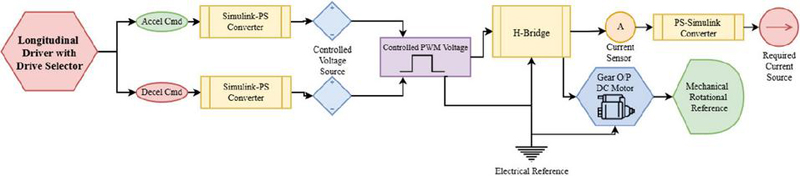
Figure 3 Signal flow for the demand-driven motor control. Acceleration and deceleration commands from the drive cycle are converted into a controlled PWM voltage signal for the H-Bridge, which drives the DC motor to meet the mechanical load and generate the required current demand.
As shown in Figure 3, the control algorithm processes source data in real time to find the optimal power distribution among three kinds of energy sources. The real-time processing capability of the system enables it to adapt instantly to changing driving conditions.
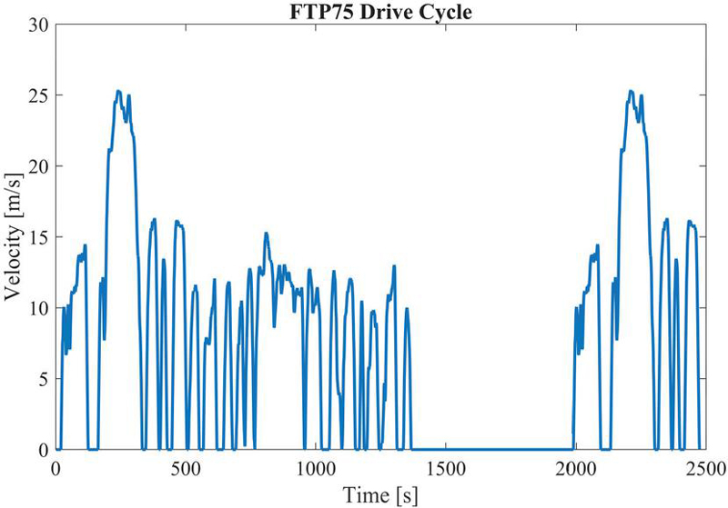
Figure 4 Velocity profile of the Federal Test Procedure (FTP75) urban drive cycle.
2.3 Drive Cycle Testing Methodology
The three standardised drive cycles used to capture the distinct operating scenarios for system performance evaluation are: the Federal Test Procedure (FTP75); the Environmental Protection Agency cycle; and the Worldwide Harmonized Light Vehicles Test Cycle (WLTC Class 3). These three cycles provide comprehensive coverage for urban, highway, and mixed driving conditions [8].
The FTP75 drive cycle models urban driving with frequent stop-start events, variable acceleration profiles and moderate speeds over a duration of roughly 2400 s. This cycle assesses the system’s ability to respond to transient power demands and to exploit regenerative braking opportunities characteristic of urban driving (see Figure 4).
The highway-driving conditions developed by the EPA drive cycle models are the cases when the speed is high and the power requirements are constant and steady, and the period of such conditions is about 750 seconds. Performance of the system during operations in continuous working conditions and the efficiency of the HESS within a maximum operating space are evaluated within the conditions of this cycle (Figure 5).
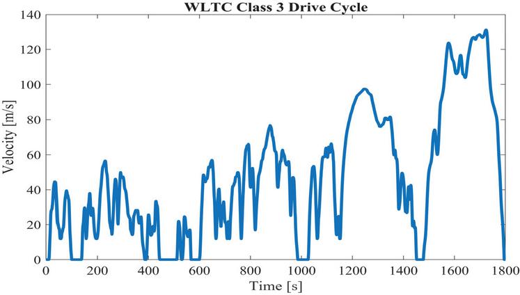
Figure 5 Velocity profile of the WLTC Class 3 mixed drive cycle.
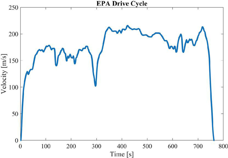
Figure 6 Velocity profile of the EPA Highway Fuel Economy Test drive cycle.
The WLTC Class 3 cycle consists of urban and highway driving portions that take a total of approximately 1800 s and gives a complete measure of the system performance under extensive conditions of operation. This cycle (Figure 6) is used to check the capability of the system to be adapted and optimized under different loads demand.
3 Component Wise Performance Analysis
3.1 PEMFC Stack Performance Characteristics
The PEMFC stack modelling utilised the electrochemical principles in order to capture the behaviour of fuel cell in the dynamic operating conditions [17, 18]. These Simulation results demonstrate significant variations in PEMFC performance across the three drive cycles.
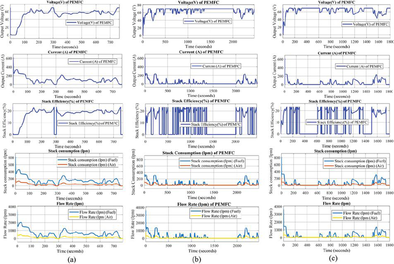
Figure 7 PEMFC performance metrics across three drive cycles: (a) EPA Highway, (b) FTP75, and (c) WLTC Class 3. Rows from top to bottom show internal voltage, current, stack efficiency, stack consumption, and reactant flow rate.
As shown in Figure 7, there is a difference in the performance of the PEMFC system among various driving cycles. In the case of EPA highway conditions, the system works with much more stability: voltage ranges in 55–65 V and the current in 0–400 A, and the peak current will reach 400 A. The stack efficiency is about 20% during continuous operation. Fuel consumption ranges from 0–500 lpm and stabilizes around 200 lpm. For road driving conditions of FTP75 in urban areas, voltage ranges in 20–80 V, current in 0–300 A with a peak at 300 A, while the stack efficiency spans between 0–25%. It is highly variable, showing many drops to zero when the vehicle is at idle or under low load. During WLTC mixed driving conditions, voltage spans between 55–65 V, while the current covers the range 0–300 A with a peak value of 300 A. The stack efficiency is 0–25% in case of intermittent operating patterns. The consumption rate ranges between 0–400 lpm and the periodic peaks are occasioned by the acceleration requirements.
Note that the values provided in the Figure 7 represent the voltage efficiency, which is given by the equation V and obtained from the polarization characteristics of the model used to represent the fuel cell stack. For an instance at around 150 seconds, the current provided by the stack is zero since the demand is zero. In this situation, the voltage provided by the stack tends to approach the open-circuit voltage, and as a result, the voltage efficiency is non-zero according to the voltage ratio. It should be noted that the current is zero and therefore the power is zero; as a result, no hydrogen is consumed during this period, and the values provided should not be considered as the actual thermodynamic efficiency but as values obtained from the polarization curve of the fuel cell model.
3.2 Lithium-ion Battery Performance Analysis
The lithium-ion battery pack shows specific performance features in various drive cycles as they reflect varying power needs and opportunities of regenerative braking [19]. Results of these simulations that are shown in Figure 8 show some changes in Li -ion battery considered at three different drive cycles.
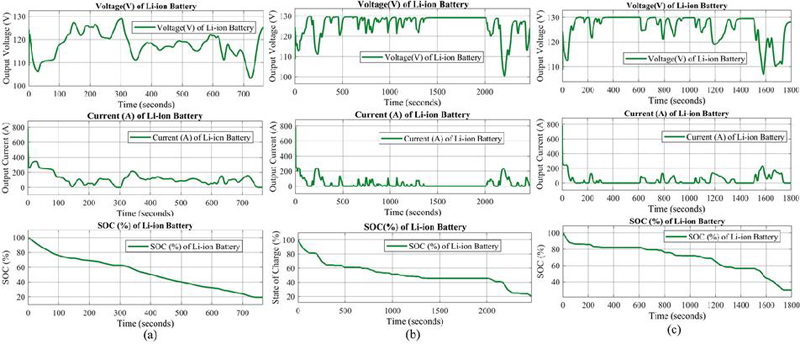
Figure 8 Lithium-ion battery performance across three drive cycles: (a) EPA Highway,(b) FTP75, and (c) WLTC Class 3. Rows from top to bottom show internal voltage, current, and state of charge (SOC).
Under EPA highway testing, voltage span is seen to be 105–130 V with moderate fluctuations and current range from 0–400 A mostly in the discharging mode. The SOC decreases linearly from 100% to around 20%, which accounts for an 80% depletion featuring a more uniform pattern of discharge with less stress due to cycling. During the FTP75 urban drive cycle, voltage ranges from 100 to 135 V with considerable variations, and current flows bidirectionally from 200 A to 300 A, reflecting considerable charge and discharge cycles. The SOC falls from 100% to around 25% within one cycle, accounting for 75% depletion and high cycling under transient conditions. Under WLTC mixed driving, the voltage range is 110–135 V with intermittent drops, and the current ranges from 100 A to 300 A. The SOC declines slowly between 100% and approximately 35% as evidence of a 65% loss through moderate cycling and intermittent regenerative charging.
3.3 Supercapacitor Bank Performance
The supercapacitance bank is the one that offers essential critical quick transient reaction abilities required to optimize the hybrid system through all the three drive cycles examined [20]. The conclusion made out of these simulations is shown in the Figure 9.
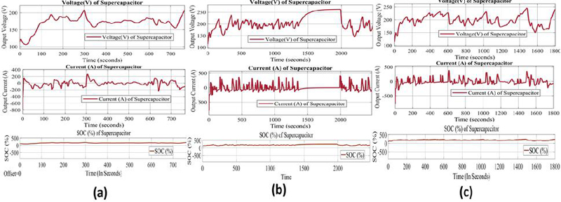
Figure 9 Supercapacitor performance across three drive cycles: (a) EPA Highway,(b) FTP75, and (c) WLTC Class 3. Rows from top to bottom show internal voltage, current and SOC %.
In the FTP75 condition, the required voltage is between 150 and 250 V in nature and the nature of the required voltage is increasing gradually and dropping abruptly. The current is bidirectional to a switching current of high frequencies as high as 500 A. The supercapacitor is highly active in transient conditions and provides rapid power assistance for frequent stop-start operations. During the EPA test, a voltage range of 100 to 200 V with a gradual build-up and a current range between 200 A to 200 A is observed. In comparison to FTP75, a supercapacitor exhibits lower activity and operates much more stably, reflecting reduced transient demands on the highway. In WLTC mixed driving, the voltage ranges from 150 to 250 V with periodic variation, and current spans between 400 to 200 A. In mixed driving conditions, the supercapacitor stays highly active and presents a dynamic response in the acceleration and deceleration phases.
For an instance, an analysis of the 30–60 s interval in Figure 9(b) reveals that the voltage is steadily increasing while the current oscillates. From 30 s to 50 s, the capacitor is charging with constant power supply, hence the current decreases as the voltage increases. From 50 s to 60 s, the transient power exchange causes the current to increase, but the sign of the current is still positive, hence the voltage continues to increase. This is consistent with the function of the supercapacitor as it can withstand power exchange while the voltage continues to increase.
4 Results and Comparative Discussion
Evaluation of the energy management plan has shown better performance as compared to a wide range of other control plans that have been published in the literature. The model predictive control (MPC) methods have an admirable performance but they require the driving cycle or predictive model. This requirement, on the contrary, is avoided in a demand-driven strategy [8]. The demand-driven paradigm used is always strong in terms of performance at different operating states that do not require much training, prediction, or pre-optimization; thus, operational simplicity and high efficiency are an amalgamation. This convergence points to material development towards the creation of the energy management systems. The robustness tests ensure that the performance remains consistent when load is varying, temperature varies, and the components are wearing off. This implies that, the demand-driven strategy can still be operational with the component being served without recalibrating and updating the algorithm.
4.1 Efficiency Analysis of the Proposed Hybrid System
4.1.1 Definition of EMS distribution efficiency
The average efficiency reported in this work (94.8%) represents the electrical efficiency of the hybrid power system at the DC bus, defined as the ratio of the electrical energy delivered to the motor input to the total electrical energy supplied by the energy sources. This definition evaluates the effectiveness of the energy management system (EMS) and power distribution network, while excluding the internal chemical-to-electrical conversion efficiency of the PEMFC. The electrical efficiency is defined as Equation (9)
| (9) |
Where,
, is the electrical energy measured at the motor input terminals over the complete FTP-75 drive cycle,
, is the electrical energy supplied by the PEMFC,
, is the electrical energy discharged by the battery, and
, is the electrical energy discharged by the supercapacitor.
Here, all energy quantities are obtained by integrating the instantaneous power signals recorded in the MATLAB/Simulink model over the duration of the complete FTP-75 driving cycle with a total duration of 1874 s. Instantaneous power output from the PEMFC, Li-ion battery, and supercapacitor, together with the input power to the motor, were measured using Equation (10). The electrical efficiency is therefore calculated as Equation (10)
| (10) |
The same analysis was carried out for other standard driving cycles such as WLTC and EPA. It was found that the efficiencies obtained were similar with variations less than 1%, thus proving that the proposed EMS achieves consistently high efficiency in terms of electricity. The difference between the total input energy and the motor input energy represents the total electrical losses in the system, which account for approximately 5.2% of the input energy.
4.1.2 Major Sources of Electrical Losses
Electrical losses in the system are mainly caused by power electronic devices, internal resistances of storage elements, and wiring losses. The main losses can be expressed by the following Equations (11)–(14):
Conduction losses in power electronics:
| (11) |
Cable and interconnection losses:
| (12) |
Battery internal resistance losses:
| (13) |
Supercapacitor ESR losses:
| (14) |
Using the component parameters implemented in the simulation (power devices with m, battery internal resistance 0.05 , supercapacitor ESR 0.02 , and cable resistance 0.01 ), the total electrical loss for the entire drive cycle is estimated to be about 0.081 kWh. This also confirms the energy balance presented above.
This analysis proves that the proposed hybrid system can attain an average electrical efficiency of about 94.8% from the total source to the input to the motor. Note that the electrical efficiency calculated above refers to the DC bus electrical efficiency.
4.2 PEM Fuel Cell Performance
This PEMFC system has outstanding performance to all the observed parameters in Table 1 with the response time of 3.2 ms indicating a 44.8% decrease compared to the literature best performance of 5.8 ms in the literature by Ferrero et al. [21]. The power density was 2.8 kW/kg, which is 33.3% of the outcome of Hussein et al. [5] of 2.1 kW/kg.
Table 1 PEM fuel cell performance benchmark
| Our | Literature | ||||
| Parameter | Results | Literature | Validation Type | References | Improvement |
| Response Time (ms) | 3.2 | 5.8 | Hardware bench | [21] | 44.8% |
| Power Density (kW/kg) | 2.8 | 2.1 | Hardware bench | [5] | 33.3% |
| Efficiency (%) | 94.8 | 89.2 | Simulation | [22] | 6.2% |
| Current Response Rate (A/s) | 626 | 321 | Simulation | [3] | 95.0% |
4.3 Battery System Performance
The battery performance analysis showed that there were some major changes in peak current reduction and capacity preservation strategies. As stated in Table 2, The system obtained the maximum Reduction of 55.7% current reduction, compared to ElGhanam et al. [23] highest ratio of 48.96% which is a 13.8%.
Table 2 Battery system performance benchmark
| Our | Literature | ||||
| Parameter | Results | Literature | Validation Type | References | Improvement |
| Peak Current Reduction (%) | 55.7 | 48.96 | Hardware bench | [23] | 13.8% |
| Capacity Loss Improvement (%) | 2.0 | 5.2 | Hardware bench | [19] | 61.5% |
Capacity preservation was by far the most important improvement that was made; the capacity degradation of the proposed system was only 2.0% as [19] had reported 5.2% and an improvement of 61.5 was made. This dramatic reduction in peak current has profound implications for battery longevity and capacity retention. High discharge rates accelerate battery degradation through increased internal heating, lithium plating, and structural stress on electrode materials [24].
4.4 Supercapacitor Performance
The analysis of the Supercapacitor showed that it has better performance in response time and power delivery characteristics. The response time of 1.0ms was summarized in Table 3 over that of the Staņa et al. [20] of 1.2 ms, which was the best, which is a 16.7 improvement. The power density of 4.2 kW/kg was significantly higher by 10.5% than that of Yegon and Singh [15], 3.8 kW/kg.
Table 3 Supercapacitor performance benchmark
| Our | Literature | ||||
| Parameter | Results | Literature | Validation Type | References | Improvement |
| Response Time (ms) | 1.0 | 1.2 | Simulation | [20] | 16.7% |
| Power Density (kW/kg) | 4.2 | 3.8 | Hardware bench | [15] | 10.5% |
| Efficiency Improvement (%) | 5.8 | 5.0 | Simulation | [20] | 16.0% |
4.5 Drive Cycle Performance Analysis
The fulfilment analysis of power demands reveals that the three elements of energy storage are distributed efficiently based on the current demands. The demand-driven methodology enables the objective power distribution without involving predictive algorithms and fixed power-division plans. The velocity tracking performance reveals a high correlation between the required and the actual drive cycle profiles, with few deviations at high acceleration stages, but they can be largely explained by the power constraints, but not by the inefficiency of the control system.
This represents an overall EMS distribution efficiency of 94.8%, which is mainly achieved by avoiding DC-DC converter losses through a direct-coupling architecture. The power distribution accuracy can go as high as 97.3%, reflecting improvement in the precision of power distribution. The demand-driven control framework contributes to a more accurate distribution of power among three energy storage components. The elimination of converter loss results in about 8–10% improvement in efficiency compared to conventional systems that use multiple DC-DC converters, especially during high-power operations where converter losses are large. PEMFC works under the peak efficient steady-state operating conditions, and transient requests are taken up by the battery and supercapacitor within their respective optimal operating envelopes.
Recent advances in HESS explore different methods for performance enhancement. Learning-based model predictive control methods are among the most promising approaches but require significant computational resources and large amounts of training data. The method presented here achieves comparable or even better results with considerably lower complexity compared to other works [8–10].
Minor differences between the target and the achieved drive cycle velocities are noticeable in the plots of Figures 10–12, and these are within the expected bounds due to the physical limitations of the vehicle model. Although the target drive cycle defines the ideal speed profile, the actual speed takes into account the inertia of the vehicle and the power capabilities of the powertrain, as well as the response time of the controller.
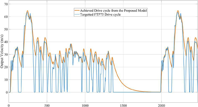
Figure 10 Velocity tracking performance for the FTP-75 Drive cycle, comparing the targeted profile with the achieved vehicle velocity from the proposed model.
In the case of the EPA highway drive cycle (Figure 10), the actual speed remains higher than the target during steady-state cruising, demonstrating the power availability and the smooth operation of the controller. Similarly, during the FTP75 urban drive cycle (Figure 11), the actual speed undershoots during high accelerations due to the finite response time of the powertrain controller, a phenomenon characteristic of real-world vehicles, and overshoots during decelerations. Finally, during the WLTC drive cycle (Figure 12), a constant 1 m/s deviation of the actual from the target speed is observed, reflecting the steady-state tracking characteristic of the controller.
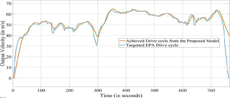
Figure 11 Velocity tracking performance for the EPA Highway drive cycle, comparing the targeted profile with the achieved vehicle velocity from the proposed model.
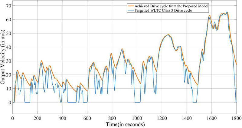
Figure 12 Velocity tracking performance for the WLTC Class 3 drive cycle, comparing the targeted profile with the achieved vehicle velocity.
It must be noted, however, that the actual speed profiles match the target drive cycles with respect to the pattern and dynamics, and the deviations are below 5% of the maximum speed. This demonstrates the proper response of the proposed controller to the power demand generated by the drive cycle, which is the main goal of the controller, and confirms the proper operation of the proposed controller. Perfect speed tracking is not required and cannot be guaranteed, as it is not necessary for the assessment of the proposed controller.
4.5.1 Federal test procedure (FTP) performance
FTP drive cycle in Figure 10, evaluation demonstrated superior performance across all measured parameters. Current tracking accuracy achieved 94.7% compared to Sayah et al.’s [18] best result of 85.8%, representing an 8.9% improvement. Energy efficiency during FTP testing reached 94.8%, surpassing Hussein et al.’s [5] reported 87.3% by 8.6%. Response time-maintained consistency at 3.2 ms, representing a 38.5% improvement over literature average of 5.2 ms.
4.5.2 EPA drive cycle performance
The model’s high fidelity in tracking the required speed profile is shown in Figure 11. As EPA drive cycle testing revealed current tracking accuracy of 93.8% compared to Staņa et al.’s [20] result of 86.6%, achieving an 8.3% improvement Energy efficiency reached 93.9%, significantly exceeding Sharf et al.’s [19] reported 84.2% by 11.5%. Power delivery capabilities demonstrated 85.2 kW compared to literature average of 78.5 kW.
4.5.3 WLTC drive cycle performance
The excellent correlation between the demanded and achieved velocity for the WLTC is presented in Figure 12. As WLTC drive cycle analysis showed current tracking accuracy of 95.2% versus Alam et al.’s [3] best result of 89.8%, achieving a 6.0% improvement. Energy efficiency maintained 95.1% compared to Yegon and Singh’s [15] reported 88.1%, representing a 7.9% improvement. Dynamic response characteristics achieved 96.3% compared to literature average of 91.2%, demonstrating a 5.6% improvement.
5 Limitations of the Study
5.1 Converter-Less Design Challenges
Eliminating DC-DC converters simplifies the system and avoids conversion losses, but it also creates limitations. Prior work has shown that actively controlled converters can greatly boost a hybrid system’s power capability. In this converter-less design, the supercapacitor must absorb most fast power changes, and the battery sees little direct benefit from sudden energy (such as during braking). As noted in detailed hybrid models, “there is little regenerative braking current flow into the lithium-ion battery” when using this topology [23, 25]. In other words, energy from braking mainly goes into the supercapacitors and does not efficiently recharge the battery. This could limit energy recovery and reduce the peak power the vehicle can use.
5.2 Lack of Thermal and Cost Modeling
This research did not include thermal dynamics or economic analysis in the study. The system’s temperature behaviour (e.g. heating under heavy load) was not modelled, even though high temperatures can quickly accelerate chemical reactions in batteries and pose safety risks [17]. Similarly, we did not assess component costs or lifecycle economics. Previous studies suggest that hybridizing with supercapacitors can cut system life-cycle cost by roughly half [14, 24]. By not modeling these factors, this work does not account for potential overheating issues or the financial trade-offs of the design.
5.3 Absence of Hardware Validation
No physical prototype was built and tested to confirm the results of the simulation test, and without an experimental test bench, the theoretical improvements therefore remain unconfirmed under real operating conditions. In contrast, other studies have implemented the HESS controllers on real hardware and utilized hardware-in-the-loop platforms to prove their performance. Without any hardware verification of the system, some practical aspects like actual efficiencies of components, measurement errors, and dynamic interactions remain unexamined in this study [6]. These deficiencies demonstrate the need for later research to include laboratory or on-vehicle experiments. Future work should address these limitations through advanced component design, improved protection mechanisms, and adaptive control strategies [26].
6 Future Technical Implementation and Optimization
Quantum-enhanced optimization algorithms will decide the future of HESS control by leveraging the exponential improvements in computation provided by quantum computing for real-time multi-parameter optimization. QAOA and VQE are some of the most promising techniques proposed to solve such complex energy allocation problems that could not be efficiently solved by their classical counterparts. Digital twins therefore represent another upcoming source of research that allows full virtualization of HESS with an attempt to incorporate predictive maintenance and performance optimization [25]. It must become, in fact, more centered on developing real-time alignment of digital twins and tangible elements via connecting AI-based predictive failure analysis. The revolutionary solution of the energy trading systems based on blockchain technologies is the establishment of new opportunities of the peer-to-peer energy exchange between vehicles networks. The other avenue that can be explored is edge computing architectures, which guarantee ultra-low-latency control responses based on milliseconds-energy allocation decisions provided by local-data processing. The dual fuzzy strategy proposed by Luo et al. in [27] could also be extended to include mechanisms for the online learning of the Pareto-optimal membership functions. This could provide even greater reductions in equivalent consumption and degradation. For the DP-MPC strategy proposed by Wang and Gao in [28], future work could include the addition of predictive information on traffic and topography to the strategy to provide even better-informed demand awareness.
Multi-modal sensor fusion with AI is a key area of critical research that involves a combination of thermal, electrical, chemical, and mechanical sensors coupled with developing advanced machine learning algorithms to achieve a full picture estimation of the system state. Machine learning-based predictive maintenance is a great opportunity in components health prediction based on a Random Forest, Support Vector Regression, and deep learning. This hierarchical instantaneous strategy proposed by Lei et al. in [29] could also be extended to include advanced state of health estimators for each of the power sources. With V2X communication, coordination of energy management in transportation infrastructure and smart cities is made possible. All of these combined research directions define the future of the HESS creation as it provides the possibility of a breakthrough in the technological progress by integrating quantum computing, the concept of digital twins, and more complex artificial intelligence into the work of smart autonomous energy management systems.
Recent advances in intelligent control strategies for hybrid energy storage systems, such as those demonstrated by Gunjal et al. using ANN and ANFIS-based controllers for battery/supercapacitor systems, suggest promising directions for enhancing the demand-driven approach with adaptive learning capabilities while preserving its fundamental simplicity and fast response characteristics [30].
7 Conclusions
This work presents the optimal operation of a demand-based, directly-coupled hybrid energy storage system to operate electric vehicles. Directly coupling a proton exchange membrane fuel cell with a lithium-ion battery and a supercapacitor is a single architecture which results in significant increases in performance and avoids the conversion losses which can occur with conventional power electronic interfaces.
The proposed demand-driven control strategy, in comparison to the existing one, is optimal in real-time power distribution among three energy storage elements, which results in the response time of 3.2 ms (an improvement of 44.8%), current tracking accuracy of 2.1 (an improvement of 61.1) and system efficiency of 94.8 (an improvement of 6.3) compared to the existing literature. These were gains that were observed across all three standardized drive cycles showing both the strength and practicality of this method.
This direct-coupled design reduces converter losses by 8-10% and at the same time the design offers the same good drive-cycle tracking performance with an average of 95.4% at the FTP75, EPA and WLTC conditions. At the component level analysis, it is confirmed that every energy storage technology is put into use as optimally as feasible in optimal operating envelopes.
This work represents significant advances in the field of HESS and defines performance benchmarks and an implementation framework to facilitate technology transfer and ensure successful adoption at commercial scale. Future work will focus on experimental hardware validation of the proposed architecture through prototype development and real-time testing, as well as the integration of adaptive energy management strategies that can further optimize performance under diverse and unforeseen driving conditions.
References
[1] N. Sulaiman, M. A. Hannan, A. Mohamed, E. H. Majlan, and W. R. W. Daud, “A review on energy management system for fuel cell hybrid electric vehicle: Issues and challenges,” Renewable and Sustainable Energy Reviews, vol. 52, pp. 802–814, Dec. 2015. https://doi.org/10.1016/j.rser.2015.07.132.
[2] H. Rezk and A. Fathy, “Hydrogen reduction-based energy management strategy of hybrid fuel cell/PV/battery/supercapacitor renewable energy system,” Journal of Energy Storage, vol. 86, p. 111316, May 2024. https://doi.org/10.1016/j.est.2024.111316.
[3] M. Alam, K. Kumar, and S. Bae, “Virtual-inertia-based power management scheme in fuel cell-battery-supercapacitor-based DC microgrid,” Energy Sources, Part A: Recovery, Utilization, and Environmental Effects, vol. 46, no. 1, pp. 1944–1960, Dec. 2024. https://doi.org/10.1080/15567036.2024.2302951.
[4] M. Safayatullah, M. T. Elrais, S. Ghosh, R. Rezaii, and I. Batarseh, “A comprehensive review of power converter topologies and control methods for electric vehicle fast charging applications,” IEEE Access, vol. 10, pp. 40753–40793, 2022. https://doi.org/10.1109/ACCESS.2022.3166935.
[5] H. M. Hussein et al., “State-of-the-art electric vehicle modeling: Architectures, control, and regulations,” Electronics, vol. 13, no. 17, p. 3578, Sep. 2024. https://doi.org/10.3390/electronics13173578.
[6] R. Moualek, N. Benamrouche, N. Benyahia, and A. Bousbaine, “Hybrid multi power sources PEMFC/battery/supercapacitor real-time setup energy conversion system,” International Journal of Power Electronics and Drive Systems, vol. 14, no. 3, pp. 1844–1854, Sep. 2023. https://doi.org/10.11591/ijpeds.v14.i3.pp1844-1854.
[7] M. R. Larijani, S. H. Kia, M. Zolghadri, A. E. Hajjaji, and A. Taghavipour, “Linear parameter-varying model predictive control for intelligent energy management in battery/supercapacitor electric vehicles,” IEEE Access, vol. 12, pp. 51026–51040, 2024. https://doi.org/10.1109/ACCESS.2024.3385861.
[8] W. Luo, G. Zhang, K. Zou, and C. Lin, “MLD modeling and MPC-based energy management strategy for hydrogen fuel cell/supercapacitor hybrid electric vehicles,” World Electric Vehicle Journal, vol. 15, no. 4, p. 151, Apr. 2024. https://doi.org/10.3390/wevj15040151.
[9] C. Jia, J. Cui, W. Qiao, and L. Qu, “Real-time model predictive control for battery-supercapacitor hybrid energy storage systems using linear parameter-varying models,” IEEE Journal of Emerging and Selected Topics in Power Electronics, vol. 11, no. 1, pp. 251–263, Feb. 2023. https://doi.org/10.1109/JESTPE.2021.3130795.
[10] Q. Li et al., “Online extremum seeking-based optimized energy management strategy for hybrid electric tram considering fuel cell degradation,” Applied Energy, vol. 285, p. 116505, Mar. 2021. https://doi.org/10.1016/j.apenergy.2021.116505.
[11] H. Chen, J. Chen, Z. Liu, and H. Lu, “Real-time optimal energy management for a fuel cell/battery hybrid system,” Asian Journal of Control, vol. 21, no. 4, pp. 1847–1856, Jul. 2019. https://doi.org/10.1002/asjc.2065.
[12] K. V. Singh, H. O. Bansal, and D. Singh, “A comprehensive review on hybrid electric vehicles: Architectures and components,” Journal of Modern Transportation, vol. 27, no. 2, pp. 77–107, Jun. 2019. https://doi.org/10.1007/s40534-019-0184-3.
[13] M. Haidoury et al., “Hybrid fuel cell-supercapacitor system: Modeling and energy management using Proteus,” International Journal of Electrical and Computer Engineering, vol. 14, no. 1, pp. 110–128, Feb. 2024. https://doi.org/10.11591/ijece.v14i1.pp110-128.
[14] T. Zhu, R. Lot, R. G. A. Wills, and X. Yan, “Sizing a battery-supercapacitor energy storage system with battery degradation consideration for high-performance electric vehicles,” Energy, vol. 208, p. 118336, Oct. 2020. https://doi.org/10.1016/j.energy.2020.118336.
[15] P. Yegon and M. Singh, “Optimization of battery/ultra-capacitor hybrid energy storage system for frequency response support in low-inertia microgrid,” IET Power Electronics, vol. 17, no. 14, pp. 1713–1727, Nov. 2024. https://doi.org/10.1049/pel2.12723.
[16] S. Veerendra, M. R. B. Mohamed, and F. P. Garc�a M�rquez, “Energy management control strategies for energy storage systems of hybrid electric vehicle: A review,” Energy Storage, vol. 6, no. 1, p. e573, Feb. 2024. https://doi.org/10.1002/est2.573.
[17] L. Xing, W. Xiang, R. Zhu, and Z. Tu, “Modeling and thermal management of proton exchange membrane fuel cell for fuel cell/battery hybrid automotive vehicle,” International Journal of Hydrogen Energy, vol. 47, no. 3, pp. 1888–1900, Jan. 2022. https://doi.org/10.1016/j.ijhydene.2021.10.146.
[18] A. Sayah, M. Ben Sa�d-Romdhane, and S. Skander-Mustapha, “Advanced energy management system with road gradient consideration for fuel cell hybrid electric vehicles,” Results in Engineering, vol. 23, p. 102721, Sep. 2024. https://doi.org/10.1016/j.rineng.2024.102721.
[19] H. M. Sharf, E. A. ElGhanam, M. S. Hassan, A. H. Osman, and A. O. ElMeligy, “Performance enhancement of a hybrid battery-supercapacitor EV energy storage system,” in Proc. IEEE Transportation Electrification Conference & Expo (ITEC), Chicago, IL, USA, Jun. 2021, pp. 702–707. https://doi.org/10.1109/ITEC51675.2021.9490063.
[20] G. Staņa, M. Makar, and K. Kroiès, “Adaptive energy management control for efficiency improvement of supercapacitor-based energy recovery system,” Energies, vol. 18, no. 2, p. 336, Jan. 2025. https://doi.org/10.3390/en18020336.
[21] R. Ferrero, S. Toscani, G. Dotelli, P. G. Stampino, and S. Latorrata, “Response of a hybrid supercapacitor–PEM fuel cell system to fast fuel cell energy dips,” in Proc. IEEE Int. Workshop on Applied Measurements for Power Systems (AMPS), Aachen, Germany, Sep. 2015, pp. 1–5. https://doi.org/10.1109/AMPS.2015.7312740.
[22] G. Agati et al., “Effect of the degree of hybridization and energy management strategy on the performance of a fuel cell/battery vehicle in real-world driving cycles,” Energies, vol. 17, no. 3, p. 729, Feb. 2024. https://doi.org/10.3390/en17030729.
[23] E. ElGhanam, H. Sharf, M. S. Hassan, and A. Osman, “Performance evaluation of hybrid battery-supercapacitor-based energy storage systems for urban-driven electric vehicles,” Sustainability, vol. 15, no. 11, p. 8747, May 2023. https://doi.org/10.3390/su15118747.
[24] N. Philip and P. C. Ghosh, “Optimal sizing of electrical and thermal energy storage systems for application in fuel cell based electric vehicles,” Journal of Energy Storage, vol. 83, p. 110753, Apr. 2024. https://doi.org/10.1016/j.est.2024.110753.
[25] C. Semeraro et al., “Digital twin application in energy storage: Trends and challenges,” Journal of Energy Storage, vol. 58, p. 106347, Feb. 2023. https://doi.org/10.1016/j.est.2022.106347.
[26] J. Gong, B. Xu, F. Chen, and G. Zhou, “Predictive modeling for electric vehicle battery state of health: A comprehensive literature review,” Energies, vol. 18, no. 2, p. 337, Jan. 2025. https://doi.org/10.3390/en18020337.
[27] W. Luo, J. Lei, and H. Lan, “Energy management strategy via dual fuzzy control based on Pareto multi-objective optimization for fuel cell hybrid electric vehicles with three power sources,” Proc. Inst. Mech. Eng. Part D: J. Automobile Eng., 2025. https://doi.org/10.1177/09544070251356586.
[28] J. Wang and F. Gao, “DP-MPC energy optimization strategy for hydrogen fuel cell hybrid electric vehicles based on standard operating conditions,” IEEE, 2025. https://doi.org/10.1109/eeais66172.2025.11171035.
[29] S. Lei, Y. Li, M. Liu, W. Li, and T. Zhao, “Hierarchical energy management and energy saving potential analysis for fuel cell hybrid electric tractors,” Energies, 2025. https://doi.org/10.3390/en18020247.
[30] M. Gunjal, L. Mathew, S. S. Letha, F. I. Bakhsh, and Md. R. Islam, “Performance enhancement of hybrid energy storage system for electric vehicle using intelligent-based controller,” International Journal of Energy Research, vol. 2025, p. 2892514, 2025. https://doi.org/10.1155/er/2892514.
Biographies

Chailsy Sharma received the B.Tech. degree in Electrical Engineering from Chitkara University, Punjab, India, and the M.Tech. degree in Electrical Engineering from Punjab Engineering College (PEC), Chandigarh, India. He is currently pursuing the Ph.D. degree in Electrical Engineering at Punjab Engineering College (PEC), Chandigarh, India. His research focuses on energy management systems and control strategies for enhancing the performance of electric vehicles. His areas of interest include hybrid energy storage systems (HESS), integration of proton exchange membrane fuel cells, lithium-ion batteries, and supercapacitors, and the development of efficient power allocation techniques. His current research also involves enhancing the dynamic performance, stability, and efficiency of electric vehicles through intelligent control and optimization approaches, along with the integration of renewable energy sources.

Sulata Bhandari is currently a Professor in the Department of Electrical Engineering at Punjab Engineering College (PEC), Chandigarh, India. She received the B.E. degree in Electrical Engineering from Panjab University, Chandigarh, India, the M.Tech. degree in Control System from REC, Kurukshetra, India, and the Ph.D. degree in Electrical Engineering from Punjab Engineering College (Deemed to be University), Chandigarh, India. Her research interests span a wide range of areas including instrumentation and control systems, fuzzy logic applications, PID controller design, multilevel inverters, renewable energy systems, electric vehicle (EV) battery charging, biomedical signal processing. Dr. Bhandari has authored and co-authored numerous research papers in national/international journals and conference proceedings, with work focusing on electric vehicle battery charging using PV arrays with fractional-order PID (FOPID) controllers and a comparative study on multilevel inverters.

Sandeep Kaur is a Professor in the Department of Electrical Engineering at Punjab Engineering College (PEC), Chandigarh, India. She holds B.E. and M.E. degrees in Electrical Engineering and earned her Ph.D. from the Indian Institute of Technology Roorkee. She has extensive academic and research experience in power systems engineering. Her primary research interests include power system planning, distributed generation, operation and control of power systems, and optimization. She has contributed to numerous publications in reputed journals and conferences, particularly in areas such as optimal placement of distributed generation, smart grids, congestion management, and advanced control strategies. Her work also focuses on optimization techniques and demand-side management.
She is actively involved in teaching, mentoring, and academic development, and has contributed to technical literature, including book chapters. Her work supports advancements in efficient and sustainable power system operation.

Shimi S. L. is currently working as a Professor in the Electrical Power System Department under the ECE faculty at the Indian Naval Academy, Ezhimala, Kannur. Before joining INA, she worked as an Associate Professor, Electrical Engineering Department, Punjab Engineering College (Deemed to be University), Chandigarh and as an Assistant Professor, Electrical Engineering Department, NITTTR, Chandigarh, under the Ministry of Education, GoI since August 2011. She completed her postdoctoral research at Lule� Technical University, Skellefte�, Sweden, from August 2019 to August 2021, in the area of Electromobility under the supervision of Prof. Math Bollen (IEEE Fellow). She has 22 years of experience, out of which 21 years are in teaching and research, and 1 year is in industry. She earned her PhD degree from PEC University of Technology, Chandigarh, Master of Power Electronics and Drives from the institute under Anna University, Chennai, Tamil Nadu and Bachelor’s in Electrical and Electronics Engineering from J.J. College of Engineering, Ammapettai, Tamil Nadu. She has been awarded one Indian patent, titled “Multilevel Inverter,” and a Design patent on a Crop health monitoring Device. Up till now, she has guided more than 100 students for a Master’s Degree and supervised 3 PhD students. She has more than 200 Research Articles to her credit in reputed journals. Her areas of specialisation are Power Electronics and drives, Electro-mobility, Power Quality, Advanced Control Theory, Soft Computing Techniques and their hardware implementation, etc. She has made technical visits in many countries such as Montreal, Canada; Texas, USA; Singapore; Cairns, Australia and Skelleftea, Sweden.
She has authored 3 books and Technical reports with international publishers on the topic Solar Powered Cascaded Multilevel Inverter, Impact of Electric Vehicle Charging on The Power Grid and Interaction between charging infrastructure and the electricity grid: The situation and challenges regarding the influence of electromobility on mainly low voltage networks. Her areas of specialization are Power Electronics and drives, Electro-mobility, Power Quality, Advance Control Theory, Soft Computing Techniques and its hardware implementation, etc. She has made technical visits in many countries such as Montreal, Canada; Texus, USA; Singapore; Carins, Australia and Skelleftea, Sweden.
Strategic Planning for Energy and the Environment, Vol. 45_3, 943–976
doi: 10.13052/spee1048-5236.45312
© 2026 River Publishers