Transient Voltage Control Strategy for Large-Scale Photovoltaic Access to Sending-End System
Yu Wu1,*, Chuang Liu1, Dongbo Guo2, Ruifeng Li1 and Wuyi Zhou1
1School of Electrical Engineering, Northeast Electric Power University, Jilin, Jilin, 132012, China
2Tsinghua University, Beijing, 100084, China
E-mail: 2202300313@neepu.edu.cn
∗Corresponding Author
Received 05 March 2026; Accepted 15 March 2026
Abstract
This paper tackles the challenge of insufficient transient voltage support capability in sending-end systems following large-scale photovoltaic (PV) integration. A novel two-tier hierarchical control strategy is proposed, specifically directed toward the grid-connected point and the photovoltaic power station collection point. The grid-connected point control layer establishes a transient voltage security assessment index based on the voltage recovery boundary. It also presents an optimization method for SVC installation location, followed by a capacity optimization model that balances voltage security and investment costs, solved using the Dung Beetle algorithm. The collection point control layer improves transient voltage recovery by dynamically quantifying the distance to the recovery boundary and integrating it with fuzzy adaptive reactive power control for PV stations. Validation of the method’s efficacy is achieved via simulations conducted on an augmented Nordic test system.
Keywords: Transient voltage control, condenser, dung beetle optimization algorithm, dynamic reactive power compensation optimization, fuzzy adaptive control.
1 Introduction
Against the strategic backdrop of accelerating the low-carbon transition in the global energy sector, wind and solar power – core forms of renewable energy – have emerged as a crucial pathway for upgrading the worldwide power system, driven by their large-scale and sustained grid integration [1–4]. Amidst this shift, the share of renewable energy integrated into the sending-end grid (a primary obligation of the power output terminal) has grown substantially. Previously, many fossil fuel-reliant thermal units were replaced by renewable energy equipment, resulting in a continuous drop in the sending-end grid’s short-circuit ratio and exhibiting traits of a weak sending-end network [5]. Under such circumstances, the voltage regulation capacity of the sending-end grid is compromised, leaving these grids vulnerable to severe transient voltage security threats during fault events. Such fault events are frequently exacerbated by the inherent vulnerabilities of traditional grid infrastructure to operational uncertainties and resilience challenges [6], as well as the increasingly complex load dynamics and voltage deviation risks under high renewable penetration [7], making advanced condition monitoring and data-driven intelligent fault feature extraction [8] essential prerequisites for pre-empting system instability. On one hand, owing to the limited anti-disturbance capability and restricted overcurrent tolerance of renewable generators in the sending-end grid, the system frequently fails to maintain safe transient voltage ride-through post-fault, potentially triggering grid disconnection incidents [9, 10]. Such disconnections are highly prone to triggering severe grid safety incidents, posing significant harm to the stable operation of the entire power system.
Compared with the synchronous condenser, the SVC/STATCOM device has obvious shortcomings in reactive power response [11, 12]. Its reactive power response ability is weak, and the reactive power response has time delay characteristics. In some cases, these defects may even lead to more serious transient overvoltage security problems. As a rotating synchronous component, the synchronous condenser shows a strong ability to quickly swallow reactive power in the key stage of fault occurrence and removal by virtue of its electromagnetic transient instantaneous reactive power response characteristics, so as to have a good transient overvoltage suppression effect. Therefore, the reasonable optimization of its access location and configuration capacity has become an important issue. Aiming at the problem of insufficient voltage support strength for renewable energy access to the power grid, Reference [13] introduced a condenser site selection optimization method centered on maximizing GSCR improvement but omitted capacity optimization for the condenser. For References [14–16], a condenser configuration optimization model was developed where the short-circuit ratio requirements of renewable power stations served as primary constraints. Reference [17] investigated the optimal sizing of synchronous condensers for subsynchronous oscillation suppression, with the key constraint being that the system’s impedance ratio matrix in typical operating scenarios meets the generalized Nyquist criterion. In References [18, 19], the maintenance of grid node voltages within an acceptable range throughout the transient phase was adopted as the primary constraint for synchronous condenser optimal configuration.
Enhancing the control system facilitates accelerated transient voltage recovery in the system. Reference [20] proposes a transient voltage load shedding strategy based on fuzzy adaptive control. Meanwhile, Reference [21] established an emergency control framework grounded in Safety Reinforcement Learning (SRL) to mitigate transient voltage instability. Aiming at the problem of voltage delay recovery after fault, Reference [22] enhanced transient stability by combining edge graph convolutional network with reinforcement learning. Reference [23] proposed a new derivative-free DRL algorithm of PARS, and carried out voltage stability control of power system by load shedding. However, the above research objects are all conventional AC power grids, and the access of renewable energy stations is not considered. Existing emergency control strategies often overlook the specific regulation capabilities of renewable energy stations. For instance, Reference [24] developed a meta-learning-based approach for controlling transient voltage via renewable energy grid-connection. Reference [25] examined how crowbar circuits and various fault current limiters enhance the Low Voltage Ride-Through capability in photovoltaic systems, thereby supporting grid-connected voltage stability. Meanwhile, Reference [26] implemented a fuzzy adaptive reactive power control method for hybrid wind-solar-thermal systems to meet precise voltage recovery demands. A recognized limitation, however, is the inherent insufficiency of short-term reactive power support from renewable stations themselves. Consequently, future work must explore how to augment the transient voltage dip control strategies for these stations by leveraging the support capacity of dedicated reactive power compensation devices.
2 Transient Voltage Stability Control Framework of Sending-End System
‘Real-time decision-making, real-time matching’ [27] not only has high fault tolerance for inaccurate system models and parameters, but also can match the transient process after fault in real time. According to the current national standard, wind turbines/photovoltaic inverters are more reactive power resources than SVG and other equipment [28] In the renewable energy station, the unit usually receives the instructions issued for the station and then executes. The GOOSE communication protocol can greatly reduce the communication delay. At this time, the fastest reactive power response time reported can be compared with SVG, which is about 2327 ms [29].
To maximize the utilization of renewable energy’s millisecond-level reactive power regulation capacity, the intelligent fast-acting power control device – deployed at a renewable energy station’s grid-connection point – can be effectively employed. By utilizing the information linkage across all system levels, this approach enables the realization of a complete transient voltage regulation process. This integrated process encompasses main station voltage perception, reactive power strategy computation, timely instruction issuance, high-speed optical fiber communication (utilizing either the UDP or GOOSE protocol), and finally, sub-station command execution [30].
To tackle the transient voltage security challenges in sending-end systems characterized by high photovoltaic penetration, this study develops a two-tiered control strategy. This strategy, termed ‘grid-connected point to PV station collection point,’ applies distinct control actions at each level. The architecture of this coordinated approach is depicted in Figure 1. The critical vulnerability this work tackles is the period immediately following fault clearance, where a surge in transient voltage poses a risk of cascading grid disconnections, and the inherent reactive power reserve of renewable stations proves insufficient for voltage support. To mitigate this risk, the study pioneers a novel dual-layer control architecture.
This strategy implements a dual-stage control: at the grid-connected point, the condenser’s fast response is utilized to suppress minor voltage fluctuations via its quick adjustments and to provide strong reactive power support during severe events, effectively enhancing post-fault voltage control. Addressing the slow recovery from traditional control, the second stage introduces a fuzzy-based compensation mechanism at the PV collection point. Here, an adaptive fuzzy model with multi-dimensional inputs is developed to accelerate the voltage recovery from overvoltage conditions, thereby speeding up the process and increasing efficiency. This approach separately achieves rapid condenser response and real-time PV voltage control.
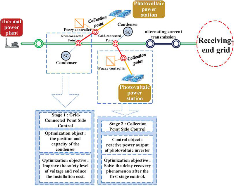
Figure 1 Transient over-voltage control architecture.
Traditionally, synchronous condensers (SCs) have been predominantly and centrally deployed at the converter stations (e.g., rectifier stations) of ultra-high voltage direct current (UHVDC) transmission systems to provide centralized dynamic reactive power support and mitigate commutation failures. However, with the integration of large-scale renewable energy clusters such as photovoltaics (PV), sending-end power grids are increasingly exhibiting “weak grid” characteristics, notably low inertia and a low short-circuit ratio (SCR). In this context, decentralizing the application of SCs from traditional DC converter stations to the grid integration points of renewable energy stations has emerged as a critical engineering trend for enhancing system transient voltage stability.
The distributed configuration of SCs at renewable energy integration points not only provides instantaneous reactive power reserves and short-circuit capacity locally – thereby effectively boosting the SCR of the regional grid – but also leverages the inherent inertia of their physical rotors during complex transient faults. This significantly suppresses the transient voltage fluctuations of PV units and prevents large-scale grid disconnection incidents induced by voltage sags or over-voltages [31, 32]. Compared to singular centralized support at converter stations, this paradigm of “localized compensation and distributed deployment” can more precisely improve the dynamic voltage boundary conditions at renewable energy integration points.
3 Transient Voltage Security Standard and Evaluation Index of Sending-End System
3.1 Transient Voltage Security Standard
Given the dynamic nature of voltage deviations from set limits observed in simulations, the recovery boundary for node voltage should be designed with a time-decreasing margin. Building on the work in reference [33], this study enhances the precision of both voltage and timing control. This approach mandates strict regulation of the voltage span at critical time points to ensure seamless transitional phases. The proposed optimization strategy has a twofold role: On one hand, it functions as an objective function for enhancing the transient voltage security level in subsequent reactive power allocation; on the other hand, it integrates the concept of “boundary distance” into the ensuing fuzzy control stage to enable real-time voltage regulation. Thus, the evaluation timeline is segmented into critical intervals, and an incremental voltage recovery boundary is established within the transient temporal evolution. This configuration strictly limits the voltage boundary span at each time node, ensures the continuity and smooth transition of the recovery trajectory, and establishes the foundation for precise control.
This study establishes a 10-second timeframe for controlling the reactive power voltage throughout the entire post-fault process, encompassing both the fault and recovery periods. The voltage recovery standards are delineated by thresholds through . Specifically, to define the minimum voltage thresholds for successive recovery stages, while to represent the upper voltage limits. In accordance with the Chinese low-voltage ride-through (LVRT) standard for auxiliary inverters in photovoltaic and thermal power units, the voltage tolerance at fault inception is set as the baseline. Consequently, is established at 0.2 p.u. The subsequent lower limits are configured as follows: p.u., p.u., p.u., p.u., and p.u. To account for the brief overvoltage condition expected immediately after fault clearance, the upper limit is set to 1.1 p.u. The corresponding high-voltage thresholds are fixed at p.u., p.u., and p.u. A comparative analysis of the voltage recovery intervals defined in reference [33] and those proposed in this work is presented in Figure 2.
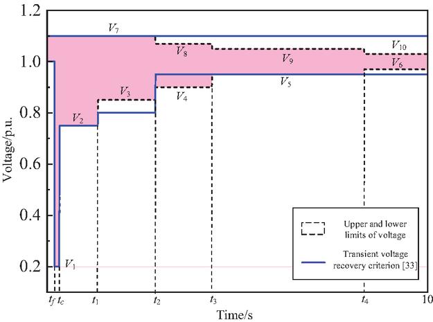
Figure 2 Transient voltage ‘step by step’ voltage recovery boundary.
As shown in Figure 2, key time parameters are defined as follows: tf denotes the instant of fault occurrence, tc represents the moment the fault is cleared, with . Subsequent time points are sequentially determined: ; ; ; . The figure clearly indicates the threshold values corresponding to each time interval. The “step-by-step” voltage recovery boundary line, which describes the allowed transition progression during each critical stage of transient voltage recovery following a node disturbance, characterizes the permissible evolution path. Functionally, this boundary acts as a hard constraint for transient voltage security and offers an intuitive visual representation of voltage constraint values derived from sampled time segments.
3.2 Transient Voltage Security Assessment Index
Aiming at the transient voltage recovery process after node fault disturbance, this article proposes a ‘step by step’ voltage recovery boundary constraint mechanism. Designed to capture the transient behavior of photovoltaic grid-connected systems, this mechanism primarily characterizes the permissible dynamic progression of voltage deviations during critical recovery intervals, thereby establishing a rigorous benchmark for constraining transient voltage stability. Under this theoretical framework, based on the transient voltage security standard established in reference [34], a trajectory offset quantization evaluation model considering the cumulative effect in time domain is constructed. The model establishes a multi-dimensional transient voltage security assessment index system by analyzing the deviation degree of the timing trajectory of the node voltage in the transient process and its dynamic cumulative characteristics:
| (1) |
As defined in Equation (1), the parameter denotes the commencement time of an individual voltage violation incident, while + corresponds to its conclusion time. The variable signifies the aggregate count of limit violations recorded during the entire evaluation period. The expression for is given below:
| (2) |
In Equation (2), and are the high and low voltage crossing boundaries specified in the ‘step by step’ voltage recovery boundary, respectively.
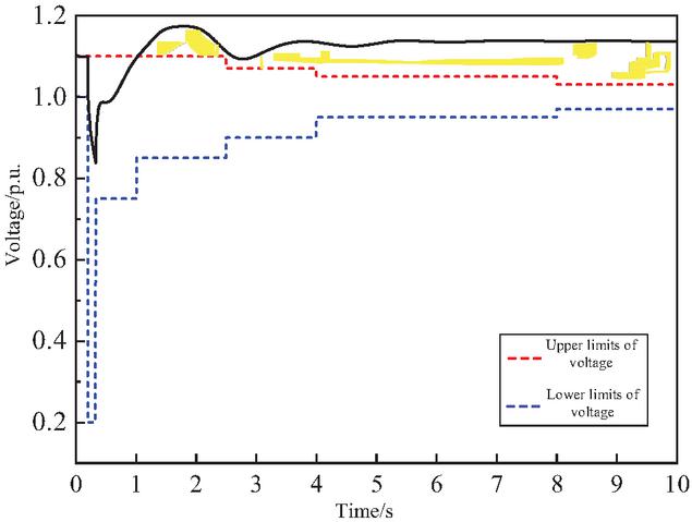
Figure 3 Voltage trajectory and transient voltage security assessment index.
The overall transient voltage security level of the PV station is quantified by the index . This index yields a value of zero when the station’s voltage profile remains within the safe operating standard. Conversely, any excursion beyond the defined voltage limits results in a positive value, which serves as a metric for instability; a higher value corresponds to a more critical instability condition, a relationship depicted in Figure 3.
4 Transient Voltage Control at Grid-Connected Point Side
4.1 Set of Candidate Buses to Be Compensated
Before setting capacity, it is necessary to select candidate buses conducive to reactive power compensation and construct a set of candidate buses to be compensated. To address the need for strategic allocation of dynamic reactive power compensation devices, a sensitivity index based on bus transient voltage security levels is developed. This index informs and guides the distribution process.
(1) Grid operation scenario construction
Based on an analysis of the characteristics of a sending-end grid integrated with large-scale PV generation, typical disturbance scenarios that induce transient voltage instability are identified. Subsequently, a multi-dimensional assessment framework for power system security is developed.
(2) Quantitative analysis of transient voltage security
Leveraging the proposed transient overvoltage security index , this study assesses the transient voltage security level of the photovoltaic station under various fault conditions.
(3) Condenser configuration scheme design
The point-by-point configuration strategy of fixed capacity condenser is adopted to design the installation scheme of each photovoltaic station bus, and the response characteristics of voltage safety index under different configuration positions are calculated.
(4) Condenser configuration effect verification
Establishing a quantitative correlation between synchronous condenser installation sites and system voltage safety improvement, this study evaluates the global optimization effect of the k-group configuration scheme, providing a theoretical foundation for optimal siting.
| (3) |
In Equation (3), parameter denotes the number of considered disturbance fault scenarios.; and represent the transient voltage security index corresponding to the th disturbance fault scenario when the condenser is connected to the th position and the condenser is not connected to the th position, respectively. represents the access capacity of the condenser (assuming that all photovoltaic stations have the same capacity of the condenser).
(5) Calculate the lifting effect and sort it
According to the results calculated in step (4), the larger the value of the voltage safety level improvement effect of the condenser at each installation position is, the greater the contribution of the position to the transient voltage safety level is. To ensure a substantial improvement in the transient voltage security of large-scale renewable energy grids, the optimal condenser installation sites must be accurately identified. This is achieved by first sorting all potential locations according to their effect values and then selecting the top positions as the preferred installation nodes.
4.2 Optimal Configuration of Condenser Capacity
Following the determination of the optimal configuration scheme for the synchronous condenser, the next goal is to identify the optimal capacity allocation for synchronous condenser. This study specifies the objective function as maximizing the system’s transient voltage security level, with the optimization of synchronous condenser costs serving as the primary constraint. To balance safety benefits against economic investment, a multi-objective optimization model is developed, integrating the voltage safety level as a penalty term. Thus, the mathematical representation of this model’s objective function is as follows:
| (4) |
The parameters in Equation (4) are defined as follows: is a binary decision variable (0 or 1) indicating the installation of a reactive power compensation device at node ; denotes the unit capacity price; represents the installed capacity of dynamic reactive power compensation; and is the set of candidate nodes. During optimization, adherence to the following principle is mandatory: if transient voltage security constraints are met, the solution with the lower compensate ion cost is selected; if not met, the solution yielding a higher security level is preferred. Based on this principle, the objective function is constructed as follows:
| (5) |
In the Equation (5), is a penalty function factor, which is a maximum value. As long as the objective function value when is not equal to 0 is greater than the objective function value when is equal to 0.
4.3 Constraint Condition
(1) Power balance constraints
| (6) |
The parameters in Equation (6) are defined as follows: , , , , denote the active power output, reactive power input, active power load, reactive power load, and voltage magnitude at node , respectively. Similarly, , and represent the conductance, susceptance, and phase angle difference of branch -, respective
(2) Variable constraints
Constraints on variables are bifurcated into two categories: constraints on state variables and constraints on control variables. State variables encompass the generator’s active power output (), reactive power output (), steady-state voltage magnitude at nodes (), among others. Control variables, in turn, involve the installed capacity () of reactive power compensation devices.
The state variable constraint
| (7) |
control variables constraint
| (8) |
The parameters in Equation (7) are defined as follows: , , and denote the number of generator nodes, the total number of system nodes, and the count of reactive power compensation candidate nodes, respectively. The superscripts max and min indicate the upper and lower limits of the variables, respectively.
4.4 Mathematical Model and Solving
In summary, a mathematical model for the optimal configuration of dynamic reactive power, which incorporates the enhancement of the transient voltage security level, is formulated herein.
| (9) |
Within Equation (9), denotes the objective function; and are the vectors of control and state variables, respectively; and define equality and inequality constraints composed of state variables; and represents the dimension of the control vector.
Accordingly, Dung Beetle Optimization Algorithm, a widely adopted swarm intelligence technique for tackling optimization challenges, is employed to obtain the solution.
5 Transient Voltage Control at The Collection Point Side
5.1 Feedback Signal Extraction of Fuzzy Controller
When designing a fuzzy controller, the primary task is a reasonable selection mechanism based on input variables and output variables. Therefore, the two-dimensional dynamic characteristics of voltage trajectory are proposed as the core feedback variables, which are defined as: voltage deviation () and voltage trajectory variation coefficient () respectively represent the degree of system voltage deviation from the rated value and are used to quantify the trend of voltage convergence from abnormal state to safe interval. The two constitute the two-dimensional state vector of the voltage trajectory, which not only covers the amplitude deviation characteristics of the transient process, but also reflects the behavior characteristics of the system dynamic recovery. On this basis, the output variable selects the reactive power () closely related to the voltage, and drives the voltage trajectory to converge to the security domain by adjusting the reactive power compensation output by the inverter in real time. The design ensures fast and robust voltage control by mapping the dynamic relationship between voltage trajectory and reactive power compensation through fuzzy logic adaptive mapping.
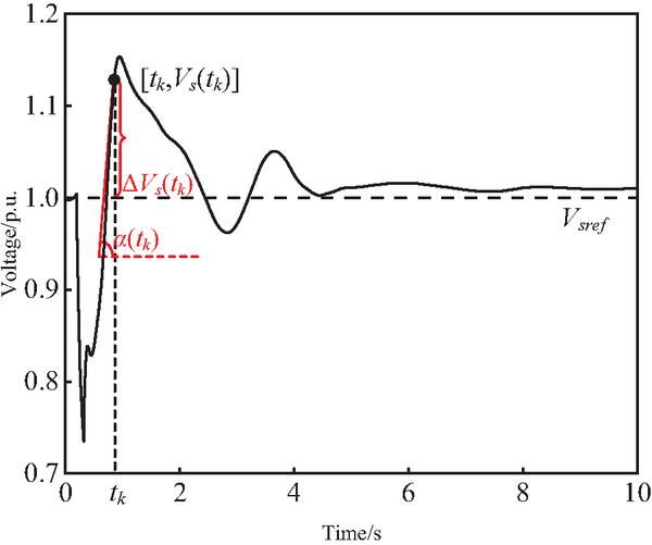
Figure 4 Input signal extraction diagram of fuzzy controller.
As illustrated in Figure 4, the fuzzy controller utilizes two input signals. The primary input is the voltage deviation, denoted by , where is the standard voltage value of 1.0 p.u. The secondary input is the voltage trajectory change coefficient, expressed as , which is the sine of the phase angle reflecting the recovery direction.
5.2 Fuzzy Controller Design
Figure 5. describes the structure of the fuzzy controller, which includes two signal input terminals and a variable output terminal, and two main modules: trigger and fuzzy logic system.
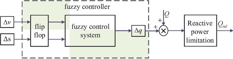
Figure 5 Logic diagram of fuzzy controller.
The trigger mechanism of the fuzzy controller employs a double-threshold voltage violation criterion. To integrate with the “stepwise” voltage recovery boundary and conserve control resources, a safety warning distance (i.e., a safety margin) between the voltage recovery boundary and the voltage trajectory is defined as 0.03 p.u. (). Triggering occurs when the voltage trajectory deviates from the final upper/lower limits of the step boundary (voltage amplitude 0.97 p.u. or 1.03 p.u.) and remains within this safety margin, prompting the fuzzy control algorithm to enter a dynamic adjustment state. Conversely, if the voltage operates within the safe range (0.97–1.03 p.u.) or the trajectory exceeds the safety margin, the controller remains inactive to minimize system disruption. The specific control process is illustrated in Figure 9.
Guided by the safety warning distance, the trigger fuzzy control system prioritizes the millisecond response capability of renewable energy. To address unknown faults, it establishes a reserved control threshold while fully utilizing the reactive power regulation function of the photovoltaic inverter. The system also prevents the controller from activating fuzzy control during the voltage recovery phase, thereby avoiding frequent equipment actuation. The designed fuzzy controller can independently complete the operation state evaluation based on local measurement information. Control the action process of decision generation and adjustment instruction execution. Maximize reactive power within the capacity constraints of renewable energy stations Supporting ability.
The controller achieves closed-loop feedback of the reactive power compensation output by applying Equation (10):
| (10) |
Here, represents the reactive power regulation output from the fuzzy control, and denotes the actual reactive power demand of the system. To safeguard the inverter hardware, an overcurrent constraint, as specified in Equation (11), must be satisfied.
| (11) |
Per the grid-integration standard for photovoltaic systems, the inverter is required to dynamically regulate its power factor under rated active power output. This enables reactive power support within a range of 0.95 leading to 0.95 lagging, thereby ensuring the stability of the grid voltage.
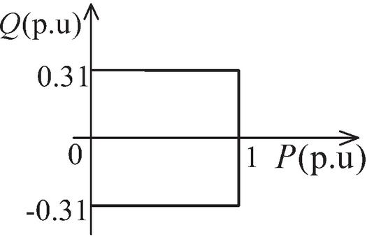
Figure 6 Inverter reactive power output range.
The core architecture of fuzzy logic includes three key modules:
(1) Fuzzification: The voltage control processing problem belongs to the continuous change control problem, so the Gaussian membership function with smooth transition and no obvious inflection point is used for processing, as shown in the Equation (12). The Gaussian membership function is used to normalize the input variables (, , ), and the domains are [, ], [, ], [, ]. The membership function is divided into seven semantic items, as shown in Figure 7.
| (12) |
is the center point of the function, which determines the position of the membership function.
is the width parameter, which determines the width of the membership function.
(2) Rule reasoning: Formulated using expert experience, the fuzzy control rule base captures the nonlinear mapping relationship between input and output variables.
(3) Defuzzification: The barycenter method converts fuzzy inference outcomes into accurate control values, thereby ensuring the enforceability of output instructions.
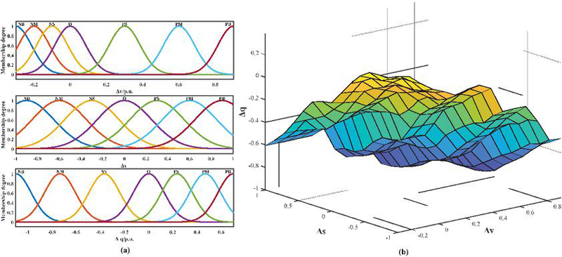
Figure 7 (a) Input and output membership function and (b) input-output mapping surface.
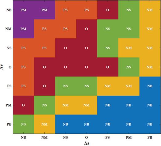
Figure 8 Fuzzy rule setting.
The fuzzy inference rules are shown in Figure 8. All fuzzy rules are generated by the following principles:
(1) In the event of a node voltage sag with a negative voltage trajectory index, indicating persistent degradation of the voltage level, the system must dispatch devices to output peak reactive power compensation for immediate stabilization.
(2) If a voltage sag is accompanied by a positive trajectory index, the voltage is considered to be in a state of spontaneous recovery. Consequently, only marginal reactive support or no intervention is necessary to ensure operational security.
(3) When a voltage swell occurs alongside a positive trajectory index, signaling an intensifying over-voltage risk, the system should command maximum reactive power absorption to rigorously counteract the voltage rise.
(4) Should a voltage rise occur with a negative trajectory index, the over-voltage state is deemed to be self-mitigating, necessitating only minimal reactive absorption or maintenance of the current operational state.
Thus, the two-stage control process designed to enhance the transient voltage security level of large-scale new energy sending-end power grids is illustrated in Figure 9.
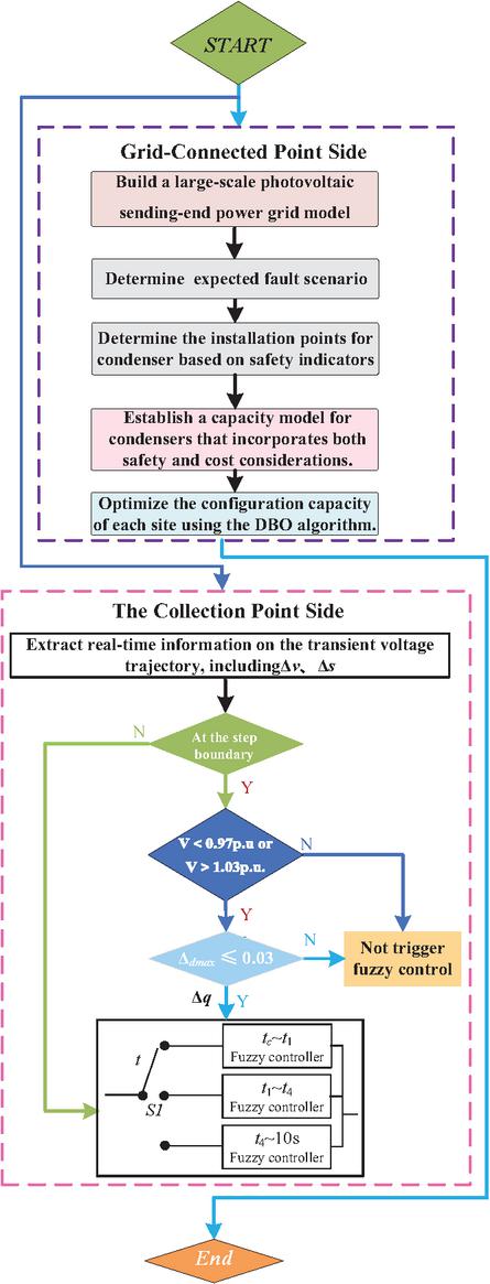
Figure 9 Control optimization control process.
6 Case Study
6.1 Example Description
As shown in Figure 10, part of the synchronous generator in the Nordic system is replaced by a photovoltaic system, the Nordic photovoltaic access to the sending-end system supplies power to the receiving-end system. The Nordic system has four regions (Equiv, North, South and Central), including a total of 22 generators, 77 buses, and 22 loads. The central region is a high-load power receiving area containing 11 loads, which is transported from the northern and southern regions to the central region.
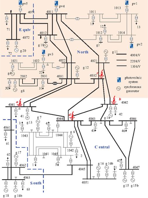
Figure 10 Modified Nordic node diagram.
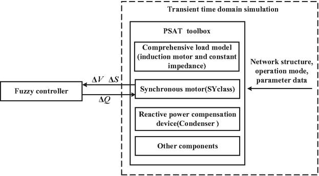
Figure 11 Schematic diagram of fuzzy control interactive interface based on PSAT.
Focusing on the transient voltage stability problem, the model integrates the dynamic characteristics of synchronous generators, including their excitation systems and speed control mechanisms. Utilizing the MATLAB/PSAT co-simulation platform’s bidirectional communication architecture, real-time data interaction and instruction transmission are realized in time-domain simulations (schematic in Figure 11). With the photovoltaic power station cluster modeled as a PQ node (SPQclass mode), MATLAB and its PSAT toolbox enable modeling, simulation, and numerical solution. Notably, for millisecond transient processes, step size selection balances accuracy and efficiency: if too large, simulation precision drops (missing true dynamics) and numerical instability arises (error accumulation); if too small, computational overload impedes feature extraction. After iterative verification, a 0.01 s step size and 10 s termination time are adopted, ensuring voltage convergence to the transient steady state.
According to the operation state of the system, the output of PV1–PV5 is 300 MW, 550 MW, 200 MW, 668 MW and 300 MW respectively. The ratio of photovoltaic output to total power output in the sending-end power grid is 56 %. According to the requirements of grid-connected specifications, each photovoltaic inverter needs to have the dynamic adjustment ability of power factor from 0.95 to 0.95 under rated active output.
In order to investigate the voltage safety characteristics of the central region, four key tie lines between the north-south region and the central region are specially selected to apply fault disturbance (as shown in the marked points of Figure 10), and the fault types are all three-phase ground short circuits. This setting can effectively simulate the phenomenon of insufficient transient voltage support and recovery delay caused by grid fault after large-capacity photovoltaic access, and has typical voltage stability research value. Based on the two factors of fault location and renewable energy penetration rate, two scenarios (encompassing 8 examples as shown in Table 1) were established to assess the effectiveness of the proposed control strategy. The method’s efficacy and applicability are verified via a more detailed simplified representation of the actual power system model.
Table 1 Scenario introduction
| Renewable Energy | ||||
| Scenario | Example | Penetration Rate | Fault Clearing Time | Fault Position |
| Scenario 1 | 1 | 56% | 0.32s | 4032 |
| 2 | 56% | 0.32s | 4044 | |
| 3 | 56% | 0.32s | 4041 | |
| 4 | 56% | 0.32s | 4042 | |
| Scenario 2 | 5 | 50% | 0.32s | 4032 |
| 6 | 50% | 0.32s | 4044 | |
| 7 | 50% | 0.32s | 4041 | |
| 8 | 50% | 0.32s | 4042 |
6.2 Transient Voltage Characteristics without Condenser Configuration
Through comparative analysis for the simulation needs of multiple examples, this paper demonstrates the effectiveness of the whole-process voltage control. Figure 12 illustrates the transient voltage response characteristics of all nodes across each example in the absence of control measures.
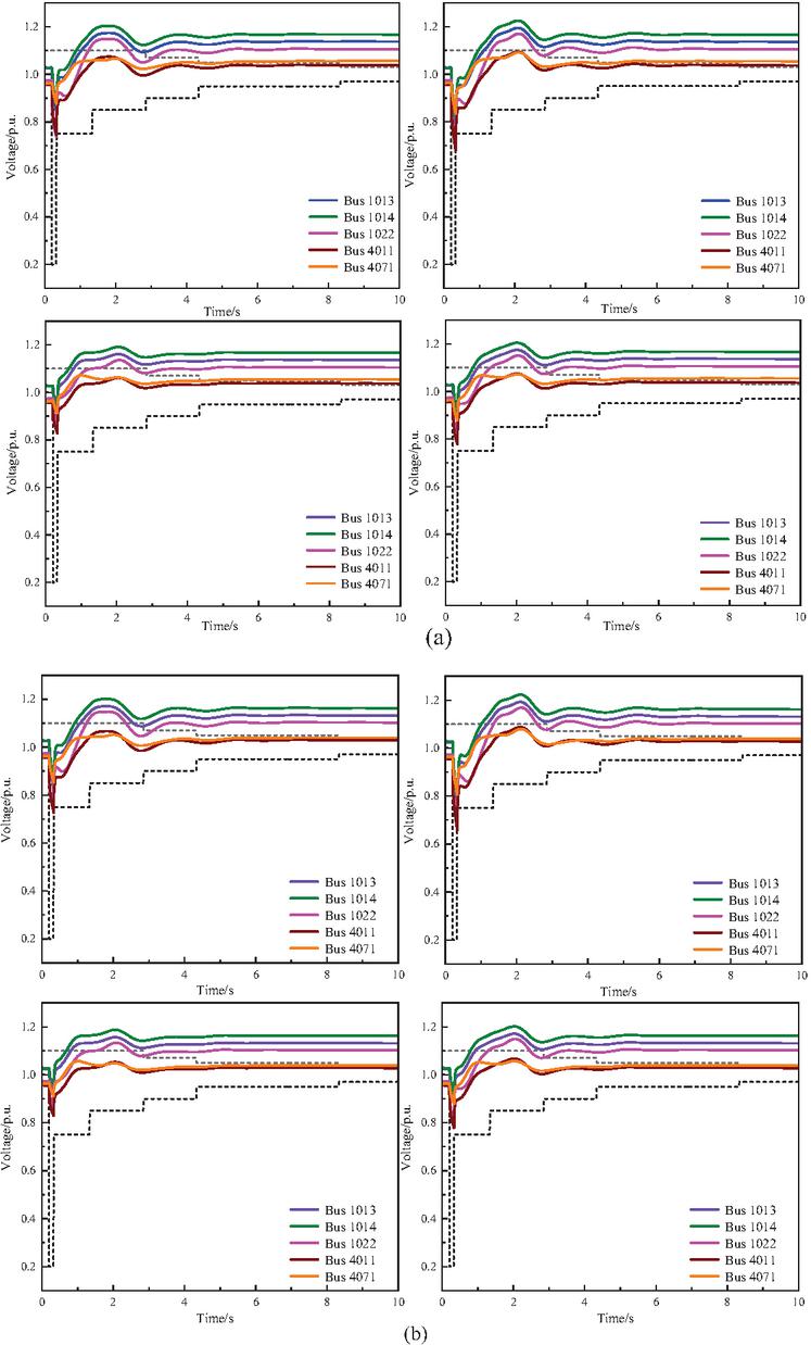
Figure 12 Voltage trajectory diagram of unconfigured condenser.
Simulation results indicate that, under diverse fault types, the transient voltage at each bus prior to control exhibits pronounced overvoltage traits during the period from fault clearance to simulation end. In the event of a short-circuit fault, the photovoltaic inverter significantly increases reactive power injection due to the mandatory output of reactive current in the fault’s initial stage. After fault clearance, while the grid voltage rises rapidly, the new energy unit maintains a high level of reactive power support – attributed to a delay in the control system’s dynamic response – leading to a temporary voltage overshoot that forms transient overvoltage.
6.3 Voltage Control Effectiveness at the Grid Connection Point
Based on the method proposed in Section 4.2, the installation location of the synchronous condenser is selected. By installing 50 Mvar synchronous condensers one by one at the bus of the photovoltaic power station, the overall voltage safety improvement effect of the photovoltaic field of the sending end power grid in three scenarios is obtained and sorted for each fault traversal. The relevant parameters are applied to the synchronous condenser that has been put into operation, and the results are shown in Table 2.
Table 2 for different installation positions of the condenser
| Installation location of condenser | |
| 1013 | 0.2591 |
| 1014 | 0.2393 |
| 1022 | 0.2024 |
| 4071 | 0.1801 |
| 4011 | 0.1393 |
In this paper, for the site selection of condensers, the three buses with the highest transient voltage sensitivity index – 1013, 1014, and 1012 – were selected as installation nodes. Based on the determined nodes, the Dung Beetle Optimizer (DBO) algorithm was applied to solve the optimal configuration model for condensers constructed in Section 4.2. The unit cost of reactive power compensation, , was set at 500,000 yuan/Mvar. The main parameters of the DBO algorithm are configured as follows: population size is 30, maximum number of iterations is 100; the proportions of ball-rolling, foraging, breeding, and stealing dung beetles are 0.2, 0.2, 0.5, and 0.1, respectively. Additionally, the ball-rolling probability threshold is 0.9, ball-rolling disturbance coefficient is 0.1, foraging disturbance coefficient is 0.05, stealing disturbance coefficient is 0.1, and breeding range coefficient is 0.5.
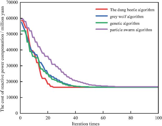
Figure 13 Algorithm iteration comparison diagram.
Compared with other optimization algorithms, the dung beetle optimization algorithm has fewer iterations and better convergence. The configuration results are bus 1013 synchronous condenser 135 Mvar, bus 1014 synchronous condenser 120 Mvar, bus 1012 synchronous condenser 75 Mvar.
Based on the aforementioned capacity configuration, a subsequent simulation analysis was performed to investigate the voltage behavior of the sending-end grid under various fault scenarios. As illustrated in Figure 14. the voltage trajectories of the PV plant’s grid-connected bus are presented.
From Figure 14, it can be seen that after optimizing the configuration of the condenser, when faults occur in different scenarios under different operating modes, the peak value of the bus voltage of the photovoltaic unit can meet 1.1 pu or less, and the bus voltage can operate within the allowable voltage safety range. Compared with the peak bus voltage of the condenser, the bus voltage has a significant inhibitory effect and can alleviate the voltage drop during the fault to a certain extent. However, the range of voltage and rated voltage in the recovery stage after overvoltage is too large, which reflects the importance of photovoltaic inverter in hierarchical control.
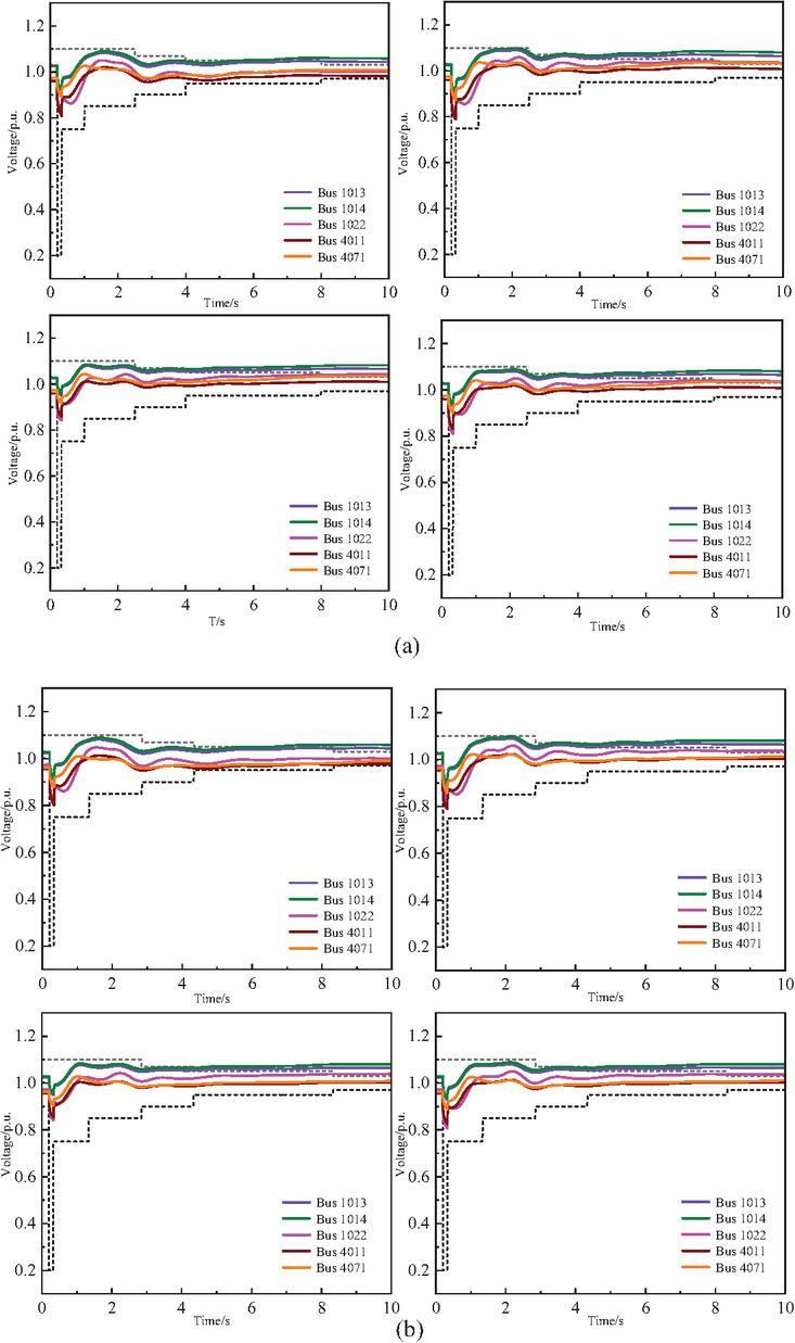
Figure 14 Voltage trajectory diagram of configured condenser.
6.4 Comparison of Support Effectiveness Between Condensers and PV Inverters
To demonstrate the superiority of the short-term reactive power support capability offered by the synchronous condenser relative to photovoltaic inverter control, a comparison was conducted on transient voltage control under two strategies: synchronous condenser control and photovoltaic system control. Specifically, this comparison was implemented in Example 1 and Example 2.
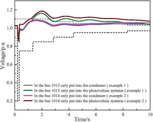
Figure 15 Support capacity comparison diagram.
From Figure 15, it can be observed that compared with the voltage trajectory diagram without control in Figure 15, whether it is only controlled by the photovoltaic system or only by the condenser, it can achieve a certain effect on the transient voltage peak control in a short period of time. Bus 1013 and 1014 can control the overvoltage peak at 1.16 pu and 1.18 pu in 2.05 s and 2.10 s respectively under the control of the photovoltaic system, while under the control of the condenser, the two nodes can control the overvoltage peak at 1.08 pu in 1.58 s and 1.61 s respectively. Therefore, the short-term reactive power support ability of the peak-up camera is superior in time.
6.5 Voltage Control Effectiveness at the Collecton Point Side
Through the support of the synchronous condenser, the sending end system can control the overvoltage peak value below 1.1 pu, and the transient voltage security level is obviously improved. However, the voltage in the recovery stage is still maintained in the suspended high voltage state, and the fuzzy adaptive control is introduced in the second stage. The image after the whole process is controlled is shown in Figure 16.
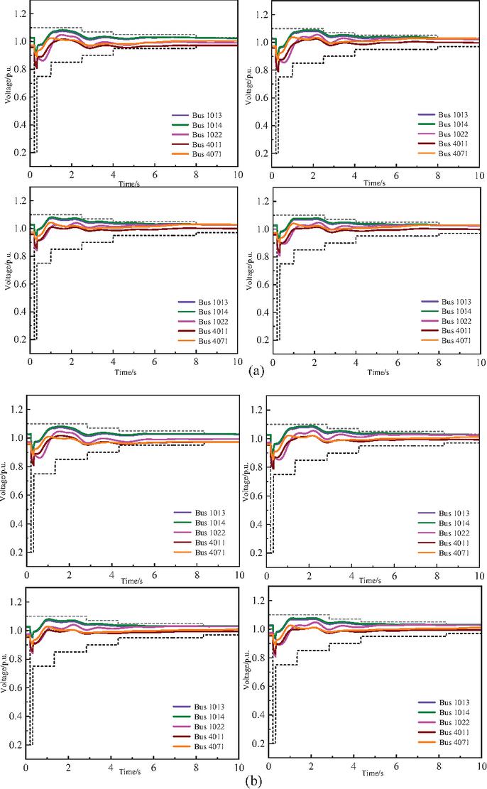
Figure 16 Voltage trajectory diagram after fuzzy control.
It can be clearly seen from the simulation results that the introduction of fuzzy control strategy plays a vital role. Fuzzy control can dynamically adjust control parameters according to real-time voltage deviation and change rate, so as to achieve precise coordinated control of photovoltaic inverters.
In the recovery phase, the voltage is strictly operated within the preset safety boundary at each time node, as shown in Table 3.
Table 3 Comparison of ITOV before and after two-stage control
| Example | Without Condenser | With Condenser | After Fuzzy Control |
| 1 | 0.8965 | 0.2367 | 0 |
| 2 | 0.7896 | 0.2458 | 0 |
| 3 | 0.7543 | 0.1452 | 0 |
| 4 | 0.8762 | 0.1423 | 0 |
| 5 | 0.8375 | 0.2453 | 0 |
| 6 | 0.8001 | 0.2291 | 0 |
| 7 | 0.7813 | 0.1562 | 0 |
| 8 | 0.8862 | 0.1625 | 0 |
While only the synchronous condenser control can achieve voltage support during faults and in the short period following fault clearance, the remains greater than 0 – signifying a persistent phenomenon of offsetting the upper and lower boundaries. However, with the introduction of fuzzy control, it is visually evident from numerical results that under the proposed adaptive reactive power fuzzy control strategy, the voltage evolution trajectory adheres to the standard requirements.
6.6 Comparison between Fuzzy Control and Droop Control
To demonstrate the superiority of the proposed strategy relative to conventional strategies, a comparison is conducted between the proposed control strategy and droop control in Example 2, with the results presented in Figure 17.
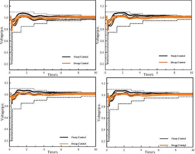
Figure 17 Two control comparison diagrams.
As illustrated in Figure 17, relative to the traditional control strategy, both control strategies are capable of regulating voltage within a controllable interval during the effective time. However, the triggering mechanism of fuzzy control in this paper enables dynamic reduction in action frequency and total reactive power output, while maintaining voltage regulation within the specified interval during the given time. In contrast, droop control can only persist in acting according to preset conditions. Regulated via fuzzy control and droop control (summarized in Table 4) across Scenario 1 cases, photovoltaic systems use the sum of absolute reactive power adjustments to quantify control effects.
Table 4 Absolute value of reactive power
| Example | Droop Control | Fuzzy Control |
| 1 | 11.345 | 5.636 |
| 2 | 9.643 | 6.741 |
| 3 | 10.846 | 4.446 |
| 4 | 10.255 | 5.162 |
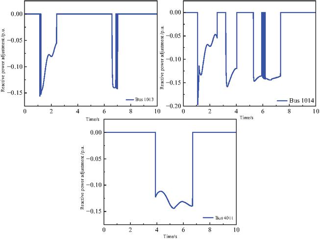
Figure 18 Photovoltaic reactive power adjustment at Example 5.
Compared to droop control, fuzzy control achieves equivalent voltage regulation with reduced reactive power output. To examine the dynamic response mechanism of photovoltaic stations in reactive compensation, the reactive power output frequency is analyzed. One representative cases from Scenario 2 show reactive power dynamics in Figure 18. Critically, the security early warning-triggered fuzzy controller with boundary constraints avoids frequent actuation while ensuring compensation.
Through the adjustment of reactive power and the change of voltage trajectory of photovoltaic grid-connected point under the fault scenarios, the synchronous condenser is strongly supported in the overvoltage stage, and the photovoltaic system is finely controlled in the recovery stage, so that the optimized adaptive reactive power fuzzy control node meets the standard requirements.
7 Conclusion
In this paper, a transient overvoltage hierarchical control strategy of ‘grid-connected point-photovoltaic power station collection point’ is proposed.
(1) This paper innovatively constructs a voltage recovery boundary based on transient voltage security constraints. This boundary can not only be used as the core safety criterion at the control level of the point of common coupling. It also calculates the deviation between the running state and the boundary in real time at the control layer of the collection point to realize the control.
(2) By optimizing the position and capacity of synchronous condensers, grid-connected point side control enhances their reactive power support capacity. Through rapid reactive power injection during faults, it mitigates sudden transient voltage variations and overvoltage risks.
(3) The core of the proposed strategy is a transient voltage control framework based on dynamic distance quantization of voltage recovery boundaries. Its strength resides in synergizing the photovoltaic power station’s reactive regulation with fuzzy adaptive control, which significantly boosts the dynamic recovery of transient voltage.
The control method effectively manages voltage across the entire fault lifecycle of the sending-end system. Its applicability to diverse disturbance scenarios in real-world systems underscores its strong versatility.
While this paper has conducted relevant research and achieved certain results in the transient voltage control of photovoltaic sending-end systems, the continuous evolution of modern power systems presents numerous issues that warrant further exploration. Future research can be carried out from the following aspects:
(1) Expansion to complex fault scenarios: This paper primarily conducts analysis based on conventional symmetrical short-circuit faults. Future work could further investigate the transient voltage evolution mechanisms and control strategies of PV systems under the context of complex cascading faults.
(2) Integration of multi-energy complementary systems: The current research mainly focuses on PV generation systems. Subsequent studies could introduce other forms of renewable energy, such as wind power, to explore the more complex reactive power allocation and coordination mechanisms under wind-solar-thermal multi-source coupling and higher renewable energy penetration.
(3) Introduction of intelligent control algorithms: Building upon the existing fuzzy control framework, future research could attempt to incorporate advanced data-driven algorithms, such as deep reinforcement learning. This would reduce the reliance on empirical parameter tuning and further enhance the adaptive optimization capabilities of the control strategy under unforeseen operating conditions.
Acknowledgements
This work is funded by the Jilin Provincial Natural Science Foundation for Distinguished Young Scholars (Grant No. 20230101354JC).
References
[1] Holttinen H, Groom A, Kennedy E, et al. Variable renewable energy integration: Status around the world[J]. IEEE Power and Energy Magazine, 2021, 19(6): 86–96.
[2] Kumar M, Acharya D S, Mishra P, et al. Mitigating low inertia challenges in renewable energy-based microgrids: A survey[C]. 2025 IEEE 1st International Conference on Smart and Sustainable Developments in Electrical Engineering (SSDEE), 2025: 1–7.
[3] Hu Z, Wang D, Li M, et al. Research on the high proportion consumption mechanism of renewable energy to promote the green and low-carbon transformation of energy[C]. 2023 2nd International Conference on Power Systems and Electrical Technology (PSET), 2023: 196–200.
[4] Liu D, Zhang X, Tse C K, et al. Effects of high level of penetration of renewable energy sources on cascading failure of modern power systems[J]. IEEE Journal on Emerging and Selected Topics in Circuits and Systems, 2022, 12(1): 98–106.
[5] Chand S S, Hredzak B, Farhangi M, et al. Adaptive control of grid-following inverter-based resources under low network short circuit ratio[J]. IEEE Transactions on Industry Applications, 2025, 61(2): 1828–1838.
[6] Li M. Optimizing resilience and sustainability: A tri-level energy management framework for multi-energy microgrids with power-to-hydrogen technology[J]. Strategic Planning for Energy and the Environment, 2025, 44(4): 957–992.
[7] He S, Zhang J, Rong W, et al. Application of a source-grid-load-storage intelligent fusion terminal in power grid dispatch optimization[J]. Strategic Planning for Energy and the Environment, 2026, 45(1): 47–76.
[8] Luo Q, He X, Liao X, et al. Cavitation feature extraction method of hydraulic turbine based on NS-TEMD and cross fuzzy entropy[J]. Strategic Planning for Energy and the Environment, 2025, 44(3): 565–580.
[9] Sun D, Wu L, Liu H, et al. Effect of the low voltage ride through characteristics on PMSG terminal transient voltage in weakly-synchronized gird[J]. Proceedings of the CSEE, 2021, 41(14): 4777–4786.
[10] Liu Z Y, Zhang Q P, Wang Y T, et al. Research on reactive compensation strategies for improving stability level of sending-end of 750 kV grid in Northwest China[J]. Proceedings of the CSEE, 2015, 35(5): 1015–1022.
[11] Xu G R, Wang L G, Li Z J, et al. Improvement of reactive power consumption ability for dual-excited synchronous condenser[J]. IEEE Transactions on Industry Applications, 2024, 60(4): 6056–6065.
[12] Zhou F Q, Wang X T, Zhao Z Y, et al. Reactive power absorption capability of dual-excited condenser with symmetric excitation scheme[C]. 2024 The 9th International Conference on Power and Renewable Energy (ICPRE), 2024:530–534.
[13] Wang K, Li Z H, Yang C R, et al. Siting method of synchronous condenser for small-signal stability improvement of large-scale renewable energy base[J]. Automation of Electric Power Systems, 2022, 46(4): 66–74.
[14] Hadavi S, Mansour Z, Bahrani B, et al. Optimal allocation and sizing of synchronous condensers in weak grids with increased penetration of wind and solar farms[J]. IEEE Journal on Emerging and Selected Topics in Circuits and Systems, 2021, 11(1): 199–209.
[15] Hadavi S, Saunderson J, Mehrizi-Sani A, et al. A planning method for synchronous condensers in weak grids using semi-definite optimization[J]. IEEE Transactions on Power Systems, 2023, 38(2): 1632–1641.
[16] Marrazi E, Yang G, Weinreich-Jensen P, et al. Allocation of synchronous condensers for restoration of system short-circuit power[J]. Journal of Modern Power Systems and Clean Energy, 2018, 6(1): 17–26.
[17] Han Z, Jia Q, Dong W, et al. Optimal allocation of distributed synchronous condenser for SSO mitigation[C]. The 12th International Conference on Renewable Power Generation, 2023: 1–6.
[18] Suo Z, Li H, Zhang F, et al. Optimal configuration of a distributed synchronous condenser for an HVDC sending-end system with a high proportion of renewable energy[J]. Power System Protection and Control, 2022, 50(23): 133–141.
[19] Zhou Y, Sun H, Xu S, et al. Synchronous condenser optimized configuration scheme for power grid voltage strength improvement[J]. Power System Technology, 2022, 46(10): 3848–3856.
[20] Yang H, Li N, Sun Z L, et al. Real-time adaptive UVLS by optimized fuzzy controllers for short-term voltage stability control[J]. IEEE Transactions on Power Systems, 2022, 37(2): 1449–1460.
[21] Bi C B, Liu D, Zhu L P, et al. Short-term voltage stability emergency control strategy pre-formulation for massive operating scenarios via adversarial reinforcement learning[J]. Applied Energy, 2025, 389: 125751.
[22] Jiang C X, Liu C X, Yuan Y J, et al. Emergency voltage control strategy for power system transient stability enhancement based on edge graph convolutional network reinforcement learning[J]. Sustainable Energy, Grids and Networks, 2024, 40: 101527.
[23] Huang R, Chen Y, Yin T, et al. Accelerated derivative-free deep reinforcement learning for large-scale grid emergency voltage control[J]. IEEE Transactions on Power Systems, 2022, 37(1): 14–25.
[24] Zhao Y C, Zhang G Z, Hu W H, et al. Meta-learning based voltage control strategy for emergency faults of active distribution networks[J]. Applied Energy, 2023, 349: 121399.
[25] Chen Q, Zhao Q, Zhang W, et al. Decentralized robust emergency voltage control of power system with large-scale wind power integrated via VSC-MTDC[J]. IEEE Transactions on Industry Applications, 2024, 60(5): 7522–7536.
[26] Yang N, Zhang G L, Guo D B, et al. Emergency reactive power fuzzy adaptive control strategy for wind-solar-fire coupled system oriented to refined voltage recovery requirements[J]. Electric Power Systems Research, 2025, 241: 111369.
[27] Zhou Z, Xia C, Peng B, et al. Application research on transient stability control strategy tables in power systems[J]. Power System Technology, 2000, 24(1): 13–15.
[28] Standardization Administration of China (SAC). Technical Regulations for Wind Farms Connected to Power Systems: GB/T 19963-2021 [S]. Beijing: China Standards Press, 2021.
[29] Han M X, Zheng Z K, Zheng J H, et al. Development trend of grid transient voltage support technology for renewable energy stations[J]. Power System Technology, 2023, 47(4): 1309–1327.
[30] Lou X S, Ma G, Guo C X, et al. Coordinated risk control system and architecture design for whole-process power grid operation[J]. Automation of Electric Power Systems, 2020, 44(5): 161–170.
[31] Yang H, Liu H, Ding Z H, et al. Two-stage optimal configuration of synchronous condensers in sending-end grid with high proportion of wind power considering short-circuit ratio improvement and transient overvoltage suppression[J]. Power System Technology, 2024, 48(02): 540–552.
[32] Jin Y D, Yu Z, Li M J, et al. Comparison of application between new generation synchronous condenser and power electronic reactive power compensation device in UHV AC/DC power grid[J]. Power System Technology, 2018, 42(7): 2095–2102.
[33] Zhu L P, Luo Y H. Deep feedback learning based predictive control for power system undervoltage load shedding[J]. IEEE Transactions on Power Systems, 2021, 36(4): 3349–3361.
[34] Gu Y, Guo D, Gu Y, et al. Vulnerability ranking and identification of AC fault nodes in coupled systems based on IFAHP-IMABAC method[J]. Electric Power Systems Research, 2024, 228: 110053.
Biographies

Yu Wu, male, is currently a master’s degree candidate in Electrical Engineering at Northeast Electric Power University. His primary research focus lies in transient voltage control.

Chuang Liu, male, is currently a doctoral supervisor and professor in Electrical Engineering at Northeast Electric Power University. His primary research focus lies in flexible operation and control of distribution grids.

Dongbo Guo, male, is currently an in-service postdoctoral researcher at Tsinghua University. His research primarily focuses on direct AC/AC power conversion theory and its applications.

Ruifeng Li, male, is currently a doctoral candidate at Northeast Electric Power University. His research primarily focuses on direct AC/AC power conversion technology and its application in multimodal control of distribution grids.

Wuyi Zhou, female, is currently a master’s degree candidate in Electrical Engineering at Northeast Electric Power University. Her primary research focus lies in voltage control of distribution grids.
Strategic Planning for Energy and the Environment, Vol. 45_3, 647–682
doi: 10.13052/spee1048-5236.4532
© 2026 River Publishers