Realization of an Optimum Load for Wireless Power Transfer System
Chaoling Wang and Qi Wu
1School of Electronics and Information Engineering
Beihang University, Beijing, 100191, China
wangchaoling@buaa.edu.cn
2Department of Fundamental Research
Zhongguancun Laboratory, Beijing, China
qwu@buaa.edu.cn
Submitted On: February 22, 2023; Accepted On: April 27, 2023
ABSTRACT
Wireless power transfer (WPT) system has been an integral part of personal living since its regained interest, especially the magnetic resonance (MR) scheme. MR-WPT scheme suffers, however, change of the coil separation distance and various alignment errors. This paper reports a realization of optimum load for MR-WPT system, which can change the loading impedance accordingly for different coupling coefficients between the Tx and Rx coils. A simple varactor circuit is adopted to realize the optimum load curve. Usefulness of this is demonstrated through both the steady and transient analysis. The proposed realization relies on an open-circuit scheme, and hence it is suitable for scenarios with low-cost and small-size requirements.
Index Terms: Coupling coefficient, load impedance, magnetic resonance, wireless power transfer.
I. INTRODUCTION
Wireless power transfer (WPT) technology has regained interest since the demonstration of magnetic resonance (MR) WPT scheme [1–4]. The basic elements of the MR-WPT system consist of a power source, a Tx coil, a Rx coil, and a termination load [5–7] The Tx and Rx coils of the MR-WPT system must be resonant at the same frequency to achieve the optimum power transfer efficiency [8]. In addition, the load impedance must comply with the coupling coefficient of the Tx and Rx coils in order to obtain the maximum transfer efficiency or the highest output voltage after rectification [9–11]. The requirement of an optimum load impedance poses a strict limitation on the scenarios for practical use. For instance, if a fixed load impedance is adopted in the MR-WPT system, the users must make a very precise alignment of the Tx and Rx coils with appropriate separation distance. It is difficult to achieve such an accurate alignment in a WPT system, charging a mobile phone or an electric vehicle, for example.
To overcome the limitations of accurate alignment of Tx and Rx coils in the MR-WPT system, a variable load impedance approach can be adopted. A strict derivation of an optimum load impedance has been discussed in a few works [6], [12]. In addition, a massive number of measurements were performed and a detailed diagram of the transfer efficiency and separation distance was obtained [13]. Those works build a solid background of the optimum load in MR-WPT systems.
Realization of optimum load impedance has been an active research topic in the past decade. In general, two different approaches have been extensively discussed: Closed-loop and open-loop scenarios. The closed-loop scenarios usually enjoy better flexibility and also slightly higher efficiency. For instance, two switch-controlled capacitors were added to the Tx and Rx coils for optimizing the transmission efficiency [14]. The operating frequency of MR-WPT can be also alternated in a closed-loop fashion through variable compensation capacitors with a constant load [15]. Several other closed-loop scenarios were also reported using reconfigurable structures to achieve high energy efficiency over different load impedances [16–19]. One drawback of the closed-loop WPT system is high complexity in the whole system. Therefore, the open-loop WPT system is favored for low-cost applications. In addition, for the case with multiple Rx coils, the open-loop architecture is more flexible to use [20].
In this paper, a new realization of an optimum load for WPT systems is reported, which can change the loading impedance accordingly for different coupling coefficients between the Tx and Rx coils. A simple varactor circuit is adopted to realize the optimum load curve. Usefulness of this realization is demonstrated through both the steady and transient analysis. The proposed realization relies on an open-circuit scheme, and hence it is suitable for the scenarios with low-cost and small-size requirements.
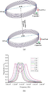
Figure 1: (a) Structural diagram of the WPT system, and (b) power transfer efficiency versus the separation distance between the Tx and Rx coils.
II. STATEMENT OF THE PROBLEM
A two-coil WPT system shown in Fig. 1 is discussed in this paper. The Tx and Rx coils are identical, and their structural parameters are the same as the case studied in [12]. The coils have a diameter of 8 cm and 10 turns. For practical use, diameter of the Tx and Rx coils should be determined by the allowed space for accommodating these coils. It is also noted that the optimum separation distance between the Tx and Rx coils is usually in the same order as the diameter of the coils [21]. Therefore, there is a fundamental trade-off between the size and coverage area for the coils. Moreover, turns of the coils would determine their resonant frequency. If the resonant frequency is lower than the desired one, an additional capacitor may be used to tune the resonance, as illustrated in Fig. 1 (a). In the presented configuration, the first anti-resonance frequency is approximately 29.5 MHz. Therefore, a capacitor is added in parallel to the Tx and Rx coils, respectively, and the coils are resonant at 13.6 MHz.
If a constant load impedance of 50 ohms is adopted, the power transfer efficiency depends largely on the separation distance between the two Tx and Rx coils, as demonstrated in Fig. 1 (b). Some frequency splitting phenomena can be also seen when the separation distance is too small. Generally, if the separation distance is approximately equal to the diameter of the coils, the WPT system yields a high transfer efficiency [21]. In addition, the resonant frequency is hardly alternated in this separation distance. The predefined settings and obtained results serve as a reference for the presented investigation on the realization of an optimum load impedance.
III. ANALYSIS OF THE OPTIMUM LOAD IMPEDANCE
A. Expression of the optimum load impedance
In order to achieve a maximum transfer efficiency, the load impedance of the Rx coil should be alternated accordingly to the separation distance between the Tx and Rx coils. In practice, the load impedance is related to the magnetic coupling coefficient of the Tx and Rx coils, which can be read as [6], [16]
| (1) |
where L is the self-inductance of the Rx coil, Q is the quality factor of the Rx coil. Since , K is the magnetic coupling coefficient of the Tx and Rx coils, and Q is the quality factor of the Tx coil.
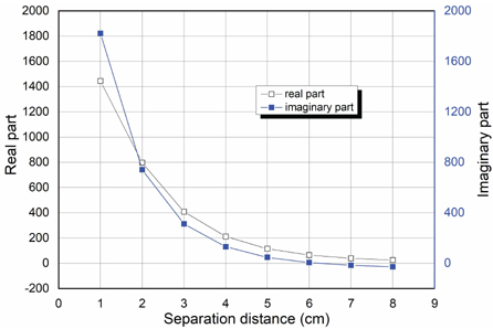
Figure 2: The optimum load impedance versus the separation gap between the Tx and Rx coils.
For the WPT system shown in Fig. 1 (a), the optimum load impedance can be evaluated through (1) and the curves are shown in Fig. 2. It is seen that the optimum load impedance is a complex number. In addition, both the real and imaginary parts of the optimum load impedance tend to decrease with the separation gap. This phenomenon is related to the factor that the coupling coefficient K is reduced for a large separation distance. Before we proceed to simulate this optimum load impedance, it is interesting to investigate the behaviors of the WPT system with such an optimum loadimpedance.
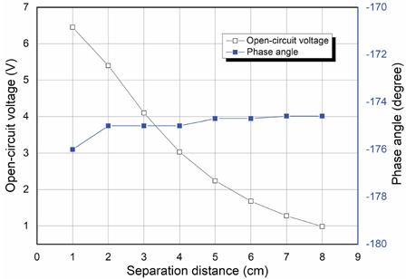
Figure 3: The open-circuit voltage of the Rx coil versus the separation gap between the Tx and Rx coils.
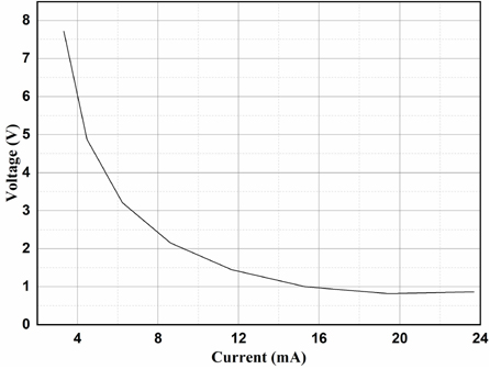
Figure 4: V-I curve of the optimum load.
B. V-I characteristics of the optimum load impedance
Based on the analysis in Part A, the optimum load impedance for the WPT system can be evaluated as shown in Fig. 2. However, the inherent characteristics of the optimum load impedance is not clear. The voltage-current (V-I) characteristic curve is a useful tool for analyzing the load impedance. It this case, we assume that an excitation voltage is applied to the Tx coil, and the open-circuit (OC) voltage of the Rx coil can be obtained for different separation distances as illustrated in Fig. 3. With the OC voltage applied to the optimum load impedance, we can further obtain the V-I curve of the optimum load impedance, as shown in Fig. 4.The V-I curve shows clearly that the optimum load behaves like a voltage-controlled resistor, in which its resistance reduces rapidly if the OC voltage increases.
One may denote such an ideal V-I curve using the curve fitting technology. Based on our investigation, a five-order polynomial expression is sufficient for depicting such a V-I curve, which reads
| (2) |
Equation (3.2) yields a good accuracy for this problem.
Table 1: Curve-fitting coefficients of the V-I curve
| Coefficient | Value | Coefficient | Value |
|---|---|---|---|
IV. REALIZATION OF THE OPTIMUM LOAD IMPEDANCE
The optimum load impedance yields certain nonlinear responses with regard to the OC voltage across the load of the Rx coil. A possible scheme for realizing such optimum load impedance is illustrated in Fig. 5. It consists of a fixed resistor and a variable capacitor. It is noted that capacitance of the variable capacitor should be a function of the applied voltage U as
| (3) |
The current induced by the applied voltage U across the optimum load is then obtained by
| (4) |
We can further expand (4) into three items as
| (5) |
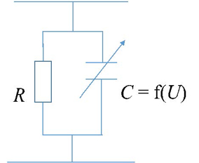
Figure 5: The proposed realization of the optimum load.
Consider a time-harmonic excitation as
| (6) |
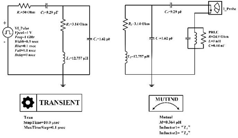
Figure 6: ECM of the WPT system with optimum load.
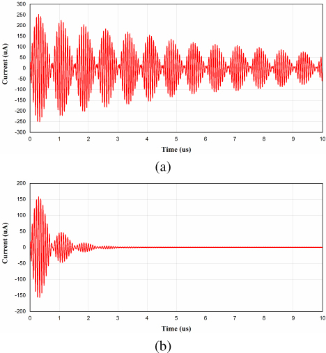
Figure 7: Induced current across the load of the Rx coil (separation distance equals 4 cm, unit pulse is applied): (a) optimum load and (b) 50 load.
By comparing (3.2) and (5), it can be concluded that the unknown function must be a fourth-order polynomial of U to achieve the required fifth-order approximation in (3.2).
For verification of the proposed realization of the optimum load impedance, the MR-WPT system is modeled with an equivalent circuit model (ECM) [10], [11], as shown in Fig. 6. The ECM consists of three parts: the Tx coil, the Rx coil, and the realized load. Transient simulations of the ECM are performed, and the results are shown in Fig. 7. A unit step is added to the feeding point of the Tx coil, and an ordinary 50 load and the optimum load are used to connect the Rx coil, respectively. It is seen that in the beginning the realized load is overvoltaged and then its capacitance starts to change. After a short time, the whole system is stable with a constant output current. This shows that the proposed realization of the optimum load impedance can compensate the WPT system with different separation distances. On the other hand, if a 50 load is adopted to connect the Rx coil, the induced current across the load is much smaller in magnitude. The current is faded into zero in a short time, as the WPT system yield low quality factor with a 50 load.
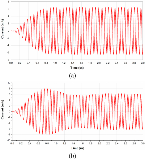
Figure 8: Induced current across the load of the Rx coil (separation distance equals 4 cm, time-harmonic excitation at 13.56 MHz): (a) optimum load and (b) 50 load.
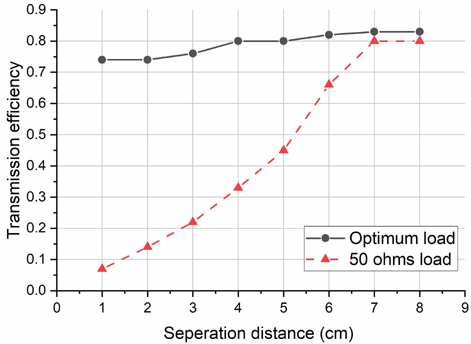
Figure 9: Transmission efficiency of the WPT system with the optimum load and 50 load.
Time-harmonic solution may be also applied to the ECM model in Fig. 6. For the same separation distance (i.e., 4 cm), the induced currents at the Rx at 13.56 MHz are shown in Fig. 8. It is clearly seen that the optimum load reaches stable power transmission in a short time. But the WPT system with 50 load yields some fluctuations in a much longer time, which affects the transmission efficiency at last. Figure 9 compares the transmission efficiency of the same WPT system with the optimum loads and 50 load at 13.56 MHz. The transmission efficiency of the WPT system with 50 load decreases significantly with a reduced separation distance, as the resonant frequency splits as shown in Fig. 1 (b). The usefulness of the optimum loads can be comprehended from those results.
The cost of the whole system would not increase by loading extra impedance. We may use a varactor to realize the optimum loads, which is cost efficient if compared with other methods. This is an advantage of the presented method. Since the selection of a proper varactor is another important topic, the experimental results are not available in this work.
The Rx coil is a passive device and hence one may not consider its sensitivity. The Rx coil would drive a rectifier circuit for extracting power from the WPT system, and the output voltage of the Rx coil is an important factor. The loading varactor would not affect the output voltage of the Rx coil; instead it can keep the whole system stable and more efficient.
V. CONCLUSION
In this paper, a new realization of an optimum load for a WPT system is reported, which can change the loading impedance accordingly for different coupling coefficients between the Tx and Rx coils. A simple varactor circuit is adopted to realize the optimum load curve. Usefulness of this realization is demonstrated through both the steady and transient analyses. The proposed realization relies on an open-circuit scheme, and hence it is suitable for the scenarios with low-cost and small-size requirements.
ACKNOWLEDGMENT
This work is supported in part by the National Natural Science Foundation of China under grant U2141230.
The authors thank Mr. Zhongkui Wen and Yijie Yang for assisting some numerical simulations.
REFERENCES
[1] A. Kurs, A. Karalis, R. Moffatt, J. D. Joannapoulos, P. Fisher, and M. Soljacic, “Wireless power transfer via strongly coupled magnetic resonances,”Science, vol. 317, pp. 83-86, 2007. https://www.science.org/doi/10.1126/science.1143254
[2] Y. Guo, L. Wang, and C. Liao, “A general equivalent model for multi-coil wireless power transfer system analysis and its applications on compensation network design,” Applied ComputationalElectromagnetics Society (ACES) Journal, vol. 33, no. 6, pp. 648-646, June 2018. https://journals.riverpublishers.com/index.php/ACES/article/view/9121
[3] G. Perez-Greco, J. Barreto, A.-S. Kaddour, and S. V. Georgakopoulos, “Effects of the human body on wearable wireless power transfer system,” Applied Computational Electromagnetics Society (ACES) Journal, vol. 35, no. 11, pp. 1454-1456, Nov. 2020. https://journals.riverpublishers.com/index.php/ACES/article/view/7655
[4] D. Kim, A. T. Sutinjo, and A. Abu-Siada, “Near-field analysis and design of inductively-coupled wireless power transfer system in FEKO,” Applied Computational Electromagnetics Society (ACES) Journal, vol. 35, no. 1, pp. 82-93, Jan. 2020. https://journals.riverpublishers.com/index.php/ACES/article/view/8043
[5] D. Schneider, “Wireless power at a distance is still far away [Electrons Unplugged],” IEEE Spectrum, vol. 47, no. 5, pp. 34-39, May 2010. https://ieeexplore.ieee.org/document/5453139
[6] H. Ron, W. Zhong, and C. K. Lee, “A critical review of recent progress in mid-range wireless power transfer,” IEEE Transactions on Power Electronics, vol. 29, no .9, pp. 4500-4511, Sep. 2014. https://ieeexplore.ieee.org/document/6472081/
[7] N. Kyungmin, J. Heedon, M. Hyunggun, and B. Franklin, “Tracking optimal efficiency of magnetic resonance wireless power transfer system for biomedical capsule endoscopy,” IEEE Transactions on Microwave Theory and Techniques, vol. 63, no. 1 pp. 295-304, Jan. 2015. https://ieeexplore.ieee.org/document/6957601/
[8] H. Nguyen and I. A. Johnson, “Splitting frequency diversity in wireless power transmission,” IEEE Transactions on Power Electronics, vol. 30, no. 11, pp. 6088-6096, Nov. 2015. https://ieeexplore.ieee.org/document/7089278/
[9] S. Cheon, Y.-H. Kim, S.-Y. Kang, M. L. Lee, J.-M. Lee, and T. Zyung, “Circuit-model-based analysis of a wireless energy-transfer system via coupled magnetic resonances,” IEEE Trans. Industrial Electron., vol. 58, no. 7, pp. 2906-2914, July 2011. https://ieeexplore.ieee.org/document/5560805/
[10] J. Bito, S. Jeong, and M. M. Tentzeris, “A real-time electrically controlled active matching circuit utilizing genetic algorithms for wireless power transfer to biomedical implants,” IEEE Trans. Microw. Theo. Techniq., vol. 64, no. 2, pp. 365-374, Feb. 2016. https://ieeexplore.ieee.org/document/7384758
[11] Z. Zhang, H. Pang, A. Georgiadis, and C. Cecati, “Wireless power transfer – An overview,” IEEE Trans. Industrial Electron., vol. 66, no. 2, pp. 1044-1058, Feb. 2019.
[12] P. Liang, Q. Wu, H. Bruens, and C. Schuster, “Efficient modeling of multi-coil wireless power transfer systems using combination of full-wave simulation and equivalent circuit modeling,” 2018 IEEE Int. Symp. Electromag. Compat. and 2018 IEEE Asia-Pacific Symp. Electromag. Compat. (EMC/APEMC), Singapore, pp. 466-471, 2018. https://ieeexplore.ieee.org/document/8393822
[13] Z. Wen, Q. Wu, O. F. Yildiz, and C. Schuster, “Design of experiments for analyzing the efficiency of a multi-coil wireless power transfer system using polynomial chaos expansion,” 2019 Joint Int. Symp. Electromag. Compat., Sapporo and Asia-Pacific Int. Symp. Electromag. Compat. (EMC Sapporo/APEMC). https://ieeexplore.ieee.org/document/8893695
[14] J. Zhang, J. Zhao, Y. Zhang, and F. Deng, “A wireless power transfer system with dual switch-controlled capacitors for efficiency optimization,” IEEE Trans. Power Electron., vol. 35, no. 6, pp. 6091-6101, June 2020. https://ieeexplore.ieee.org/document/8892619
[15] F. Grazian, T. B. Soeiro, and P. Bauer, “Inductive power transfer based on variable compensation capacitance to achieve an EV charging profile with constant optimum load,” IEEE Journal Emerging Selected Topics in Power Electron., vol. 11, no. 1, pp. 1230-1244, Feb. 2023. https://ieeexplore.ieee.org/document/9813693
[16] D. Ahn, S. Kim, J. Moon, and I.-K. Cho, “Wireless power transfer with automatic feedback control of load resistance transformation,” IEEE Trans. Power Electron., vol. 31, no. 11, pp. 7876-7886, Nov. 2016. https://ieeexplore.ieee.org/document/7368178
[17] W. Zhong, and S.Y. Hui, “Reconfigurable wireless power transfer systems with high energy efficiency over wide load range,” IEEE Trans. Power Electron., vol. 33, no. 7, pp. 6379-6390, July 2018. https://ieeexplore.ieee.org/document/8024081
[18] D.-G. Seo, S.-H. Ahn, J.-H. Kim, S.-T. Khang, S.-C. Chae, J.-W. Yu, and W.-S. Lee, “Power transfer efficiency for distance-adaptive wireless power system,” Applied Computational Electromagnetics Society (ACES) Journal, vol. 33, no. 10, pp. 1171-1174, Oct. 2018. https://journals.riverpublishers.com/index.php/ACES/article/view/8973
[19] N. Fortana, S. Barmada, M. Raugi, D. Brizi, and A. Monorchio, “Spiral resonator arrays for misalignment compensation in wireless power transfer system,” Applied Computational Electromagnetics Society (ACES) Journal, vol. 37, no. 7, pp. 765-773, July 2022. https://journals.riverpublishers.com/index.php/ACES/article/view/18111
[20] M. Fu, H. Yin, M. Liu, Y. Wang, and C. Ma, “A 6.78 MHz multiple-receiver wireless power transfer system with constant output voltage and optimum efficiency,” IEEE Trans. Power Electron., vol. 33, no. 6, pp. 5330-5340, June 2018. https://ieeexplore.ieee.org/document/7976358/
[21] M. Fu, H. Yin, X. Zhu, and C. Ma, “Analysis and tracking of optimal load in wireless power transfer systems,” IEEE Trans. Power Electron., vol. 30, no. 7, pp. 3952-3963, July 2015. https://ieeexplore.ieee.org/document/6876181
BIOGRAPHIES

Chaoling Wang received the B.E. Degree from Airforce Engineering University in communication engineering. His research interest includes fiber communications and photoelectronic imaging technology. He is currently pursuing the Ph.D. degree at Beihang University, Beijing, China.

Qi Wu received the B.S. degree from East China Normal University, Shanghai, China, and the Ph.D. degree from Shanghai Jiao Tong University, Shanghai, China, both in electrical engineering, in 2004 and 2009, respectively.
He joined the faculty of School of Electronics and Information Engineering, Beihang University, Beijing, China, in 2009 and now is a full professor. During 2011 and 2012, he was a visiting scholar in the Department of Electrical Engineering, University of California, Los Angeles. During 2014 and 2016, he was an Alexander von Humboldt Fellow in the Institute of Electromagnetic Theory, Technical University of Hamburg, Germany. He has authored over 40 journal papers and two books and holds 20 patents as the first inventor. His research interests include broadband antennas, computational electromagnetics, and related EMC topics.
Dr. Wu received the Young Scientist Award from the International Union of Radio Science (URSI) in 2011, the Nominee Award for Excellent Doctoral Dissertation from the National Minister of Education in 2012, Young Scientist Award of APEMC in 2016, and Excellent Researcher from Chinese institute of Electronics in 2020.
ACES JOURNAL, Vol. 38, No. 9, 681–686
doi: 10.13052/2023.ACES.J.380907
© 2023 River Publishers