Enhancing Performance of Distributed Transactions in Microservices via Buffered Serialization
Kindson Munonye* and P. Martinek
Budapest University of Technology and Economics Budapest, Hungary
E-mail: kindson.munonye@edu.bme.hu; martinek@ett.bme.hu
*Corresponding Author
Abstract
Although the Microservices Architecture comes with a number of benefits, it is a challenge to design an efficient transaction management for multi-agent transactions that span across multiple services. Since microservices design require a loose coupling between service logic and resources, data used by a distributed transaction is spread across different nodes, there is need to an effective way to ensure data portability, speed consistency for transaction in microservices. Therefore this research addresses both the issue of improving transaction performance and maintaining data portability for distributed transactions in microservices. A novel approach to transaction management termed ‘buffered serialization’ is proposed in this research as a way to improve transaction management by the use serialization libraries. This work has a three-part objective which are (1) to highlight the challenges of distributed transaction management in microservices, (2) to propose an enhanced approach to transaction management through the use of buffered serialization between services (3) to provide a proof of concept for this novel approach. Obtained result indicate a 60% improvement in transaction failure recovery time, 10% higher success rate for load tests but an insignificantly higher resource utilization values.
Keywords: Distributed Transactions, Microservices, Transaction Management, Serialization, Protocol Buffer, Buffered Serialization, Appointment transaction processing
1 Introduction
Before highlighting the key concepts of transactions in the context of microservices, it is necessary to provide an overview of microservices and why an efficient transaction management is a present challenge in microservices design. As has been identified in many texts, microservices provides a framework for building enterprise applications as a suite of services which are independently deployable, implementable in different programing paradigms and platforms and can be managed by different development teams [1, 2]. Compared to the monolithic design pattern, microservices provides a more flexible and scalable application with each service centered around a single business function [3]. The microservice architectural pattern partitions and information systems into a set of microservices [4, 5] that would have to exchange data at some point in the application life-cyple. In this way the application logic cosists in operations that access distributed data from two or more services. Since each microservice will have its own resourcees, the effect of changes made to resources across microservices has to be made consistent
Dataflow across services require a constant serialization between data formats since services making up and MSA are not guaranteed to be homogeneous. The well-known Transaction Control Protocol/Internet Protocol(TCP/IP) has been the de-factor technique for data exchange and therefore, inter-services communication have mainly been achived through the HTTP (Hypertext Transfer Protocol), messaging and events where data is exchange either in plain text, XML or JSON formats. However, the TCP does not provide the reliability and consistency required for most enterprise application which requires granularity in the way data is send and received [5]. Additionally, as the number of services in a distributed transaction increases, a chain of sub-transaction is formed such that failure has to be managed efficiently to maintain data consistency and application stability [6]. In the context of this research, a transaction, as would be discussed in details in subsequent sections. In this research, a distribued transaction is modeled as a change or exchange of values between two or more services.
Other issues arising due to non-homogeinity of services includes complexity, inter-communication between services, data sharing and others which are outlined in [7]. However, this research addresses the issue of portabiliity via buffered serialization, consistence via efficient failure recovery and consistencey across services participating in a distributed transaction. Specifically, a novel approach introduced by this research would provide a multi-faceted solutions to the three challenges outline.
The examples used throughout this research would be based on a subset of a Medical Informations Sytem(MIS). Analysis would focus on the transaction processing steps of a patients appointment reservation with a physician via distributed transaction processing ecosystem. Also note that the terms Hosptal Information System(HIS) and Medical Information System(MIS) are used interchangeably through this text.
The rest of this paper is arranged as follows: Chapter 2 provides an overview of current approaches to transaction management in distributed systems including microservices. In chapter 3, the theoritical model of the buffered serialization approach proposed in this research is covered. In chapter 4, the methods and proof of concept used to realized our novel enhanced approach are presented. The benefits of our model over existing models are also presented in chapter 4. Then in chapter 5, the results of the evaluation of our model in an operational test environment is presented. Finally, in Section 6, the conclusion and possibilities for future research are reported.
2 Review of Transactions in Microservices
In this section, we provide a literature review of existing approaches to distributed transaction management. We also outline the current challenges faced with these approaches.
2.1 Sagas
Traditionally, the management of distributed transactions predates the advent of microservices architecture. In 1987, Keneth Salem published a paper on distributed transactions which he termed Long-Lived Transactions(LLT) or saga [8]. This is defined as a transaction that can be split into a collection of sub-transactions which can be interleaved in any way with other transactions. This has since formed a basis for managing transactions in distributed environments including microservices architecture. Related to the Saga is transaction log-tailing. This employs the database transaction log to ensure that each transaction is published automatically as an event [9]. Figure 1 shows a basic saga case study where a distributed transaction consists of 3 pairs of local transactions. In this case a transaction would depend on the completion of the subsequent sub-transaction in the saga. This means the a hotel must be reserved and confirmed before car is booked. Similarly, a car is booked before a flight is booked and so on. So if the hotel reservation succeeds but the car booking fails, then the previously succeeded transaction has to be undone.
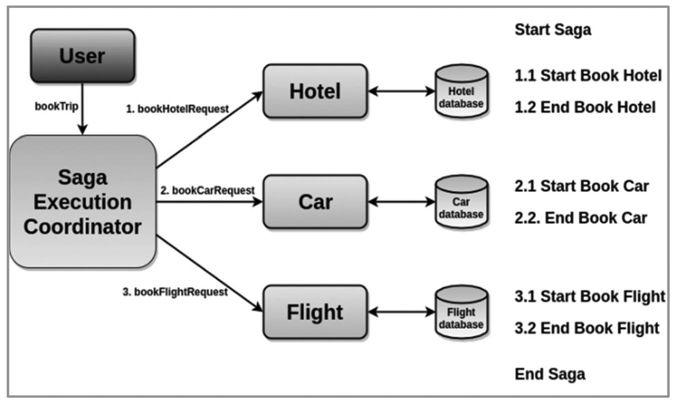
Figure 1 A basic Saga case study adapted from [10].
Two basic types of Saga are (1) Choreograph Saga (2) Orchestration saga.
2.2 Choreography-Based Saga
For transaction processing using the choreography-based saga, each microservice executes a local transaction and then ‘informs’ the next microservice to proceed with the next logical action[11]. This communication is done by events which are published by a microservice to indicate that an operation has been performed. This is illustrated in Figure 2 using a typical appointment booking workflow for Hospital Information System (HIS) for booking appointment with a physician. When the appointment is successfully created, an AppointmentCreated event is published by the Appointments Service and this event is subscribed to by the Billing service. The cycle of event publishing and subscription continue till the last local transaction in the chain.
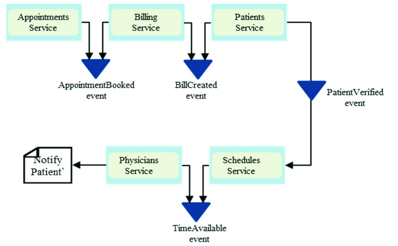
Figure 2 Choreography-based Transaction.
The choreography-based approach comes with the requirement that if any of the local transactions fails, then there would be a way to rollback all the previous successful transactions in the saga. This is achieved by providing a compensating transaction for each successful transaction. A compensating transaction is executed by a service to roll back a successful transaction to maintain consistency. However, two challenges arises: (1). it becomes very complex handling a situation where one or more compensating transactions fails. (2) providing additional transactions for every local transaction adds to the overhead of the microservices architecture and increases the complexity.
2.3 Orchestration-Based Saga
The second approach to transaction management is called Orchestration. This is illustrated in Figure 3. In this method, there a central component called the orchestrator which coordinates the transactions.
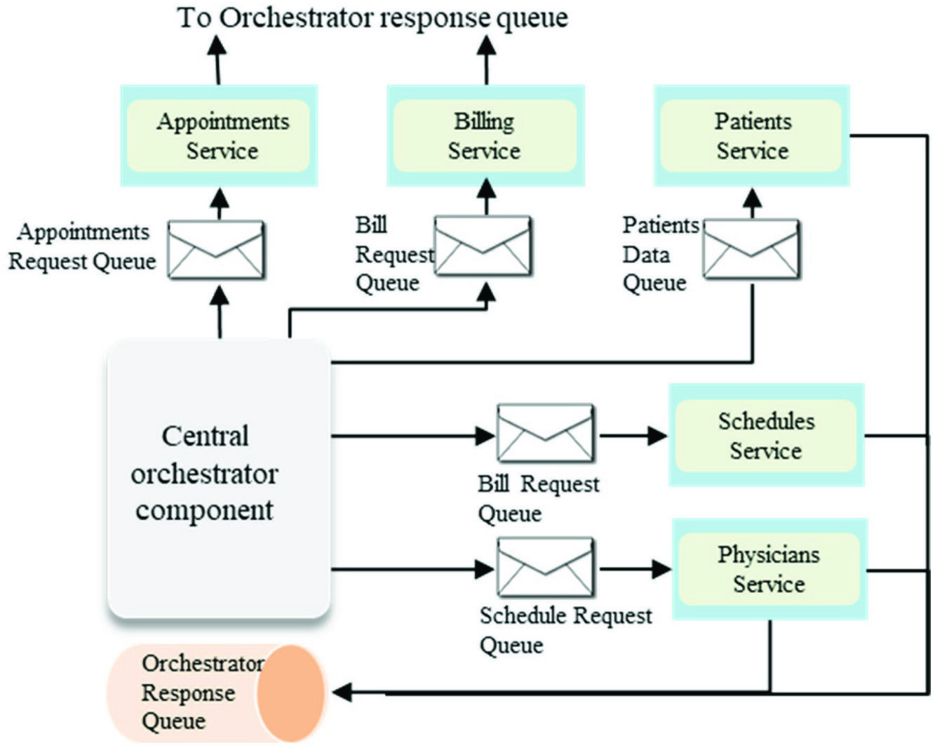
Figure 3 Orchestration-based transaction.
Unlike the choreography which publishes events to the next service, events in an orchestration are published to the central orchestrator which can then route it to the appropriate service. The challenge with the orchestration pattern is that it provides a single point of failure for the architecture. Therefore, a failure in the orchestrator would result in all the services being unavailable. Moreover, complexity increases by adding an additional component that requires a tight coupling with every other service.
2.4 2-Phase and 3-Phase Commit
Another approach to distributed transactions is the 2-Phase Commit(2PC) and 3-Phase Commit (3PC) which tries to achieve consistency by applying a distributed algorithm to databases systems for transaction that require simultaneous data update[12]. As indicated in Figure 4, the two-phase commit protocol consists of two components: the coordinator which acts as a master node, and then all other nodes called the participants. The transaction model includes two phases. In the first phase(Voting), the participants indicates readiness to commit. If all the participants are ready, then the second phase(Completion) is executed. However, if any of the participants is not ready to commit, then then an Abort is executed in the second phase.
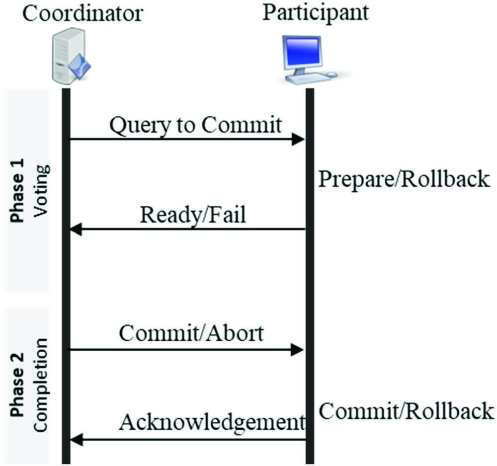
Figure 4 2-Phase commit architecture.
This algorithm provides for state transitions in the course of transactions such that current local transaction could obtain a lock on resources. This places other transactions in blocking state, therefore, violating the Availability requirement which is necessary for both ACID(Atomicity, Consistency, Isolation and Durability) and BASE(Basic Availability, Soft- State, Eventual-Consistency) transactions [13].
The 3PC attempts to address the problem of blocking by providing an intermediate phase between the first and second phase. This state allows for a waiting time for all the participants to vote ‘yes’ (ready to commit) and all the resources are available. In this case, after a pre-specified timeout period, an Abort operation is executed and all the held resources are released. In some cases however, the 3PC exhibits the same flaws of the 2PC.
2.5 The SagaMAS
A different approach termed the SagaMAS [14], described as a multi-agent based framework for distributed transactions for microservices. The SagaMAS proposes an additional layer of abstraction called the agent layer which trades consistency for eventual consistency and as such relaxes the ACID requirements for databases to BASE(Basic Availability, Soft-state and Eventual Consistency). This approach proposes a third layer of functionality, the agent layer which brokers transactions between services. However, this approach is aligned with the orchestration approach discussed earlier and have not yet been complete as of the time of this research.
2.6 Compensating Transactions
Compensating transaction are transaction executed to semantically undo the effect of a successful transaction [15]. In the book Practical Microservices Architectural Patterns, the concept of distributed saga is discussed [5]. Here a transaction is consisting of two parts: transaction (T) and compensating transaction(Ci). Although this forms the bases of the choreography and orchestration-based sagas, in this context, a transaction is considered as an HTTP request or event. A compensating transaction is provided to semantically undo a previously completed transaction. Therefore, a distributed saga provides a guarantee that either of T, T, …, T or T, T, …, T, C, …, C, C is successfully completed. Therefore, a consistent state is always maintained. Then a log, called the saga log is used to persist the state of every transaction/operation that occurs in the course of a given transaction. This use of distributed saga include addition of the certain components including Saga Execution Coordinator(SEC), Saga log, Control Bus and Message Sequence. All these not only adds to the complexity but still has the same shortcoming of Choreography and Orchestration based transactions. Moreover, this is based on the assumption that a compensating transaction will always be successful.
2.7 Deterministic Database Technologies
The approach as proposed in [16] recommends the use of existing database technologies and optimistic concurrency protocol (OCC). Here, a transaction is executed optimistically with its read-set while the write set is captured during the execution phase. Then at commit time, a decision is made by first persisting the committed transaction in a log and then asynchronously applying the changes to a database. However, microservices implementations does not always guarantee use of dbs that support OCC.
2.8 Buffered Serialization Approach
This is a novel approach proposed in this research that combines the benefits of both the choreography and orchestration patterns but introduces an additional component, the buffered serializer. This additional component ensures that transaction metadata across microservices are serialized and deserialized using a common structured format. Additionally, the serializer component would ensure that transaction data is available for recovery of a failed transaction. The buffered serialization approach unlike existing approaches, allows for a retry of a transaction in case of failure. The term was coined in the course of this research to indicate two attributes of the transaction metadata: (1) it is cached on the service side, and (2) handles serialization of data. The idea is simply a way to cache each local transaction metadata in a platform-agnostic format such that when there is a failure, the metadata could be used to re-attempt the transaction and restore the system to a consistent state. The methodology is discussed in details in the chapter 3 and 4.
3 Buffered Serialization General Model
In this section, a general overview and theoretical model for the realization of the buffered serialization approach to transaction management is provided.
3.1 Overview of the Buffered Serialization
Buffered serialization basically aims to improve data exchange performance between services via a centralized serialization. Serialization is the process applied in translating data structures or object state into a format that can be persisted or transmitted and then reconstructed later [17]. Therefore the objective of the buffered serialization are twofold namely:
1. Provide an intermediate representation of the service objects easily serializable by the services
2. Provides a medium(buffer) to hold metadata of currently executing transactions
The concept of buffered serialization which involves three basic heuristics (1) the transaction throughput depends on the rate of marshaling and unmarshaling on structured data between services (2) a platform-agnostic middleware between the services (3) improved transaction performance is achieved if inter-services communication is done asynchronously [18].
Figure 5 shows a basic serialization model as proposed in this research. A serialization component is used as a middle-tier between services. This allows the serialization-deserialization overhead to be delegated away from the microservices which could now focus on the transaction logic. Therefore, transactions between services are routed through the buffer component which contains transaction metadata shared across services. The buffer component in Figure 5 contains classes and objects shared between services during transaction.

Figure 5 Basic serialization model.
A failure in a distributed transaction that involves services 1, 2 and 3 would be recovered in a timely manner using metadata available in the buffer component as shown in Figure 1.
3.2 Microservice Transaction Data Interchange
The key application of buffered serialization in microservices is data interchange in the context of inter-service interaction. Conventionally, HTTP currently provides the mechanisms for network communication. For instance, request initiation, authentication and message routing between transactions are all based on HTTP. However, network protocols basically do not regulate the content and structure of the transaction data [19]: they simply allow transfer of any media type which then have to be serialized and deserialized by each service. So if for examples, if there a transaction spans m services with each service having n local transactions, then then total number of serialization/deserialization(ser/des) steps would be . With buffered serialization, the number can be reduced to since ser/des across services now takes place at an abstract buffer layer. The buffer layer (part of the central orchestrator) is provided on top of the network protocol and defines and unified representation of the data structure. This is illustrated in Figure 6. Protocol buffers for example provides a cross platform method for serializing arbitrary data structures into well defined messages that can be exchanged using any protocol. The descriptors (.proto files in case of Google Protocol Buffer serializer) are used to formally declare the interface of a remote API or network application. Libraries are available to parse and generate protobuf messages for a wide range of programming languages. This makes it relatively easy to implement in a microservices architecture.
Figure 6 indicates data exchange scenario for the use case analyzed in this research. Communication with external services are done via HTTP (fat arrows) while communication with internal services happen via the buffered serialization interface (broken lines).
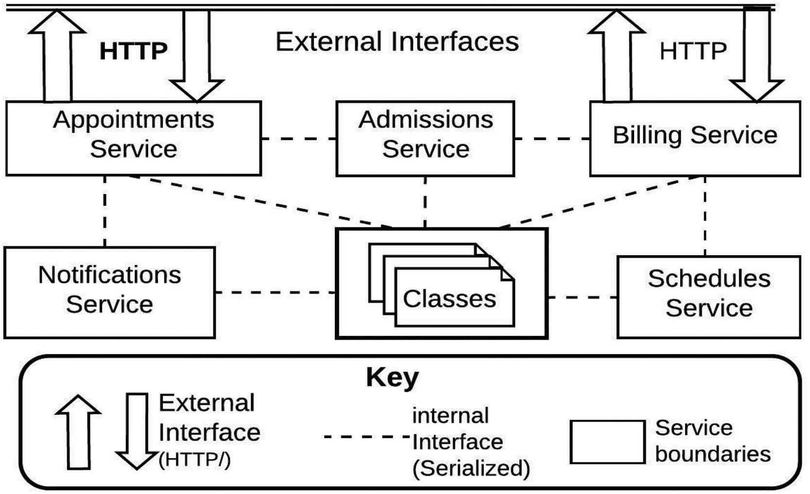
Figure 6 Buffered serialization use case.
3.3 Existing Serialization Components
As part of selecting a serialization framework for microservices, a number of existing solutions were evaluated as presented in this section.
BinaryFormatter serializer is provided for the .Net framework as an all-inclusive binary serializer and performs well for Remote Procedure Call (RPC) senerios. Other similar .Net based serializers includes DataContractSerializer and JSON.NET [17]. Apache Avro designed by Apache Software Foundation also performs binary serialization and is platform agnostic [17, 20]. Then, there is Protocol buffer developed by Google. This also performs binary serialization and uses assigned tag to serialize and deserialize structured and unstructured data formats [21, 22]. Actual implementation of serialization as well as additional tools and techniques a covered in chapter 4.
3.4 Transaction Flow Algorithm with Protocol Buffer
We now present a general algorithm for the transaction flow through the buffered serialization microservices architecture and shown in Figure 7.
Let’s assume a distributed transaction T. which consists of two local transactions L an L corresponding to microservices MS and MS
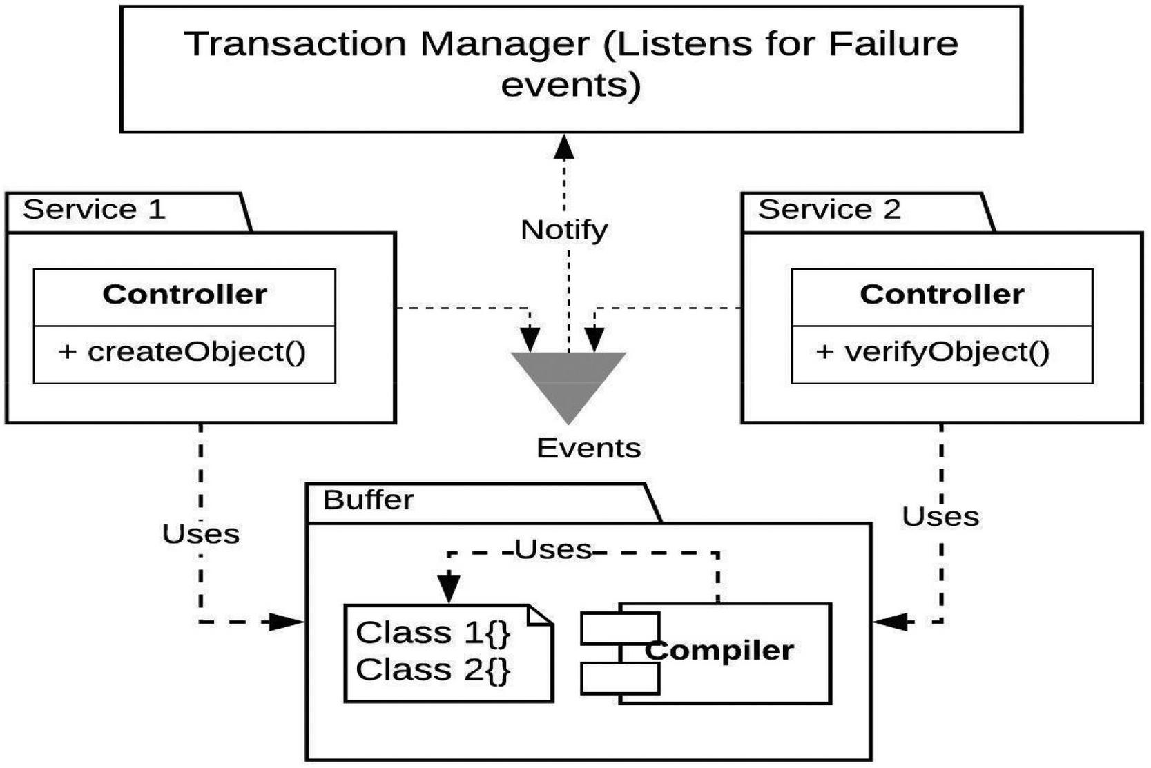
Figure 7 Interservice Communication for buffered serialization.
A restore() function is implemented in the transaction manager component.
The restore() function takes three parameters namely:
MS, S, S
In a normal transaction, when MS1 executes a local transaction, L1 and the state of a collection in MS1 changes from S0 to S1
A success messages is registered with the agent layer for MS0 MS1, assuming MS0 represents a successful initialization of the distributed transaction.
Then the next local transaction L2 is executed. If it runs successfully, then a success event is sent to the agent layer for MS1 MS2. However if there is a failure in MS2, the local transaction L2 execute a logic that rolls back the operation and a failure event is raised to the agent layer for MS1 MS2. At this point, the agent calls the restore function using the parameters MS1, S10, S11.
The restore function has the following signature
Function restore(MS1, S10, S11)
Temp = S0
S10 = S11
S11 = temp
RaiseSuccessEvent()
So basically, the restore function reverts the state of the service to the original state without any loss of metadata. This provides the option of execution of the restore() function a number of times in case of failure in the restore operation.
3.5 The Transaction Model
A detailed transaction model for the buffered serialization approach is presented and this section which is based on the principle of state machine. The following lemmas are applied based on Figure 8.
Lemma 1: A distributed transaction is represented by a tuple T = L, L, …, L) where n 1 and L,…L are local transactions.
Lemma 2: For each distributed transaction T comprising lf local transactions L, L,… L, there exists serialized metadata C, C, …, C corresponding each of the local transactions.

Figure 8 The CTD Architecture.
Lemma 3: For every T, there exists a path from L to L which may contain cycles.
Lemma 4: The serialized metadata in C, C,…C is updated for every new transaction and remains active for the lifetime of the transaction.
Lemma 5: There is 1/n possibility of failure for the transactions where n is the number of transactions and the transactions execute in saga. Therefore transaction L completes execution(succeeds or fails) before transaction Land so on. Let failure in a transaction L be represented with Fi.
With the above 5 lemmas we now define a formal transaction model using the following algorithm
• A transaction is initiated in MS(A by an external event
• MS executes the transaction L and updates the serialized metadata C
• A success event is published to the Central Orchestrator
3.6 Failure and Recovery Model
Based on the architecture on Figure 8, we now simulated a failure in MS which is the last service in the system. MS attempts to execute local transaction L which fails with an internal rollback logic. At this point, the central orchestrator is notified about the failed transaction in MS where i = 5. The agent layer calls the restore function on MSi-1 where is now 4. The restore function executes on MS4 and notifies the agent layer which triggers another restore function in MS3. The restore process continues down the layers of transaction until the start transaction is reached.
Using the appointment transaction processing case study as shown in Figure 8 (covered in chapter 4), we can now outline the algorithm(with a simulated failure) as follows:
1. New appointment requests are pushed to the Appointment Service (MS1) from an integrated client interface. This executes local transaction L1
2. A serialized metadata of the appointment object is created in MS1
3. System creates a new appointment object with a status attribute of “Pending” and inserts the object into the persisted data store(DB1) at timestamp T2
4. User enters personal details in a UI where validation tasks are processed (T3)
5. When the ‘Pending’ appointment is found, the VerfiyUser process is invoked. User details is retrieved if the user is recognized. Otherwise, a new Patient object is created and returned. New record is inserted into the PostgreSQL table (T4)
6. User provides a specialty for the appointment and other details(T5)
7. Cost of appointment based on user specification is retrieved and relayed to the client service (T6)
8. A bill object is created (T7) with a status attribute of “Not Paid”. At this point, the Billing Service creates a JMS message out of the information contained in the bill data and is sent to an ActiveMQ queue for BillProcessing. (T8)
9. The bill is (expected to be) paid and at this point the payment is confirmed and the status attribute of the Bill is set to “Paid”(T9)
10. Availability of a physician is confirmed based on specialty and physician is notified (T10)
11. Then a schedule needs to be verified for availability of a time slot for the appointment (T11). At this point, the schedule verification fails
12. The central orchestrator is notified of the failure through an event. Then using the serialized metadata, the central orchestrator initiates a recovery process.
From the 12-step algorithm presented, based on Figure 8, it can see that if buffered-serialization approach not only conforms to the principle of loose-coupling but also ensures data consistency is maintained. The basic database pattern applied in Figure 8 is the Database-Per-Service(DBPS), therefore the approach proposed in this research combines the DBPS pattern with the serialization pattern and ensures that transaction efficiency and data consistency can be maintained irrespective of the database platform implemented for each service.
3.7 Performance Evaluation
The transaction model as well as the failure and recovery model indicates a stateful system with the data excahge across the states are based on a common data format. Therefore, this model can be extended to more complex distributed transaction. The next consideration evaluation of the TTR(Time-To-Recover) or recovery time. The analysis provides a way to record the timestamp at each local transaction and used for performance evaluation. This evaluation is covered in chapter 4.
4 Methodology, Design and Implementation
This section follows from the previous chapter an provides a proof of concept of the buffered approach to transaction management.
4.1 Methodology
The general models outlined in chapter 3 has to be formalized in order to properly implement a functional microservices transaction framework. To achieve this, the buffered serialization approach follows the Prometheus methodology [23]. A software methodology for developing multi-agent systems. The Prometheus methodology defines a detailed process for specification, design, implementation, testing and debugging software systems [24]. It also specifies an array of artefacts that are created in each state of the design process. The methodology in the context of transactions involves three phases as shown in Figure 9:
• System Specification
• Architectural Design
• Detailed Design
These three phases progress iteratively aligning with the Rational Unified Process(RUP) scheme [25].
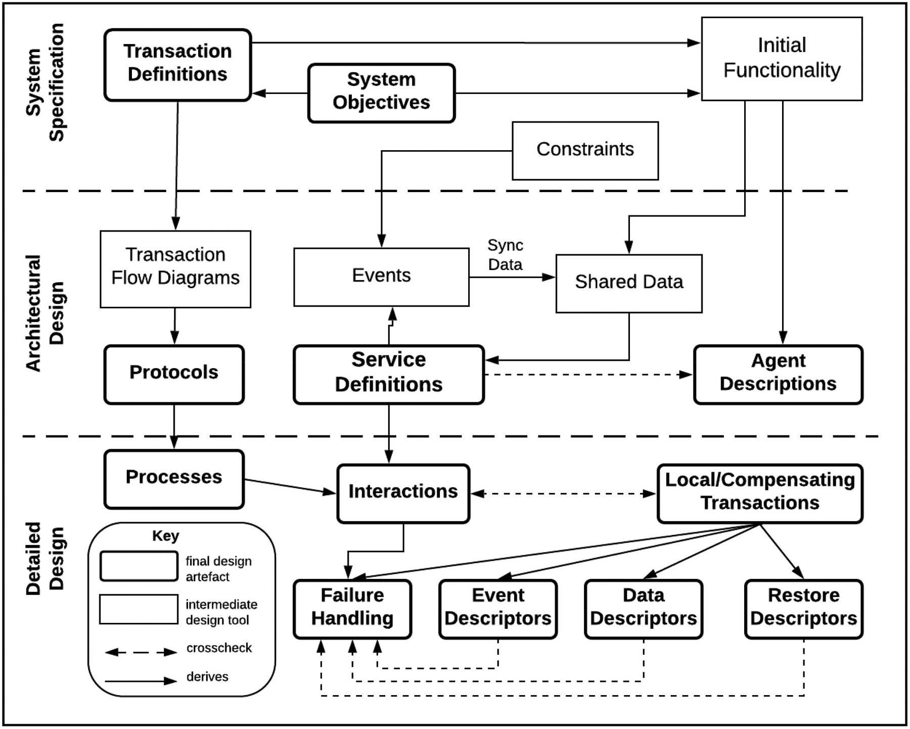
Figure 9 Phases of the Prometheus Methodology adapted from [14].
In the next three subsections, the three phases of the methodology for buffered serialization is presented. However, the focus is on analysis of single transaction flow within the system
4.2 System Specification
This phase involved specifying the goals that relate with the system requirements. It also requires specification of functionalities related to the identified goals. There is also a speciation on how the system interface with external environment in which it is situated. In the case of a distributed transaction, the entrypoint and termination rules for the transaction is specified. The use case is a Medical Information System(MIS) which serves as a case-study for this research is a complex system consisting of various internal and external interfaces. It can well be modeled as a microservices architecture. For this 7 service are identified, namely:
• EMR(UI Service) – This is the entry-point to the system. Since the focus on transaction management, the UI service interfaces with the Appointment service.
• Appointments Service: This service on the basic, manages creation and confirmation of appointments
• Schedules Service: This service manages the schedules of pending and confirmed appointments. Also hold information on Physician’s daily calendar
• Billing Service: This service is responsible for creating of new Bill as well as updating existing bill
• Admissions Service: Handles data entry and management of patient data
• Notifications Service: This service handles routing of notification between agents
• Buffered Serialization Component: This is the main component that interfaces with other services. Class definitions for common classes are centralized here. Moreover, it is used a temporary buffer for lived transaction metadata
System goals include error handling, connectivity information, transaction processing and failure recovery
4.3 Architectural Design
The architectural design indicates the system component and their interaction. To reduce complexity, only the features of the system concerned with appointment processing has been indicated in Figure 10. This represent interactions between services. The key aspect is that the various microservices maintain a centralized store of common classes. This make is very fast for the serializer component to perform marshalling and unmarshalling across classes. The serialization component consists of a compiler and a definition of the common classed. The output of this component is collection classes targeted accessible to all subscribing services.

Figure 10 System Architectural Design.
4.4 Transaction Flow Design
A basic design of the transaction process as presented in Figure 11 details the transaction steps involved in an appointment reservation process. Again, a basic design provided(rather than a detailed design). This is to reduce the complexity related with a diagrammatic representation of a system as complex as an enterprise MIS. So subset is used with all the components that serves as endpoints for transaction processing. Figure 11 provides the detailed design of the transaction processing which correspond to the architectural design of Figure 11.
It is important to note that the distributed transaction is normally initiated from an external interface. In the use case of appointment processing, the external interface is the EMR(UI) service. Communication between the external interface is handled by a default HTTP/JSON communication without a buffered serialization. However, once the transaction is initiated with the first local transaction being executed, then the common classes are set up in the buffer component as well as the transaction metadata. From this point, further communication is channelled through buffered serializer interface in the in a service-independent format. Similar external interface as shown in Figure 11 is the External Payment Process which communicates with the MSA similar to the communication between the EMR(UI) and the Service 1 (Appointment Service)
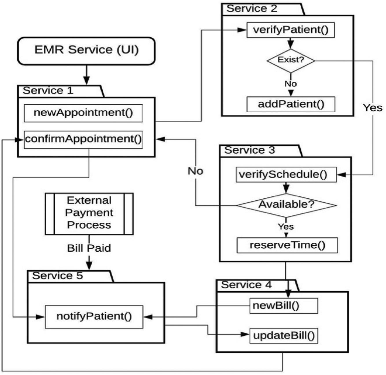
Figure 11 Transaction flow design.
4.5 Buffered Serialization Libraries
A key consideration for buffered serialization application in distributed transaction is an efficient serialization technique that improves the overall performance of the system. The following options, though still being research on, were considered:
• Protocol Buffer: This is developed by Google and used by them as an internal hybrid language data standard [19, 26]. It is a lightweight efficient exchange data storage format used for structured data serialization. It is also platform independent.
• JSON Message Format: JSON which means JavaScript Object Notation.
• Thrift: This is a software library and asset of code-generation tools originally developed by Facebook [27]. It is similar to Protobuf but supports programming languages like C++, Java, Python and PHP.
• Avro: Apache Avro is a serialization framework developed as a Hadoop subproject and provides serialization formats for persistent data and communication between Hadoop nodes [27]. It uses JSON for schema definitions.
• MessagePack: This is a computer data interchange format that used binary representation for simple data structures [28]. It supports a number of languages including Python, Java, C++, JavaScript, C# and Swift.
• Other serialization libraries include XML, Smile, FlatBuffers, BSON, ProtoStuff and CBOR [29]. Table 1 lists the libraries evaluated during this research as research on application of others are ongoing.
Table 1 Data Serializers Evaluated
| Serializer | Based on | Standardized | Binary | Readable |
| ProtoBuf | Text | No | yes | Partial |
| Thrift | NA | Yes | No | Yes |
| Avro | JSON | No | Yes | No |
| FlatBuffers | NA | No | Yes | Yes |
| MessagPack | JSON | No | Yes | No |
| Smile | JSON | Yes | No | Yes |
| CBOR | JSON | YES | Yes | No |
4.6 System Implementation
Coordination of transactions across multiple services was achieved using the X/Open Architecture(XA) standard which is supported by Java and integrated into Spring Framework. Java Transaction API (JTA) and Java Transaction Service(JTS) are the two interfaces provide by XA. The application architecture for the prototype was created using Spring Framework with Eureka based on Spring cloud. Hence the microservices were registered as Eureka clients. Data persistence for each of the service was implemented using PostgreSQL for the Appointment Service and Patients Service, MySQL for the Physician Service, then Apache Derby for the Notification and Schedule Services.
Messaging is provided by Java Messaging Service(JMS) which provide message routing feature between services [30]. ActiveMQ was used which was integrated into Spring Framework using the ActiveMQ dependencies.
The logic for communication with the Agent Layer was implemented as part of the Saga Execution Coordinator (SEC). The SEC orchestrates the entire transaction logic and is responsible for the successful execution of the transaction. It is able to read and write to the session variables for each service as well as the transaction log. However, this research focuses on the role of the SEC as an agent that listens to failure events and returns the system to a consistent state in case of a failure event emitted by one of the microservices.
4.7 Performance Evaluation
We now need to provide a framework for evaluating the performance the architecture. The objective is to measure the transition time between two consistent states. The metrics of interest include: transaction time (T), restore time (R), transaction success rate and resource utilization. The basic evaluation setup is given in Figure 12. The initial time t is evaluated at the beginning of the transaction. Then for subsequence microservices, the current timestamp is recorded. For this research failure is simulated at MSn and therefore recovery time R is recorded sequentially for each service in the recovery part until he MS0. Then both transaction time and recovery time are evaluated for each failure location.

Figure 12 Basic evaluation setup for simulated failure.
Hence the initial consistent state occurs just at the start of the transaction L1. Let’s call this time t1. Then the system move through series of soft states until the next consistent state t2. State t2 is attained when the transaction terminates with successful completion of all the local transactions or a restore of all transactions preceding a failure.
This is illustrated in Table 2 which shows the time profile for the physician appointment booking microservice. In this example, we simulate a failure at the last transaction L8 (verifySchedule) which occurs at t9.
Table 2 Transaction Timestamp Profile
| Start | T1 | LTX* | Restore | |
| bookAppointment | T2 | L1 | R() | T17 |
| inputPatient | T3 | L2 | R() | T16 |
| verifyPatient | T4 | L3 | R() | T15 |
| retrieveCost | T5 | L4 | – | – |
| createBill | T6 | L5 | R() | T14 |
| confirmPayment | T7 | L6 | R() | T13 |
| verifyPhyician | T8 | L7 | R() | T12 |
| verifySchedule | T9 | L8 | R() | T11 |
| confirmAppointment | T10 | L10 | T() | T10 |
| LTX – Local Transactions. | ||||
From Table 2 we could see that the we would could isolate the worst-case scenario as the failure of the local transaction L1) which would require 7 unique restore operations. It is also important to note that some local transactions, L4 for example does not require a restore operation. However, the execution time of this transaction impacts on the overall restore times for any failure in all subsequent transactions (L5 to L10 in this example)
In the next chapter, we carry out a series of evaluations simulating failure and success scenarios.
5 Results and Discussion
In this section we present the results of several test cases executed against buffer serialization-based transactions. The objective is to examine the performance of the approach using various techniques and compare them with conventional approach of basic HTTP calls. Specifically, we perform two test setups:
1. Transaction Processing Time
2. Recovery Time Analysis
3. Performance on Load
4. Resource Utilization
The transaction processing time analysis aims to determine transaction processing time required to complete a distributed transaction(T1 - T10). Recovery time analysis is aimed to discover total time(T1 - T1) it takes the system to attain a consistent state after a failure occurs in one of the local transactions (L1 – L10). Then the Resource Utilization examines the consumption of system resources with focus on memory consumption and CPU.
5.1 Test Configuration
Since the buffered approach addresses the issue of maintaining system consistency after a failure, the results presented in this section includes a simulation of failure at each service and evaluation of the complete recovery time. Table 3 indicates a transaction profile used, with of t and therefore, timestamp at subsequent transactions are recorded. Column RM indicated the request method for a current local transaction while column restore indicates the corresponding for a compensating transaction.
Table 3 Appointment processing transaction time profile
| Start (t0) | RM* | TX | Restore | t1 |
| newAppointment | POST | L1 | PUT | T1 |
| VerifyPatient | GET | L2 | NA | T2 |
| addPatient | POST | L3 | PUT | T3 |
| VerifySchedule | GET | L4 | NA | T4 |
| reserveTime | PUT | L5 | PUT | T5 |
| newBill | POST | L6 | PUT | T6 |
| notifyPatient | POST | L7 | POST | T7 |
| updateBill | PUT | L8 | PUT | T8 |
| updateSchedule | PUT | L9 | PUT | T9 |
| confirmAppointment | PUT | L10 | NA | T10 |
| RM – Request Method | ||||
| t – Transaction Initiation Timestamp | ||||
| t – Restore Timestamp | ||||
| Recovery Time t = t - t | ||||
A four-step restore process is indicated in Figure 13 from the first step which is the initiation of the transaction to the fourth step which is the restore task. Hence the five recovery steps based on the Appointment processing transaction are as follows:
Step 1: external initiates a transaction in the appointment service
Step 2: Local transaction in Appointments updates the values of the serialization metadata
Step 3: Appointment service attempts to execute the newAppointment task to writes data to the database which fails
Step 4: Appointments service emits a failure events
Step 5: Event is registered to the listener but since this is the first service in the transaction, no restore operation is performed.
The restore column of Table 3 indicates the HTTP method for the recovery operation. This is similar but not same as compensating transaction implemented in Sagas.
5.2 Local Transaction Processing Time
The results below in this section provides an insight into the transaction processing time(seconds) for each serialization method implementation. 2500ms was injected to account for delay for external input as explained in Chapter 4. It can be observed from Table 4 that the use of Protocol Buffer(PB) provides a best transaction processing time (112s-2918s). Compared with the conventional approach with a processing time range of 388-3192s, this represents a 52.83% improvement in local transaction processing time. It necessary to note that the None column indicates time measurements for test cases where not buffered serialization is used.
Table 4 Transaction processing time comparison
| T | None | PB | Thrift | Avro | FBuffers |
| T1 | 388 | 112 | 289 | 245 | 219 |
| T2 | 606 | 324 | 395 | 268 | 230 |
| T3 | 862 | 420 | 573 | 311 | 832 |
| T4 | 1382 | 600 | 587 | 419 | 881 |
| T5 | 2121 | 819 | 895 | 519 | 956 |
| T6 | 2479 | 1218 | 976 | 730 | 1156 |
| T7 | 2915 | 1947 | 1089 | 785 | 1475 |
| T8 | 3010 | 2149 | 2344 | 1281 | 1995 |
| T9 | 3113 | 2601 | 2403 | 2232 | 2014 |
| T10 | 3192 | 2418 | 2820 | 2429 | 2920 |
Figure 12 shows a comparison between the average transaction processing time for buffered serialization method and non-buffered-serialization method. It can clearly be seen that provides a lower transaction time(max. of 2800ms) against default (max of 3200ms). Average was taken for the four serialization libraries with lowest transaction time.
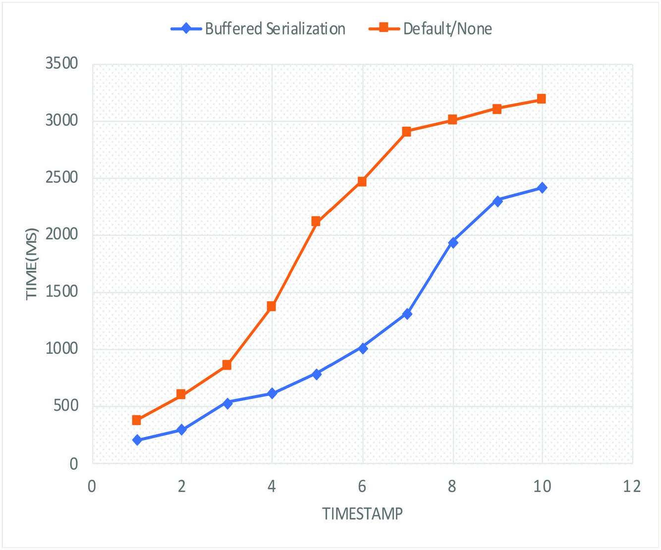
Figure 13 Transaction processing time comparison.
5.3 Failure Recovery Time Analysis
The goal of this analysis is to evaluate the time (in milliseconds) taken to restore the system to a consistent state after a failure. This is referred to as correlation time in an earlier research [31] comparing performance of choreography vs orchestration-base microservices. We choose the term recovery time to relate more to the concept of recovery after a failure. In the test case shown in Figure 12, a failure in the Appointments service (MS) is simulated at the failure point (marked x) for local transaction L6. Since a failure of MSi would trigger a restore for MSi-1. Since i = 1 and MS would be 0 and MS does not exist in the current scenario, therefore we only have :
Restore time = Recovery Time
This is the same as the time taken to a HTTP status response of 404(message not available) in case of a HTTP request from L to L.
In the next test case, a failure is simulated in MS, which results in a restore operation for MS. Then a failure simulated in MS would require a restore operation for MS and MS and so on. Therefore we define the depth recovery tree as “the number of services in the path of the transaction from the initial transaction to the failed transaction”. Hence, in Figure 12, the depth of the re is 5. This is indicated by column d* in Table 5. Figure 12 further highlights the sequence of restore function R() executed in case of a failure. A failure in local transaction L triggers restore operations for L – L.
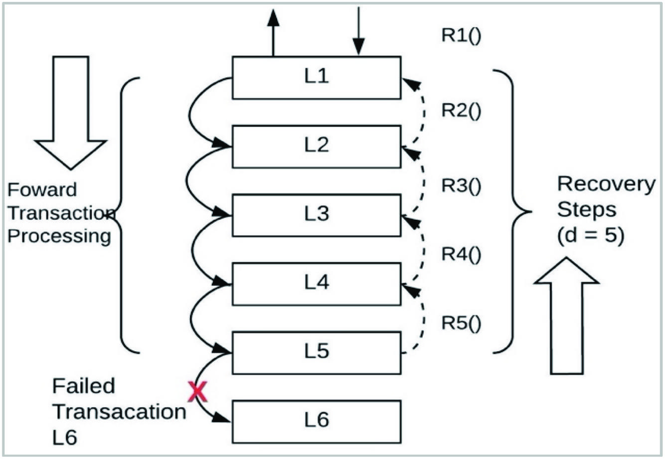
Figure 14 Recovery steps for d = 4.
In Table 5, we present an evaluation provide of restore times relative to the depth of the distributed transaction tree up to the point of failure. For each test suite, the average recovery time is computed and recorded. T refers to the time it takes to restore the current service.
Table 5 Restore times for profile templates
| -Services | d* | TX | t0-t1(ms) | |
| MS1 | 0 | L1 | DEL | T1 |
| MS2 | 1 | L2 | DEL | T2 |
| MS3 | 2 | L3 | DEL | T3 |
| MS4 | 3 | L4 | - | T4 |
| MS5 | 4 | L5 | DEL | T5 |
| MS6 | 5 | L6 | PUT | T6 |
| MS7 | 6 | L7 | PUT | T7 |
| MS8 | 7 | L8 | PUT | T8 |
| MS9 | 8 | L9 | PUT | T9 |
Table 6 indicates the recovery time recorded for each depth where T2 represents the recovery time for depth of 1 and so on. It is observed an increasing recovery time as depth of the DDT increases. This is consistent with the findings in [31] which also provides a proof of direct proportional relationship between the correlation time and number of services. Only the first 5 with highest recovery time is indicated. PB and indicates the best recovery time (6011–6018s) which is at least 60% improvement of the buffered serialization over conventional method (not in Table 6).
Table 6 Transaction restore times comparison
| T | PB | Thrift | Avro | FB | MP |
| T2 | 83 | 616 | 371 | 1827 | 219 |
| T3 | 473 | 1668 | 426 | 2225 | 602 |
| T4 | 883 | 1839 | 777 | 2232 | 1223 |
| T5 | 1493 | 2682 | 1680 | 4114 | 1420 |
| T6 | 3351 | 4448 | 2159 | 4367 | 1523 |
| T7 | 3726 | 4471 | 2331 | 4559 | 3786 |
| T8 | 4724 | 4592 | 2701 | 5620 | 4753 |
| T9 | 5639 | 4769 | 3761 | 5623 | 4822 |
| T10 | 6183 | 6011 | 6764 | 6194 | 6477 |
Summary of Table 6 is provided in Figure 14 as a comparison into of restore times for buffered serialization approach relative to conventional methods. It could be seen that use of buffered serialization provided better performance with a max time of 5500ms against the default of 6500ms. The curve of Figure 14 considered the 4 best performing buffered serialization method.
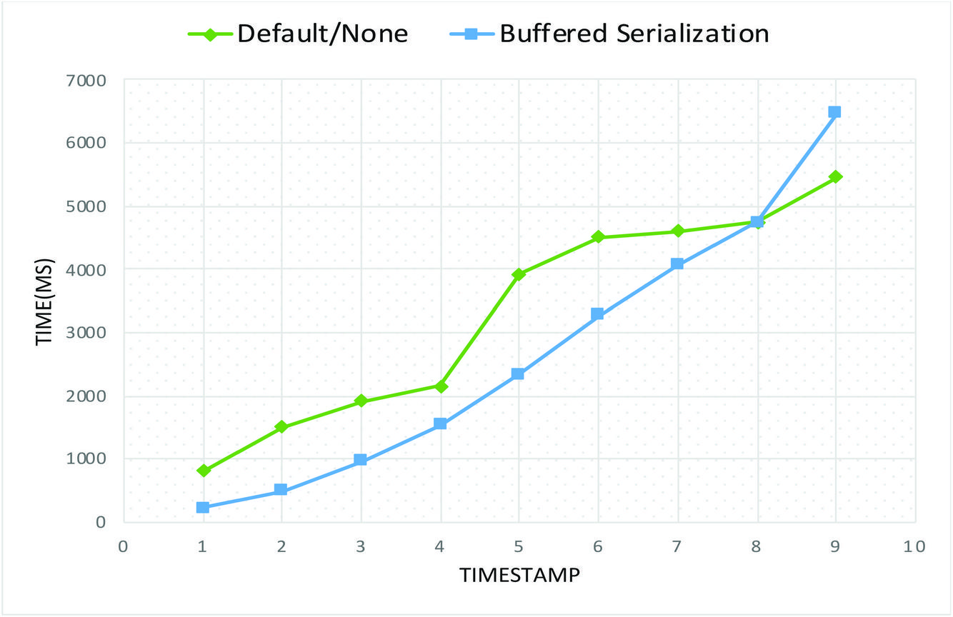
Figure 15 Recovery time comparison.
5.4 Total Transaction Performance Test Results
The objective of these tests is to determine the performance of the transaction models under various normal conditions. Table 7 shows a test scenario of 1000 request with 10 threads. The best processing delay time was recorded for Thrift(31 secs) while the least total time was recorded for PB(6:65). Similarly, total number of completed request of 4943 was recorded for PB. I could also be observed from Table 7 that 3450 requests was completed for None(Default) which is well below average number of completed threads. None refers a default serialization method provide the framework. For example Spring Framework provides JacksonSerializer which used JSON, XML and Plain Text over HTTP.
Table 7 Performance Test – Scenario 1(1000 requests, 10 Threads)
| Serializer | Processing Delay | Total Time | Completed Requests |
| None | 00:43 | 06:45 | 3450 |
| ProtoBuf | 00:50 | 01:20 | 4671 |
| Thrift | 00:31 | 07:22 | 4943 |
| Avro | 00:41 | 05:41 | 4660 |
| FlatBuffers | 00:33 | 05:12 | 4966 |
| MessagPack | 00:50 | 06:38 | 4832 |
| Smile | 00:55 | 05:34 | 3163 |
| CBOR | 00:36 | 08:35 | 4945 |
Table 7 indicates a test scenario with an increased request from Table 7 (10,000 request and 100 threads). The best processing delay time was recorded for Thrift(31 secs) while the least total time was recorded for PB(8:27). Similarly, total number of completed request of 4943 was recorded for PB.
Table 8 Performance Test – Scenario 2(10,000 requests, 100 Threads)
| Serializer | Processing Delay | Total Time | Completed Requests |
| None | 01:33 | 07:45 | 13,971 |
| ProtoBuf | 00:32 | 08:27 | 14,443 |
| Thrift | 01:26 | 07:34 | 12,269 |
| Avro | 01:56 | 08:32 | 11,905 |
| FlatBuffers | 01:27 | 06:13 | 12,262 |
| MessagPack | 00:30 | 09:48 | 10,157 |
| Smile | 01:36 | 07:55 | 11,049 |
| CBOR | 00:14 | 07:50 | 14,284 |
5.5 Load Test Results (50,000 requests/100 threads)
The objective of these tests are to examine the application behaviour for multi-threaded clients can be multi-threaded and repeated load. As shown in Table 8, 50,000 request of 100 thread test suite was used. Although this is an aspect of performance testing [32], the focus is on rate of success for each test case. Table 9 indicates the Thrift performed best with a 72,731 completed request of 72.3%. The key point to not is that implementation without the buffered serialization approach produced a success rate of 62% which is less 10% less than results obtained using serialization.
Table 9 Load test – scenario 3 (50,000 requests, 100 threads)
| Serializer | Processing delay | Total Time | Completed Requests | SR |
| None | 03:42 | 32:56 | 62000 | 62.00% |
| ProtoBuf | 01:36 | 35:48 | 60673 | 60.67% |
| Thrift | 02:34 | 43:16 | 72731 | 72.73% |
| Avro | 04:22 | 35:41 | 70765 | 70.77% |
| FlatBuffers | 02:1 | 46:55 | 62987 | 62.99% |
| MessagPack | 03:19 | 31:3 | 57535 | 57.54% |
| Smile | 00:10 | 28:8 | 56744 | 56.74% |
| CBOR | 00:51 | 35:53 | 56557 | 56.56% |
I could also be seen from Table 9 that the success range of SR 56.56% - 72.73% is acceptable only for experimental purposes since a single instance of each service was deployed.
5.6 Resource Utilization Evaluation
Table 10 presents a result of resource utilization test carried out with the goal of checking for possible performance degradation in case of long-lived transactions. The same setup was used for different scenarios. First, a database write failure was introduced for the newAppoinment event with a payload of 5 fields, each with a fixed width of 250 characters. The process was repeated with a 2-fold increase in the payload and then 4, 6…up to 10.
Figure 15 shows the results of two all cases. As can be seen, the memory utilization (red curve) remained within a fixed range throughout the live of the transaction failure and recovery.
Table 10 CPU resource utilization
| Serializer | Min | Max | Average |
| None | 19 | 28 | 23.5 |
| ProtoBuf | 11 | 21 | 16 |
| Thrift | 23 | 41 | 32 |
| Avro | 18 | 24 | 21 |
| FlatBuffers | 27 | 48 | 37.5 |
| MessagPack | 28 | 45 | 36.5 |
| Smile | 17 | 29 | 23 |
| CBOR | 15 | 20 | 17.5 |
The focus is on the impact on memory consumption and the results indicates a significantly constant memory usage for each successive test case(single distributed transaction. This indicates that use of cached data while it improve consistency, does not impact on system resource. It can be observed from table 5.9 that for test case executed with basic serialization (None) the memory utilization ranged from 14 to 26 units. However, the use of Protobuf indicates a slightly lower memory utilization of 9 to 17 which confirms that effect on memory could be considered insignificant.
Table 11 Memory utilization summary
| Serializer | Min | Max | Average |
| None | 14 | 26 | 20 |
| ProtoBuf | 9 | 17 | 13 |
| Thrift | 11 | 34 | 22.5 |
| Avro | 23 | 34 | 28.5 |
| FlatBuffers | 13 | 17 | 15 |
| MessagPack | 16 | 42 | 29 |
| Smile | 10 | 35 | 22.5 |
| CBOR | 22 | 15 | 18.5 |
Figure 15 shows the CPU utilization performance in % of CPU during the transaction. The key aspect is evaluation of the best resource utilization time for used of buffered serialization against conventional method(None). It can be observed that Protocol Buffer (dark red curve) at the lowermost point performs the best with a range of between 0 and 10% CPU utilization. This is an improvement over the Default(None) which provides a higher CPU utilization of between 20% and 25%. The Avro serializer provides the highest CPU utilization of approx. 30% to 35%. It is important to not that the results are intended to be comparative based on constant values of the network environment and system specifications.
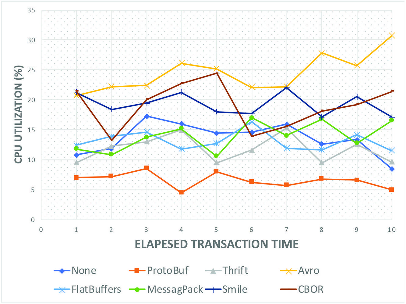
Figure 16 CPU Utilization all Serializers.
Figure 15 shows the CPU utilization performance in % of memory during the transaction. It can be observed that Protocol Buffer was observed to provide the best memory utilization range of 0 to 14%. However, the FlatBuffers provided the most stables utilization range with a fluctuation of only 5%. The default serialization method(None) could be seen as the second place from Figure 16 while serializers such as Avro and Thrift provided a worst-case scenario of between 25%–35% and between 15% to 25% respectively.
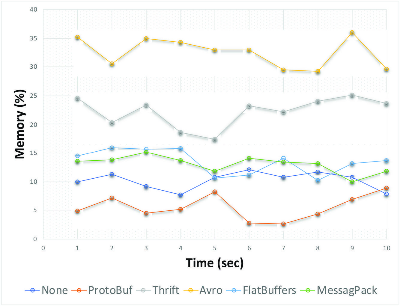
Figure 17 Memory Utilization all Serializers.
From the various experiments performed, it could be observed that the used of the buffered serialization approach have varying performance depending on which serialization libraries were used.
On the average the use of buffered serializers performs better than conventional methods with the Protocol Buffer giving the best performance. These results could possibly be different if multiple instances of same transaction was executed rather than a single instance and adopting a load-balancing technique. Research on this is currently on-going.
6 Summary and Conclusion
The approach to transaction management proposed in this research, buffered serialization promotes a flexible and efficient way of handling transaction and maintaining data consistency in cases of a failed local transaction. The used of a serialized metadata allows for definition of a framework for monitoring an ongoing distributed transaction for the duration of the transaction.
6.1 Summary of Achievements
A new approach to distributed transaction management in microservices that improves performance. The use of buffered serializers between services promotes a complete loose coupling between the services. This is because the handling of transaction integrity and failures is delegated to another component or layer of abstraction.
Evaluation of performance of serialization methods. In this research, a comprehensive experimental evaluation was carried out to verify achievability of this approach. Several successful test cases were executed using both conventional RDBMS which provides a proof of concept for the buffered serialization approach.
This research provides a method or improving data consistency while maintaining the isolation principle of microservices by providing a structured platform-independent component for keeping transaction metadata.
6.2 Challenges Encountered
On aspect that required some attention is the use of simulated network environment for the evaluation and experiments. Although this is accounted for by keeping the network and system parameters constant across the test suites, there’s possibility of different outcome in a production environment. Unfortunately, we could net secure access to a production test environment during this research. However, ongoing efforts are in place.
Non-optimal success-rate for higher transaction loads. Implementation of this approach also shows additional memory requirement for serialized transaction data is insignificant as it simply require less than 2 percent of the standard storage requirement. Besides, since the data is cached, the storage spaced is released at the end of the transaction.
6.3 Possibilities of Further Research
One key area of further research is the application of this approach in cloud, mobile and IoT environment. Currently, experiments are being carried out on the performance of the buffered serialization approach on mobile transactions. This approach provides a number of additional possibilities. For example, a logging of potentially failure-prone transaction could be easily implemented in another layer of abstraction. Or it could be that instead of executing a restore function, in case of failure, a trade-off could be made between availability and consistency to re-execute a failed operation after a predetermined timeout. This would the immediate future work following this one to see the performance impact of these scenarios on the microservice transaction management.
Finally, we are very sure that with further refinement of our methodology, design and implementation framework, the buffered serialization approach would become a de-facto approach to transaction management for microservices.
References
[1] T. Yarygina and A. H. Bagge, “Overcoming Security Challenges in Microservice Architectures,” Proc. - 12th IEEE Int. Symp. Serv. Syst. Eng. SOSE 2018 9th Int. Work. Jt. Cloud Comput. JCC 2018, pp. 11–20, 2018, doi: 10.1109/SOSE.2018.00011.
[2] P. Zaytsev, S. J. Hasaneini, and A. Ruina, “Preprint Pr ep t,” vol. 146, pp. 215–232, 2015, doi: 10.1016/j.jss.2018.09.082.The.
[3] B. Christudas, Practical Microservices Architectural Patterns. 2019.
[4] M. Kalske, N. Makitalo, and T. Mikkonen, “Challenges When Moving from Monolith to Microservice Architecture,” Irene Garrigós Man. Wimmer Curr. Trends Web Eng., vol. 1, pp. 156–165, 2018, doi: 10.1007/978-3-319-74433-9.
[5] B. Christudas, Practical Microservices Architectural Patterns. 2019.
[6] T. Salah, M. J. Zemerly, C. Y. Yeun, M. Al-Qutayri, and Y. Al-Hammadi, “The evolution of distributed systems towards microservices architecture,” 2016 11th Int. Conf. Internet Technol. Secur. Trans. ICITST 2016, pp. 318–325, 2017, doi: 10.1109/ICITST.2016.7856721.
[7] P. Jamshidi, C. Pahl, N. C. Mendonca, J. Lewis, and S. Tilkov, “Microservices: The journey so far and challenges ahead,” IEEE Softw., vol. 35, no. 3, pp. 24–35, 2018, doi: 10.1109/MS.2018.2141039.
[8] H. Garcia-Molina and K. Salem, “Sagas,” ACM SIGMOD Rec., vol. 16, no. 3, pp. 249–259, 1987, doi: 10.1145/38714.38742.
[9] E. Balsamo, “Designing a Microservice-oriented application running on a Serverless architecture,” 2018.
[10] J. H. Li et al., “Research on Architecting Microservices: Trends, Focus, and Potential for Industrial Adoption,” ICPE 2016 - Proc. 7th ACM/SPEC Int. Conf. Perform. Eng., vol. 3, no. 5, pp. 443–452, 2016, doi: 10.1109/ES.2016.14.
[11] M. Stefanko, O. Chaloupka, and B. Rossi, “The saga pattern in a reactive microservices environment,” ICSOFT 2019 - Proc. 14th Int. Conf. Softw. Technol., pp. 483–490, 2019, doi: 10.5220/0007918704830490.
[12] M. Atif, “Analysis and verification of Two-Phase Commit & Three-Phase Commit protocols,” 2009 Int. Conf. Emerg. Technol. ICET 2009, pp. 326–331, 2009, doi: 10.1109/ICET.2009.5353152.
[13] K. Machado, R. Kank, J. Sonawane, and S. Maitra, “A Comparative Study of ACID and BASE in Database Transaction Processing,” vol. 8, no. 5, 2017, [Online]. Available: http://www.ijser.org.
[14] X. Limon, A. Guerra-Hernandez, A. J. Sanchez-Garcia, and J. C. Perez Arriaga, “SagaMAS: A software framework for distributed transactions in the microservice architecture,” Proc. - 2018 6th Int. Conf. Softw. Eng. Res. Innov. CONISOFT 2018, pp. 50–58, 2019, doi: 10.1109/CONISOFT.2018.8645853.
[15] M. Butler, T. Hoare, and C. Ferreira, “A Trace Semantics for Long-Running Transactions,” Springer, Berlin, Heidelberg, 2005, pp. 133–150.
[16] G. Zhang, K. Ren, J. S. Ahn, and S. Ben-Romdhane, “GRIT: Consistent distributed transactions across polyglot microservices with multiple databases,” Proc. - Int. Conf. Data Eng., vol. 2019-April, pp. 2024–2027, 2019, doi: 10.1109/ICDE.2019.00230.
[17] A. Nagy and B. Kovari, “Analyzing . NET serialization components,” pp. 425–430, 2016.
[18] D. Jaramillo, D. V. Nguyen, and R. Smart, “Leveraging microservices architecture by using Docker technology,” Conf. Proc. - IEEE SOUTHEASTCON, vol. 2016-July, pp. 0–4, 2016, doi: 10.1109/SECON.2016.7506647.
[19] D. Eddelbuettel, M. Stokely, and J. Ooms, “RProtoBuf: Efficient cross-language data serialization in R,” J. Stat. Softw., vol. 71, no. Cline, 2016, doi: 10.18637/jss.v071.i02.
[20] B. Carpenter, G. Fox, S. H. Ko, and S. Lim, “Object serialization for marshaling data in a Java interface to MPI,” Concurr. Pract. Exp., vol. 12, no. 7, pp. 539–553, 2000, doi: 10.1002/1096-9128(200005)12:7539::AID-CPE4983.0.CO;2-H.
[21] B. Petersen, Bo Søborg; Bindner, Henrik W.; You, Shi; Poulsen, “Smart Grid Serialization Comparison,” Comput. Conf. 2017, no. July, pp. 1339–1346, 2017, doi: 10.1109/SAI.2017.8252264.
[22] A. Sumaray and S. K. Makki, “A comparison of data serialization formats for optimal efficiency on a mobile platform,” Proc. 6th Int. Conf. Ubiquitous Inf. Manag. Commun. ICUIMC’12, no. 0851912, 2012, doi: 10.1145/2184751.2184810.
[23] L. Padgham, “The Prometheus Methodology Michael Winikoff 433-682 Intelligent Software Agents 2 nd April 2004,” no. June 2014, 2004, doi: 10.1007/1-4020-8058-1.
[24] L. Padgham and M. Winikoff, “Prometheus: A methodology for developing intelligent agents,” Lect. Notes Comput. Sci. (including Subser. Lect. Notes Artif. Intell. Lect. Notes Bioinformatics), vol. 2585, pp. 174–185, 2003, doi: 10.1007/3-540-36540-0_14.
[25] A. Anwar, “A Review of RUP (Rational Unified Process),” Int. J. Softw. Eng., vol. 5, no. 2, pp. 8–24, 2014, [Online]. Available: http://www.cscjournals.org/library/manuscriptinfo.php?mc=IJSE-142.
[26] J. Feng and J. Li, “Google protocol buffers research and application in online game,” 2013 IEEE Conf. Anthol. Anthol. 2013, 2013, doi: 10.1109/ANTHOLOGY.2013.6784954.
[27] K. Maeda, “Performance evaluation of object serialization libraries in XML, JSON and binary formats,” 2012 2nd Int. Conf. Digit. Inf. Commun. Technol. its Appl. DICTAP 2012, pp. 177–182, 2012, doi: 10.1109/DICTAP.2012.6215346.
[28] D. Persson and N. Carlsson, Performance Comparison of Messaging Protocols and Serialization Formats for Digital Twins in IoV. 2020.
[29] “Comparison of data-serialization formats - Wikipedia.” https://en.wikipedia.org/wiki/Comparison\_of\_data-serialization\_formats (accessed Jun. 18, 2020).
[30] R. Henjes, M. Menth, and S. Gehrsitz, “Throughput performance of java messaging services using FioranoMQ,” 2006 13th GI/ITG Conf. Meas. Model. Eval. Comput. Commun. Syst. MMB 2006, no. January, 2006.
[31] C. K. Rudrabhatla, “Comparison of event choreography and orchestration techniques in Microservice Architecture,” Int. J. Adv. Comput. Sci. Appl., vol. 9, no. 8, pp. 18–22, 2018, doi: 10.14569/ijacsa.2018.090804.
[32] S. Kundu, “Web Testing: Tool, Challenges and Methods,” Int. J. Comput. Sci. Issues, vol. 9, no. 2, pp. 481–486, 2012.
Biographies

Kindson Munonye received his M.Sc in Information and Telecommunication Engineering from the University of Port Harcourt, Nigeria in 2016. Previously he obtained a bachelor’s degree in Computer Engineering from the Rivers State University of Science and Technology, Port Harcourt and a Post-Graduate Diploma in Computer Science from University of Port Harcourt, Nigeria. He is currently completing his Ph.D in Software Engineering with the Budapest University of Technology and Economics. He has also attained 9 year work experience in the industry. His research areas includes: Enterprise Application Integration, Microservices, CQRS and Event-Sourcing pattern. Other research interest includes microservices data mining and big data analytics. He has authored/co-authored 7 publications published in international journals.

P. Martinek received his B.Sc, M.Sc. and PhD. degrees in Computer Engineering from Budapest University of Technology and Economics, Hungary. Dr. Martinek is an associate professor at the Department of Electronics Technology at BME since 2012. He is the recipient of the 2010 IBM Faculty award. His main research area is Enterprise Application Integration (EAI), but he also studies production scheduling and optimization of manufacturing processes by machine learning methods.
Journal of Reliability and Statistical Studies, Vol. 19_5-6, 647–684.
doi: 10.13052/jwe1540-9589.19564
© 2020 River Publishers